Input Devices
Group Assignment
In this week assignment we had to measure the power consumption of an input device.
The Oscilloscope in the FabLab was broken this week, so we skipped the task and made our own research in the internet. Here I found this tutorial about how to use an Oscilloscope:
Individual Assignment
The individual task of this week was to design a PCB with an ATmega328P microcontroller. The board then should to be connected to different sensors, as for example a DHT22 Sensor for measuring humidity and temperature.
In the tutorial we were testing a smaller version of the sensor, the DHT11, and we had some problems with the programing of the microchip.
We could figuer out that the reason this was the limited memory capacatiy of the ATtiny44. There is not enough memory to store all the programming and libraries.
It might be a possible, but only when the programming code is in C and the libraries are reduced to a minimum size. But regarding the fact, that I also wanted to add other sensors, I finally chose the ATmega328P and searched for existing versions of a Fabduino, aka Fabkit Board. Here are three examples I found in Fabacademy archive:
I copied from all three examples the part I liked most and started to re-design the PCB. I changed little thing, as e.g. by leaving out the reset button. So for this PCB I used to at least these components:
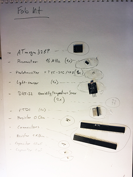
Bill Of Materials (BOM):
- 1x ATmega328P (data sheet ATmega48A/PA/88A/PA/168A/PA/328/P)
- 1x Resonator 20MHz
- 1x Phototransistor PT15-21C/TR8
- 1x FTDI HEADER SMD
- 1x LED (LEDFAB1206)
- 1x Resistor 1KOhm
- 2x Resistor 0Ohm
- 2x Capacitor 1uF
- 4x Connectors 8 Longpads
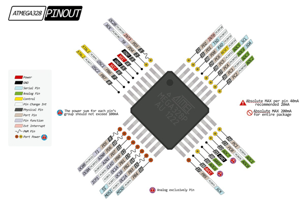
I reviewed the data sheet and then checked the pinouts of the microchip. In the web research I found different versions of pinout plans, from which I chose two examples:
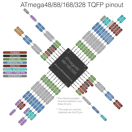
The second diagram also shows the pinout's numbers according to an Arduino Board, which would be the reference for my Fabduino Board:
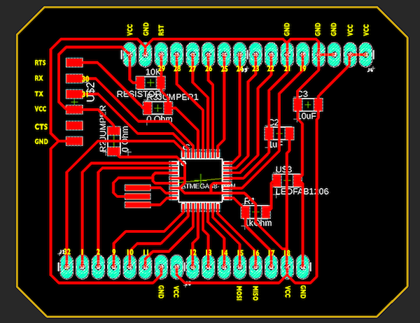
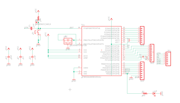
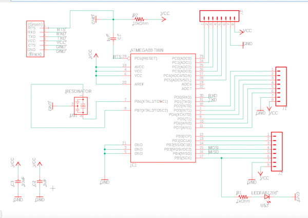
Board Design
To continue with the PCB design, I used the program Eagle:
Design Rules Control
The first board design of the FabKit failed:
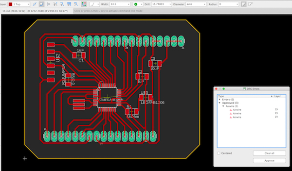
By checking this board design with the instructors, we found out, that the traces were too thin, even though I did the DRC (desin rules control) with this Fab template fabmodule.dru.
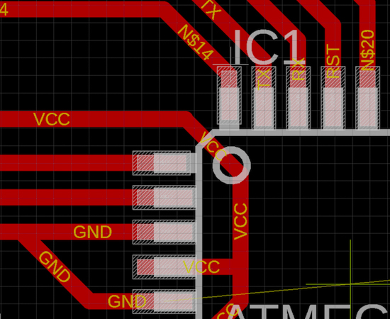
So I had to change the width of the traces from 10 to 14. Actually Actually they should have been 16, but then, in some parts, the traces were too narrow to each other, as shown in this example:
I found a tool in Eagel, with which I could change all traces at once. To get there I followed these steps:
Select only "Top" layer -> activate them all with "Group" tool -> open "ULP" tool and select as you can see in the screen shot above -> "add all" in signal list -> enter "new" wire width.
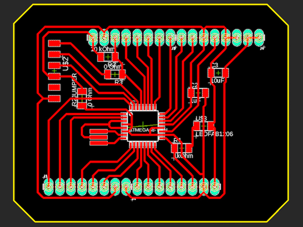
And finally the board design was finished:
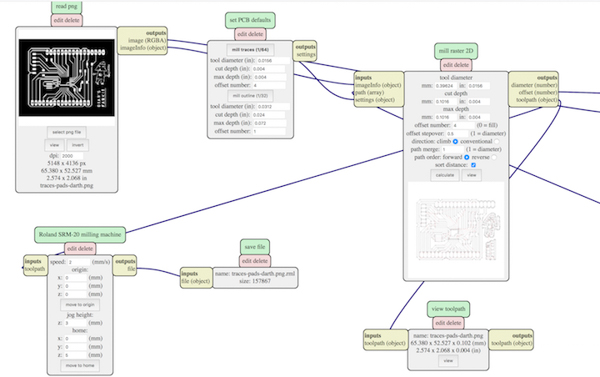
I exported three documents for the traces, holes and frame. And in this order I had to mill well, because the holes should be milled before the frame cut, which otherwise might provoce an unexpected movement of the board's position.
I drawed the traces in white on black background, but the second mill job, with the holes, had to be inverse, so black with on white background.
Milling and Soldering
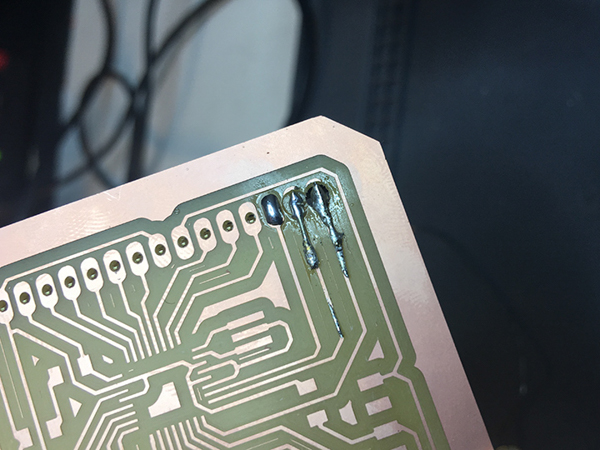
I had stop the first milling job right at the beginning, because the dimensions of the holes were too big.
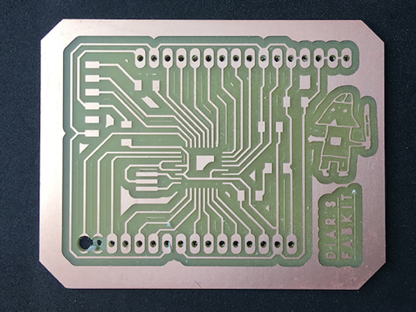
So I went back to invert the image of the holes, as discribed above and ran the job again. Then I recovered the board by soldering little wires on top of the failed holes.
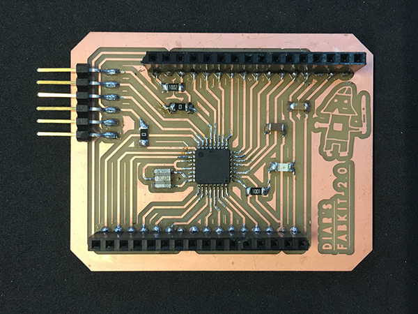
The FabKit was almost finished:
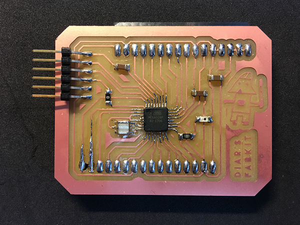
As a variation I soldered the Longpads Connectors to the bottom side, and bended them to the sides.
Programming
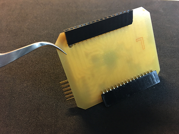
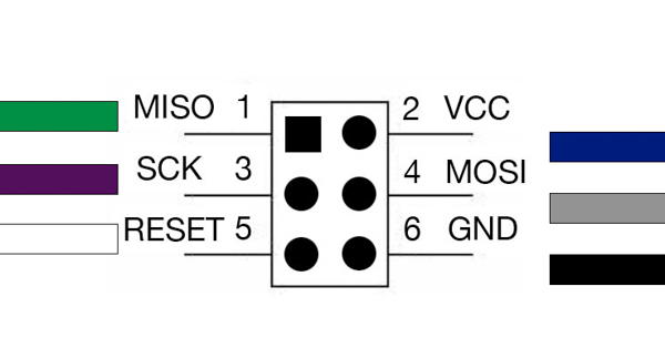
To program the FabKit I used my Fab ISP. I had to make sure that the wires are well connected and checked the pin out of both PCBs.
Then I opened Arduino made the set up with these following steps:
I tested the board, but it failed. I found out that the problem came from the capacitor. Actually capacitors serve to decouple circuits one from an other for the purpose to avoid noise, that could come from other circuit elements. But in my case the capacitor that I put here, was not correct. The capacitor was actually made for button circuit. But as I wanted to leave the button out, I finally had to replace capacitor with an resistor of 0 Ohm, serving as a "jumper".
And last but not least, my FabKitDA 2.0 was finished: