4.1. Group assingment
Team members: Josep Marti, Gustavo Abreu, Diar Amin, Felipe Santos and Alberto Martinez.
4.1.1. Group Laser cutting
For this group assignment we were asked to characterize the lasercutter machines in the FabLab Barcelona to test the cutting and dimension settings for different materials.
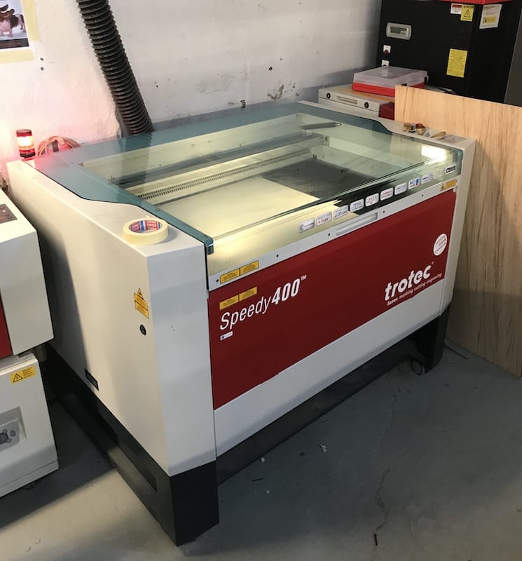
We chose the Trotec Speeedy400 machine from the Lab to do the testings. It has 100W power and a cutting area of 100x60cm.
Material testing
The process of laser cutting starts with a 2D design of the model. This model it will be uploaded to the Lab's Cloud to be processed by any computer and machine in the room.
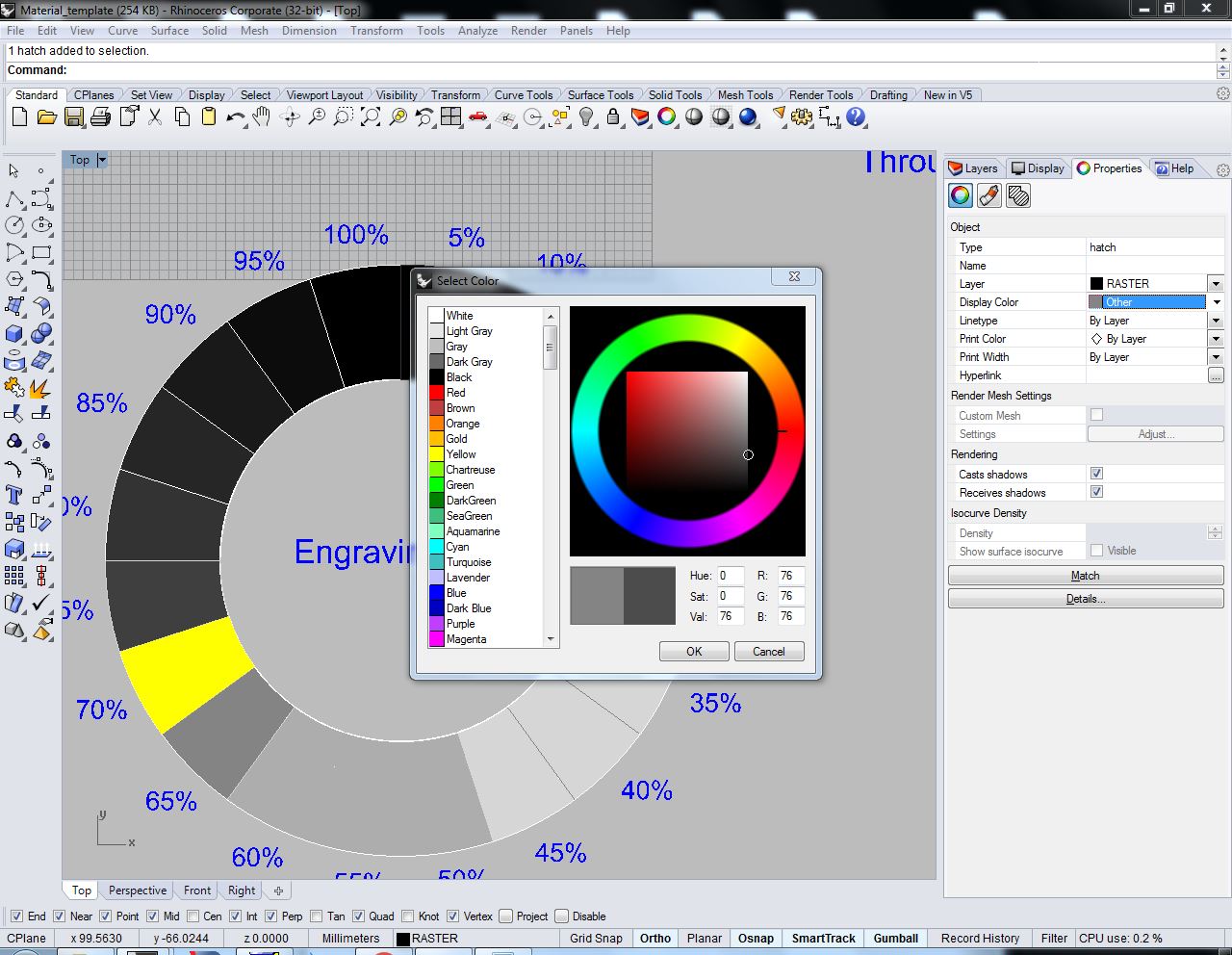
In the same workspace, the cutting area must be setup, as well as the printing settings, to define the material and thickness of the board. And then we set one color/layer for each laser process, and define which lines correspond to each process/layer.
The order of colors is defined by the command list on the JobControl software. The order of the workflow should start by the rastering (layer in black), then inner cuts (layer in blue) and then outcuts (layer in red). We are working from the inner part of the layout to the outter parts.
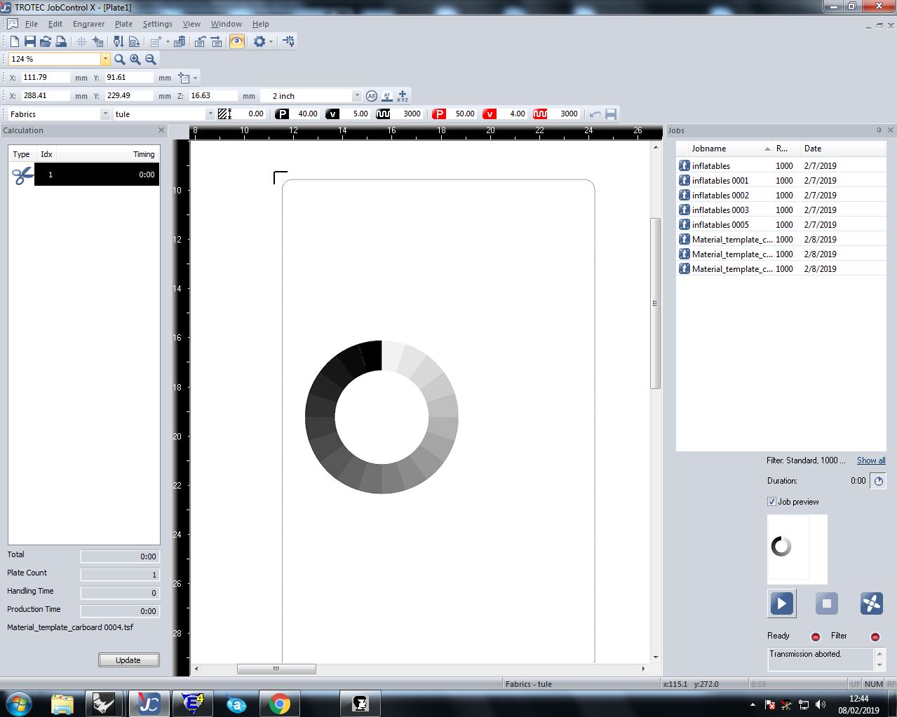
Now that all printing settings are ready, after defining the material area where we are going to work, we select Print and the JobControl CAM software will pop-out. On this software we should select the latest file that appear on the list on the right, and the preview will appear on the working area in the middle.
We must be sure that the file is the correct one and the different colors for each process are visible on the small preview on the lower-right part of the screen. Then on the top menu, we select material settings on the setting menu.
Then the material to be cut should be placed on top of the cutting board, aligned with the upper-left corner where the laser focus is set as origin. If necessary, painter tape may help to stick the board flat to the borders to avoid from bending, because it would affect to the cutting efficiency in terms of power.
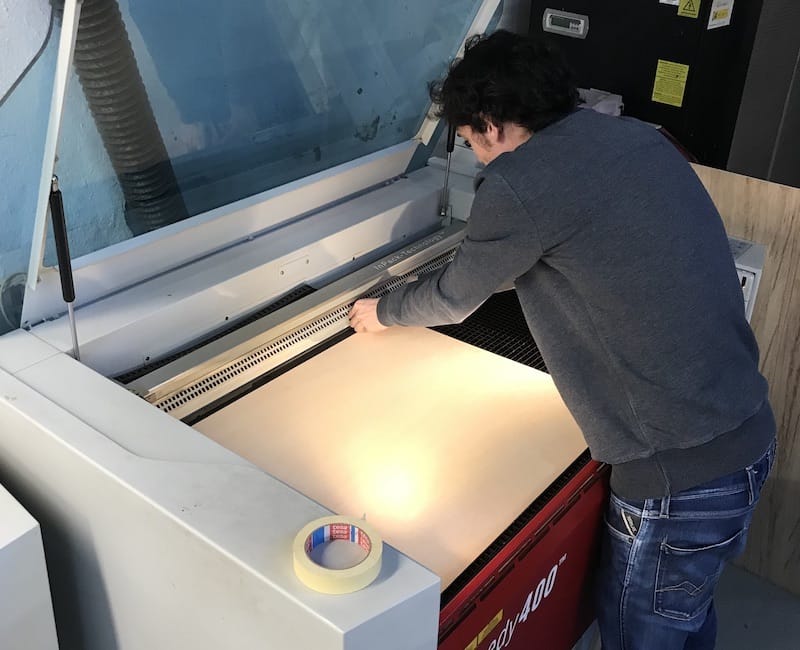
Before starting the machine, we must be sure that the air extractor is on, and also focus the machine with the caliber piece shown below.
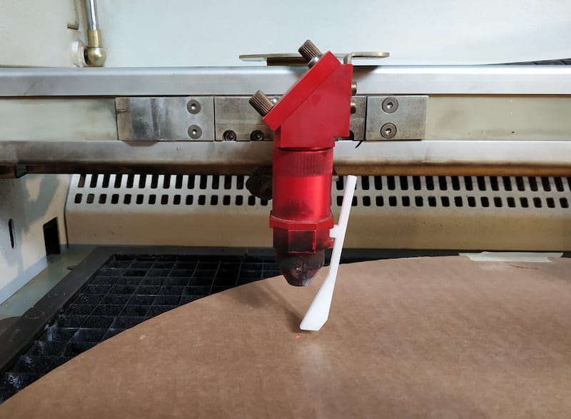
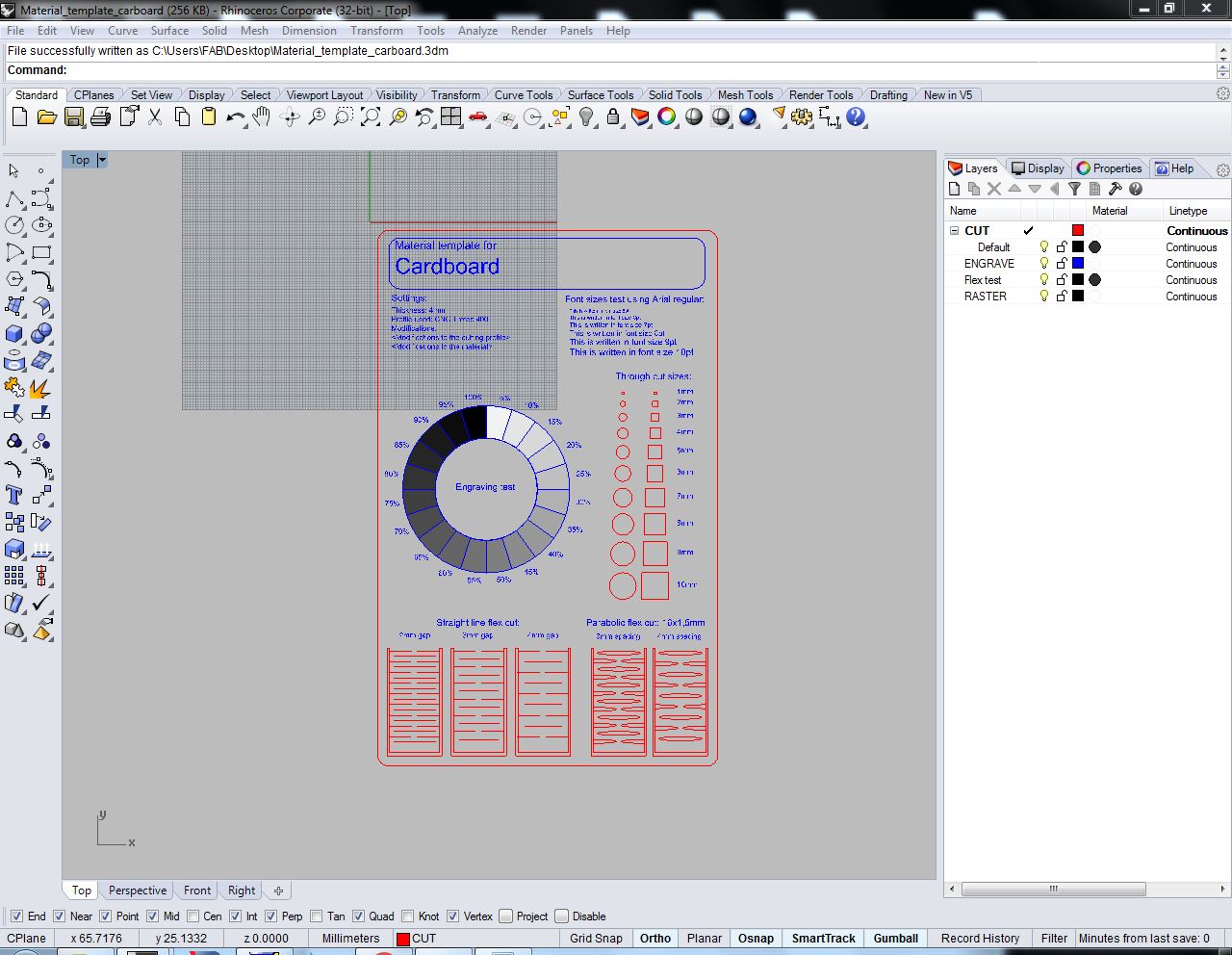
These are the first testings made in cardboard (4mm) and plywood (4mm):

The setting used for the different processes are the followings:
Cutting:
4mm cardboard: 50 (Power), 1 (Speed), 1000 (PPI)
4mm plywood: 75 (Power), 0.8 (Speed), 1000 (PPI)
Engraving:
4mm cardboard: 30 (Power), 100 (Speed), 1000 (PPI)
4mm plywood: 60 (Power), 100 (Speed), 1000 (PPI)
Rastering:
4mm cardboard: 80 (Power), 100 (Speed), 1000 (PPI)
4mm plywood: 60 (Power), 100 (Speed), 1000 (PPI)

Press-fit testing
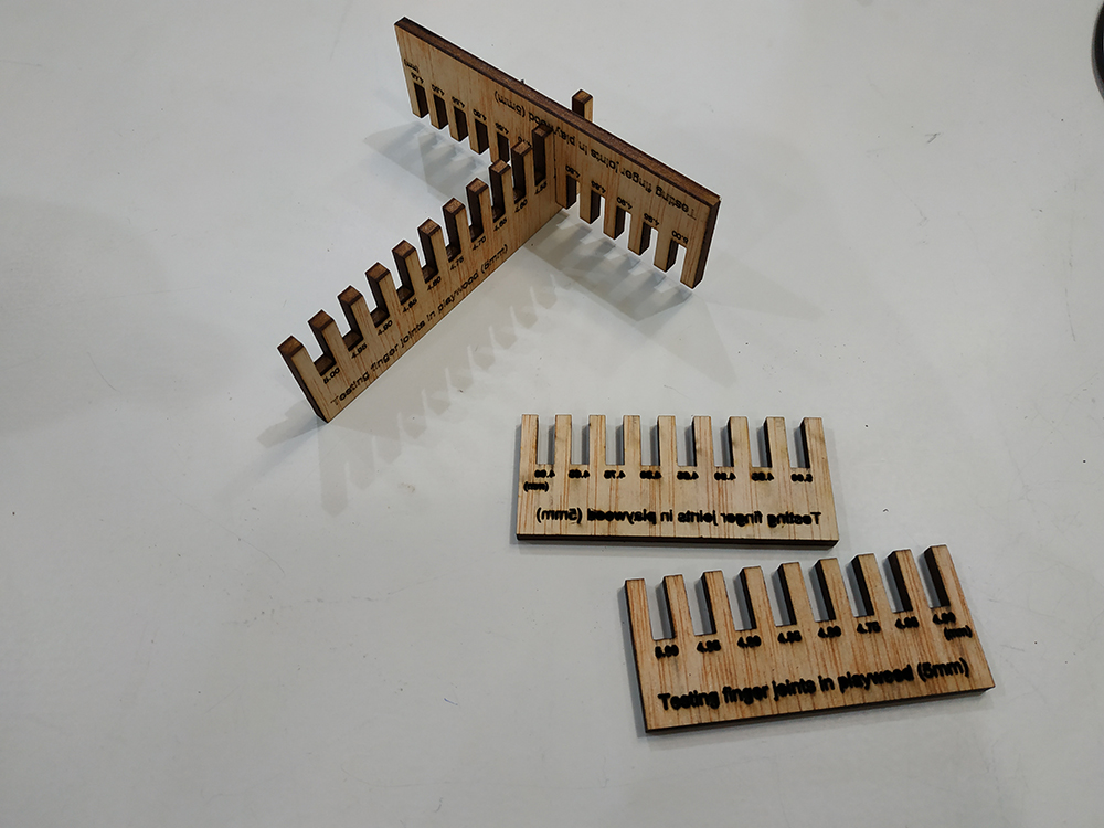
Then we made a press-fit test.
The best results for plywood was the 3.85mm gap and for the cardboard, 3.35mm. The difference is due to:
- The cardboard had a bigger kerf. Maybe just because the material burns more easily. But we believe it may come from laser being over powered.
- Cardboard squeezes way more than plywood. Fitting in tighter gaps.
4.2. Individual Assignment
For the individual assingment I will work with both laser and vinyl cutting machines.
4.2.1. Individual Laser Cutting
For the laser cutting assignment I chose to make a parametric clipping joinery to test with acrylic plastic. Acrylic is a very nice material to cut with a very good finishing, specially as a transparent material, but it can be found in different colours and optics.
We were asked to design a press-fit connection, and here there is interesting info about it.
Therefore, I will be working on the design of a modular piece that can be stacked in different directions to create volumes out of 2D planes. In this case I will work with Fusion360 to try its parametric functions along the design process.
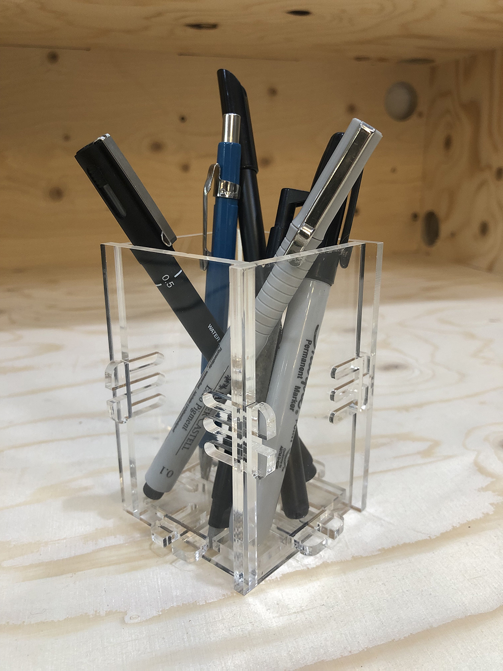
I decided to make a pen holder with this mechanical joint.
I found this work from a FabAcademy alumni that inspired me quite a lot.
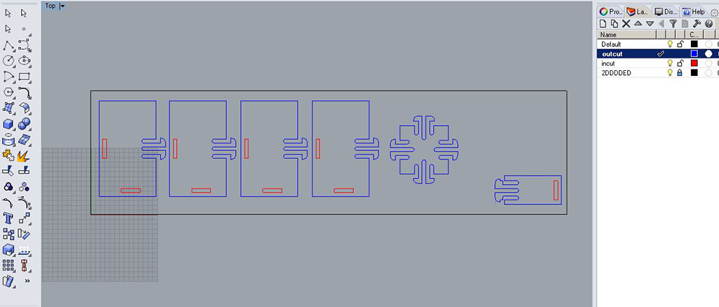
So I first started designing the piece on Rhino as a 2D drawing and applied the layer settings on every line (red for incuts, blue for outcuts).
Then I saved the 2D drawings as dxf file to import it later on Fusion360.
TESTINGS
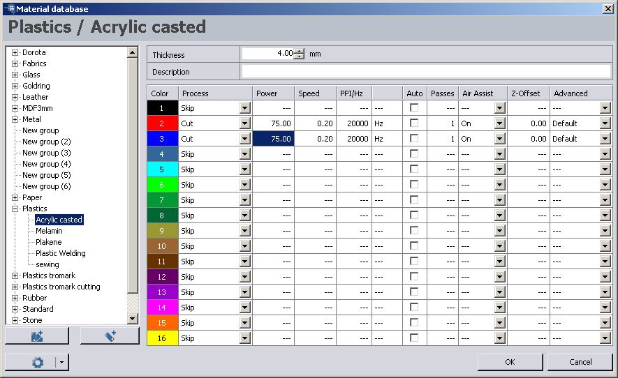
Then I configured the material settings on laser cutting's software JobControl. Normally I use the Trotec Speedy400, so I would have used a 75(power) 0.5(speed) and 20,000 Hz; but I switched to a smaller version of the laser cutting machine: Trotec Speedy100R. As this machine works with lower power, I had to reduce the cutting speed to 0.2., and this gave me slow but very good results.
And these were the results of the testings, using diferent tips for the clip.


Once I got the final measurements, and having tested different tolerances and clip-heads, I cut all the pieces.

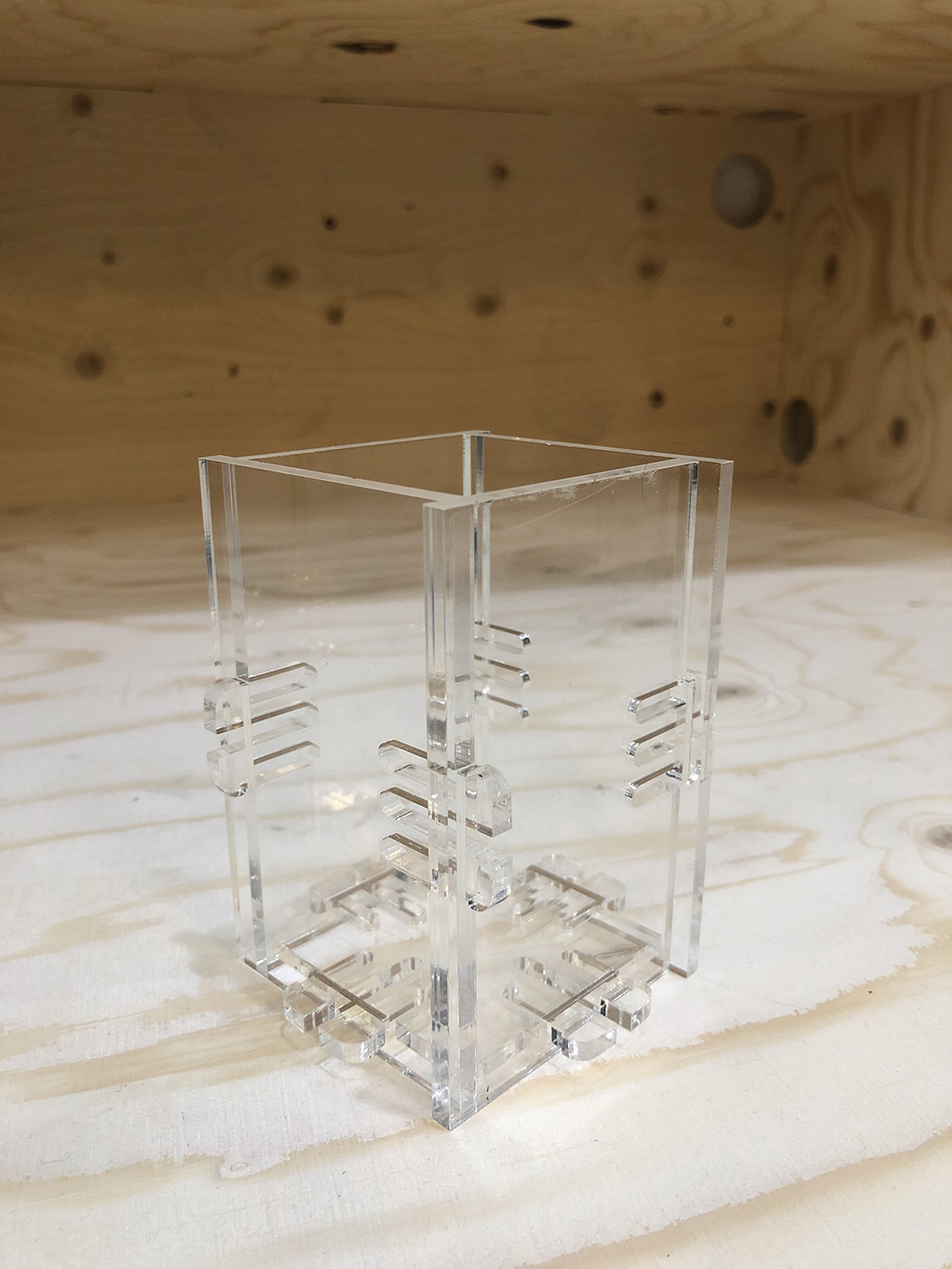
After assemblying them, this was the ultimate pen holder:
Using parameters on Fusion360
I found an interesting tutorial where explains how to design with parameters in Fusion360.
Here it is stated that parametric design is a process based on algorithmic thinking that enables the expression of parameters and rules that, together, define, encode and clarify the relationship between design intent and design response.
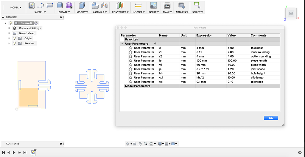
There are user parameters (defined by the user) and model parameters (created automatically by the software). It is very useful then to create a table where we define the parameters we want to work with along the design process, and then reference them on the drawing or function dimensions. In my case, I set a relation between the inner rounding, joint space and clip length parameters, and the piece's thickness, hole height and joint's tolerance.
To start with the parametric design on Fusion, first I need to import the dxf I designed on Rhino. So I will simply select the Insert DXF option on Fusion from the Insert manu list, select the Plane to place the sketch and the DXF file with a 1:1 scale.
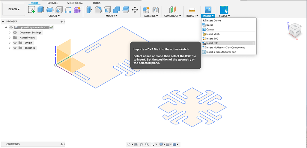
I will create a parameters table that will include every element dimension with a name, expression and value. This option is available on the Modify menu:
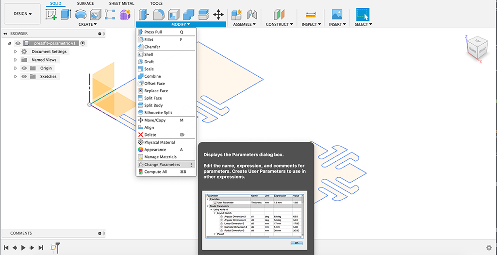
This is the table I made according to the parameters I needed:
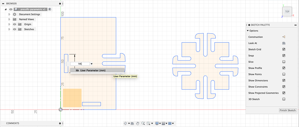
Then I need to change the dimensions on the sketch by right-clicking on the dimension and write the parameter name according to the table I created. In this case, I changed the '20mm' dimension by the 'hh' (hole height) expression. So that any time I change its value on the table, it will be automatically modified.
4.2.2. Vynil Cutting
For the vinyl cutting assignment I grabbed a bunch of logos that I designed sometime ago, and I also downloaded some other free OS models from the noun project. I can download thousands of models in svg or png format that I can modify myself, rescale, change paths, etc.. on Illustrator. So these are the ones I chose to make the testings:

Then I create a file on Illustrator where I place all the drawings trying to fit in the smallest space for cutting. I mixed many different types of models, all of them vector images, closed paths, but with different sizes and space between the cutting lines. I want to force how precise the machine will cut small dense drawings.
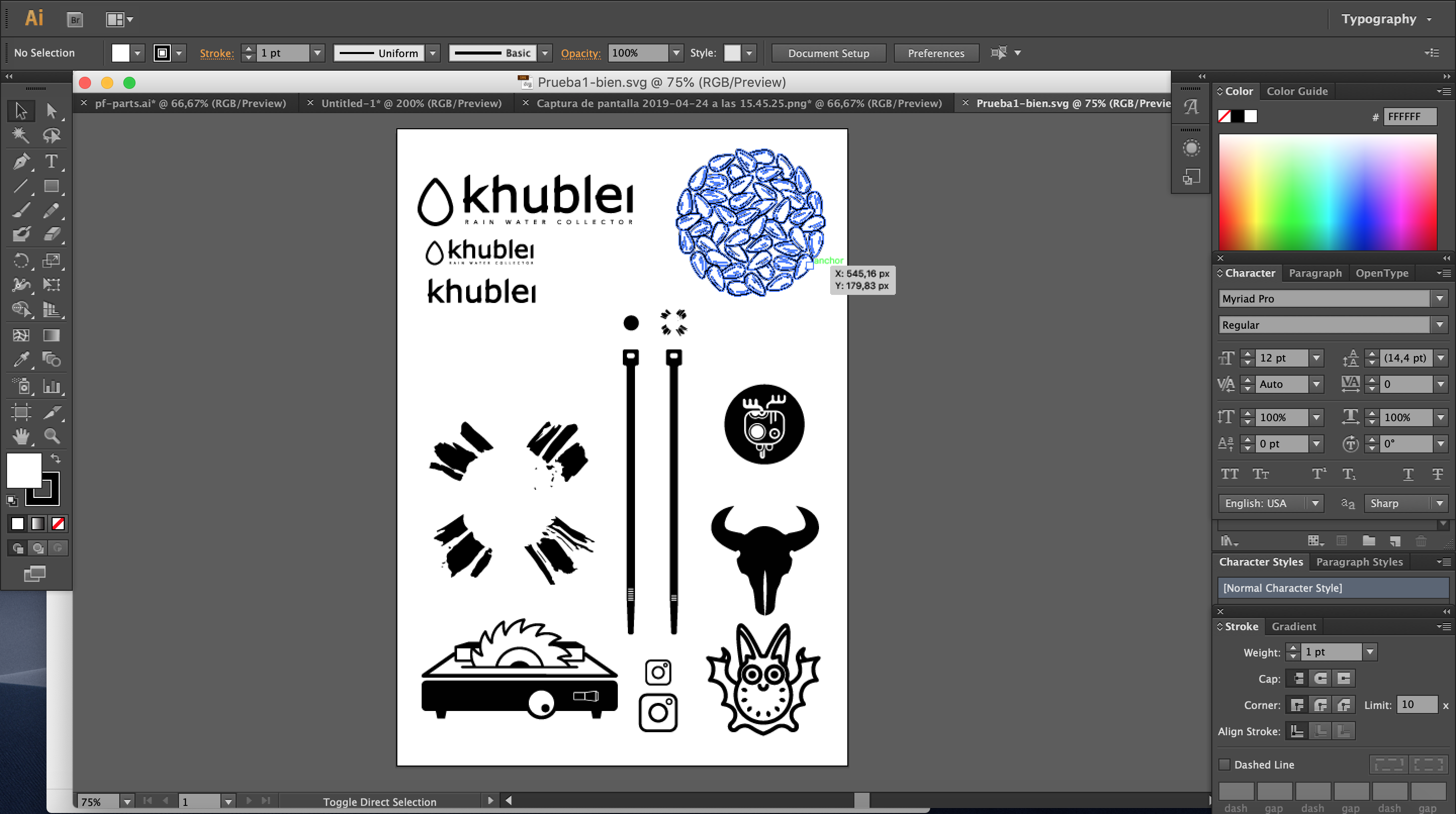
When everything is placed and ready, I save the file on Illustrator 3 (2004/2005/2006) to open it with the vinyl cutting software: Silhouette Studio 4.
Then we introduce from the front a piece of black matte vinyl, and after pulling a pedal on the backside of the machine, the roller parts that fix the vinyl to the mechanism, we adjust the piece of vinyl to be parallel to the cutting line, and pulling back the pedal ensure it is well trapped. Then on the screen of the machine we can select an automatic measuring that will calculate the exact size of the piece.
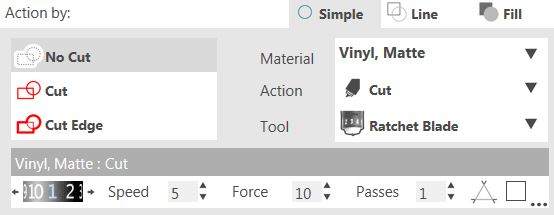
Back into the Silhouette Studio, we should see our layout in red. Then on the right part of the screen, as we are using just one tool/blade, we select a simple cut.
And we can grab the vinyl's size just from the machine on the cutting settings. Before anything, as in all machines, it is highly recommended to make a small test on one edge of the vinyl just to be sure that all settings are fine and we won't waste any material. And we press 'Send'.
The machine will start cutting quickly. It took around 15 mins to cut my piece of vinyl (around 30x30cm), but there were some very dense drawings like the sunflower seeds, that had hundreds of small cuttings.
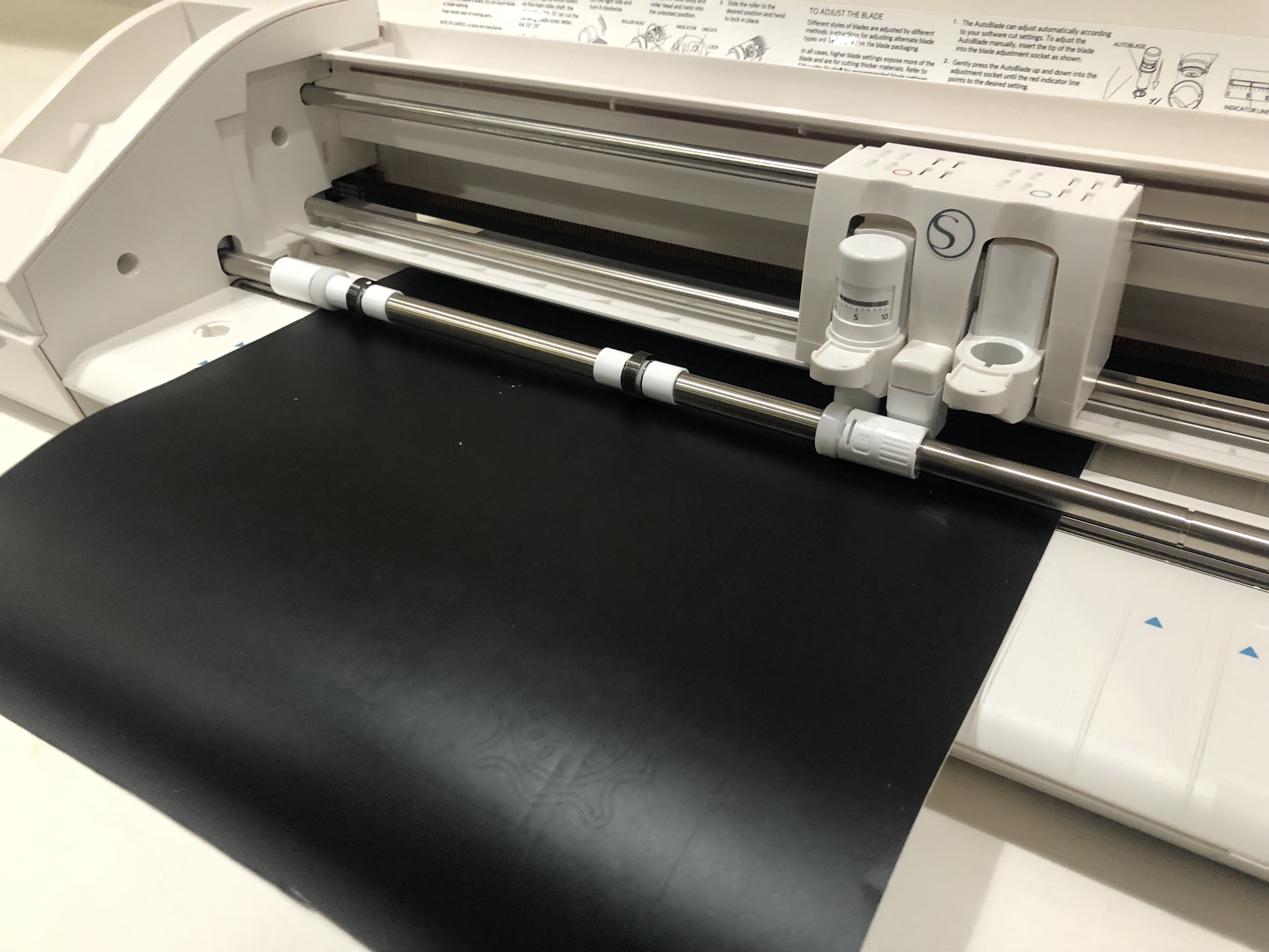
The best way to remove the cut parts, is to extend the vinyl on a flat surface and remove the parts softly with the help of some tweezers. If it is a set of small pieces you can use painters tape or transfer paper to create a layer where all the pieces will get stucked and keeping the exact position, we can transfer elsewhere. That is very common with vinyl text or lettering.
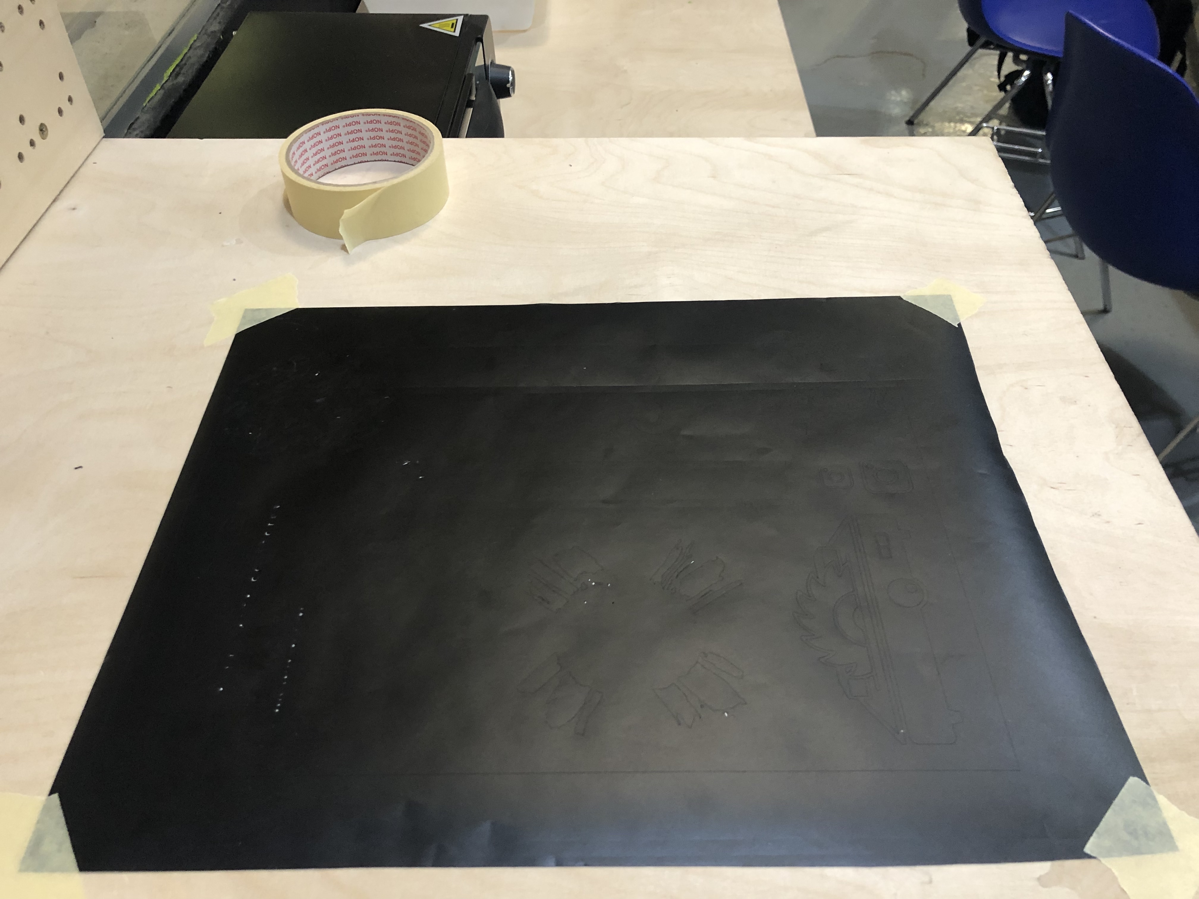
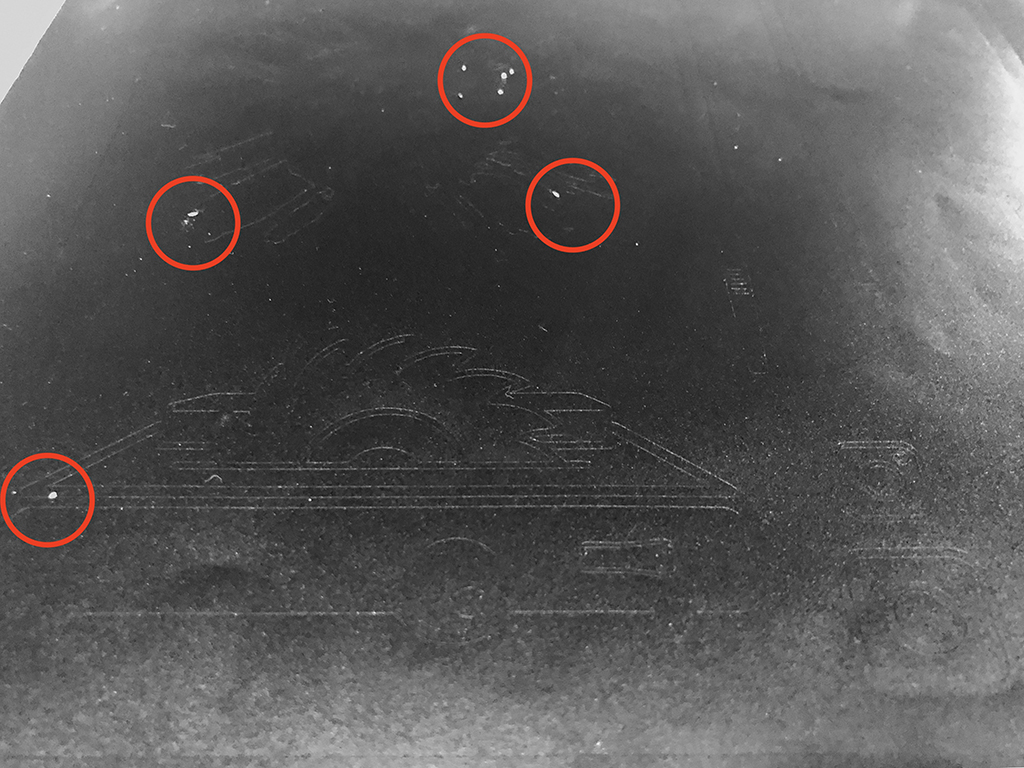
The smallest details failed on cutting and were almost impossible to remove.
I tried with other colours and finishings.
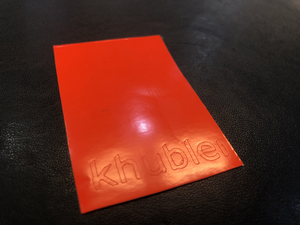
In this case I used a fluorescent orange shining vinyl.
For the process of placing the vinyl it's very useful to work with some twizzers to hold and pick the smallest pieces, and painters tape to transfer the pieces from the vinyl to the final placement.
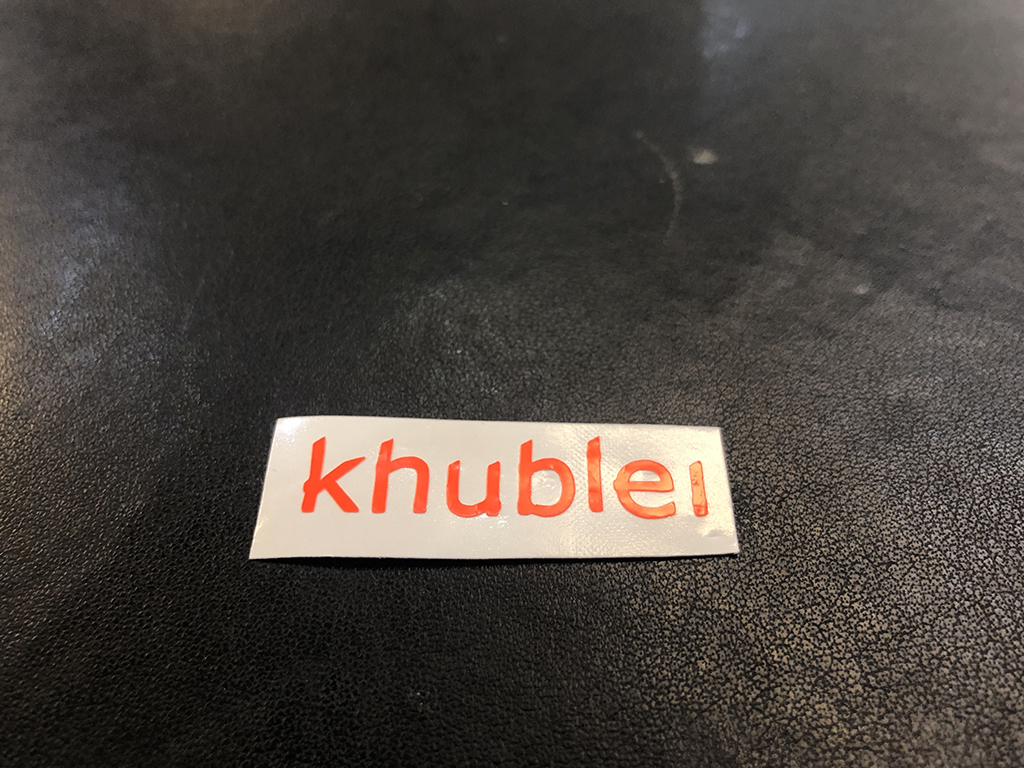
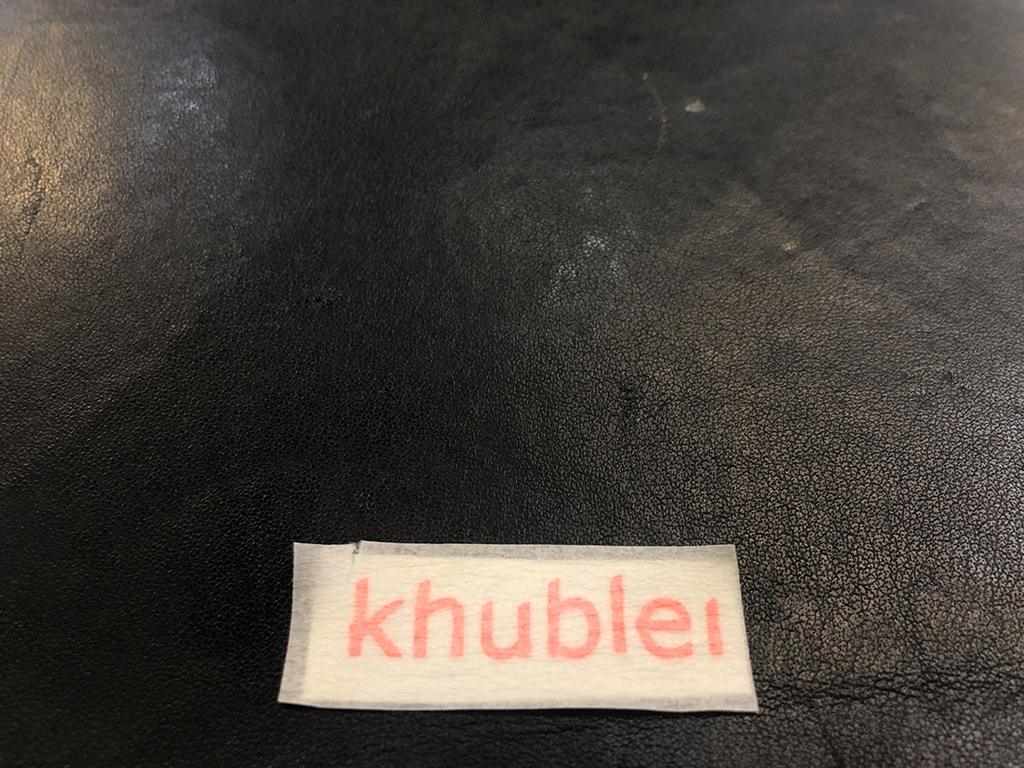
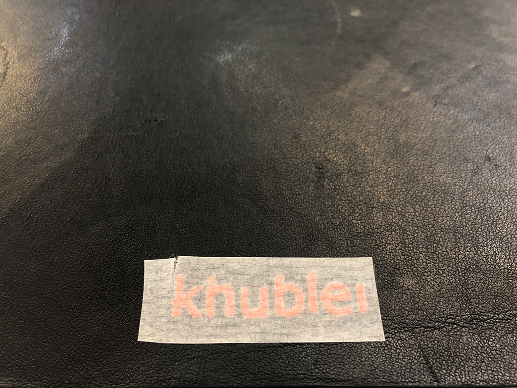
It's important to press and scratch over the painters tape to make the vinyl stick onto the surface firmly. Then, remove carefully the tape and see the results.
You can download the files here.

