Computer-aided Design and me
In this second assignment, we are introduced into computer-aided design (CAD). My experience among this field is quite close to different 2D and 3D designing tools. These are some of the softwares I used specially for product design, technical drawings, mechanical and mechanism testings, renderings and and graphic design (logos, illustrations, schematics).
2D Design
- Adobe Illustrator (WIN/MAC). I normally use this software for graphic design, specially to work with vector images such as png files, diagrams, logos, even sometimes to edit technical drawings that are easily scalable and resize any vectorial lines or paths. You can quickly give your layout settings (depending on the final use, for printing, web, slide, video), so that you can work with different units and working areas. Then once the work is over, you can save your file or export it in several formats (ai, jpg, png, svg, dxf, dwg, pdf, eps, ...) to work on with other softwares.
One of the best tools in this software for me is the image tracer, or the way to turn bitmap images or text into vectorial elements, or rasterizing the way back.
- Adobe Photoshop (WIN/MAC). This other popular Adobe software is so useful to me for graphic design, but in this case with raster images or bitmaps. The way of working by layers, folders, and many further specific photo editing tools, makes it such a versatile software to work with. Also when you need to set a specific image or canvas' size/settings/bitrate.
- AutoCad (WIN/MAC).I used to work with AutoCad for some space design, or big scale technical drawings to show proportional or scaled views and details. Working with preset pen settings or box templates will make much easier to set the drawings into any printing layout.
3D Design
- Creo Parametric (WIN).
- Solidworks (WIN).
- Rhinoceros (WIN/MAC).
- Blender (WIN/MAC).
- Sketchup (WIN/MAC).
3.1. Original idea
For this assignment I chose to redesign an old project I worked on 4 years ago. The project was about designing a chair made of plywood pieces, with no glued or screwed joints. The original idea considered to design a chair out of a sphere by volume substraction turning the chair into a 360 rotation rocking chair. The first model was designed with Creo Parametric software and rendered with Keyshot. Here there are a couple of renders of the original idea:

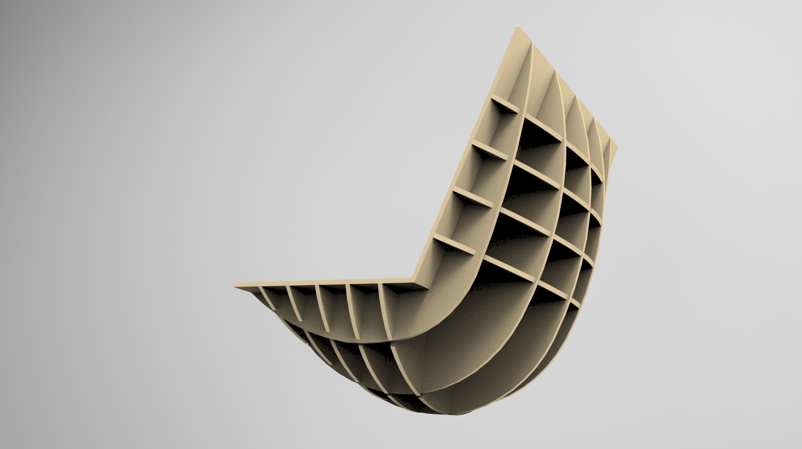
Mockup pictures
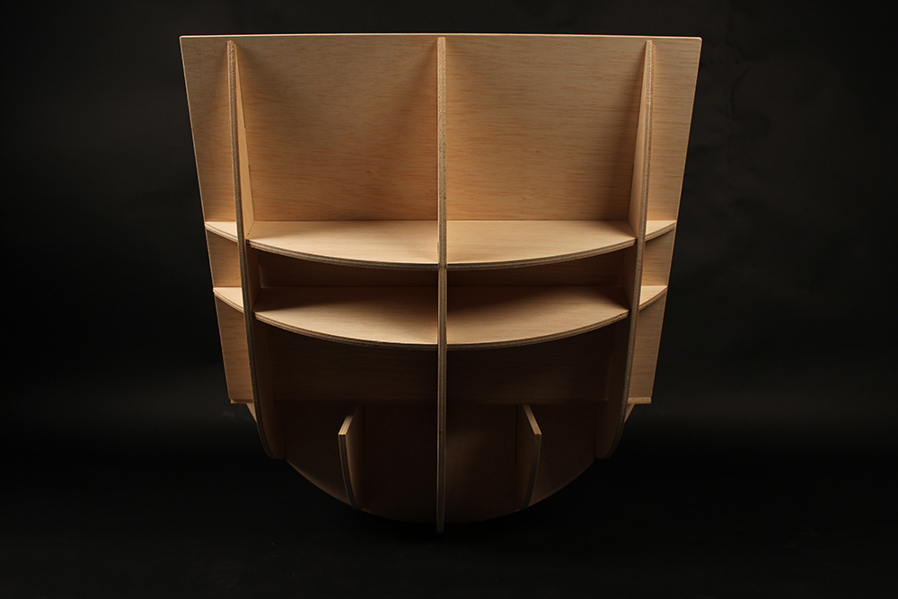
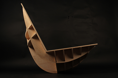
After designing the CAD model, I built the rocking chair in 5mm Plywood boards by cutting the pieces with a CNC machine. These are some pictures of the original mockup:
3.2. Designing in Fusion360
For the redesign of the model I decided to use Autodesk Fusion 360 software. I found it interesting to use a new CAD (parametric) software that could be ran by Windows and Mac computers (as I work with a Macbook with a WIN/MAC partition, I need to switch from one OS to other whenever I need to work with CAD softwares as most of them are operated with Windows).
I also found interesting the wide variety of plugin softwares of Autodesk easy to link to Fusion360 projects such as Eagle (electronic design) or Slicer (a slicing tool for designing infill or inner structural models).
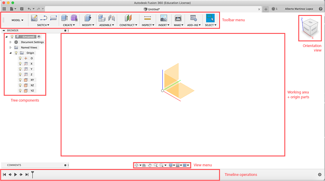
(Fusion360 interface)
Apparently, Fusion360's interface looks similar to other CAD softwares like Solidworks or CreoParametric, but later you can notice there are many many differences in showing things like the timeline actions, the components-tree, the toolbar menu, or even the options for saving in online or offline modes.
While designing models or assemblies it is important first to understand the nature of parts differing between bodies and components. This aspect will define the model as a whole (body) or divisible in parts (components), so the material properties, or geometrical definitions can affect to the whole model or just the selected components.
But the workflow is very similar to other softwares. You start defining the planes on which drawing the first sketch, and then start creating volumes (extruding, revolving, swipping the surface generated in the sketch). Here I will show the process I followed to design my rocking chair built in a grid structure:
Sketch
First I am drawing a side section sketch with the dimensions of the chair considering first its ergonomy.
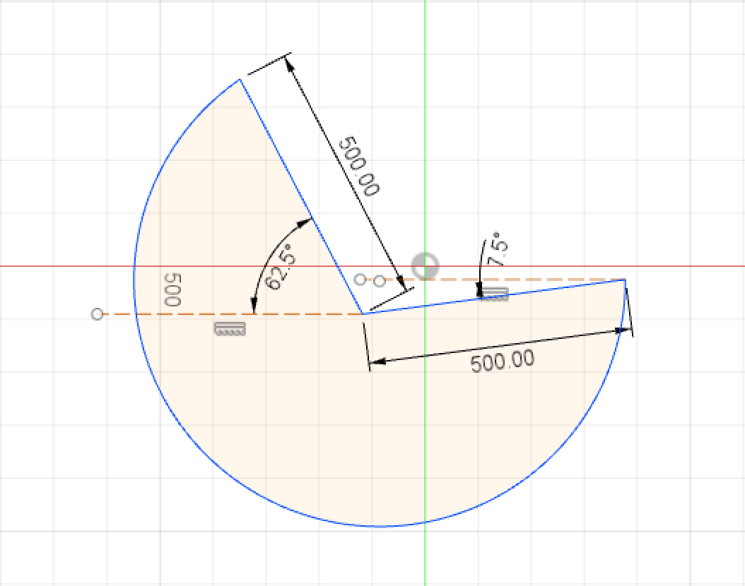
But the easy process of designing the chair will start creating a ball, which means revolving a semi-circle along its axis. So this is the first skecth I made:
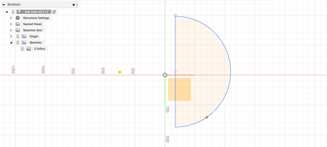
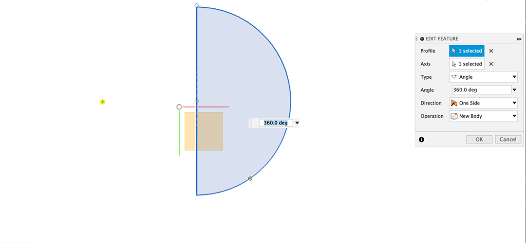
Then on the Toolbar, I selected from the Create menu, the revolve tool:
Then on the middle plane I draw another sketch that will be the seating space (bearing in mind the first sketch's dimensions). This sketch will be extruded as a symetric alltrhough cut.
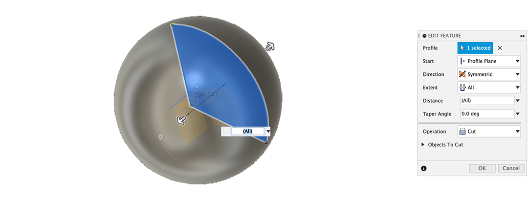
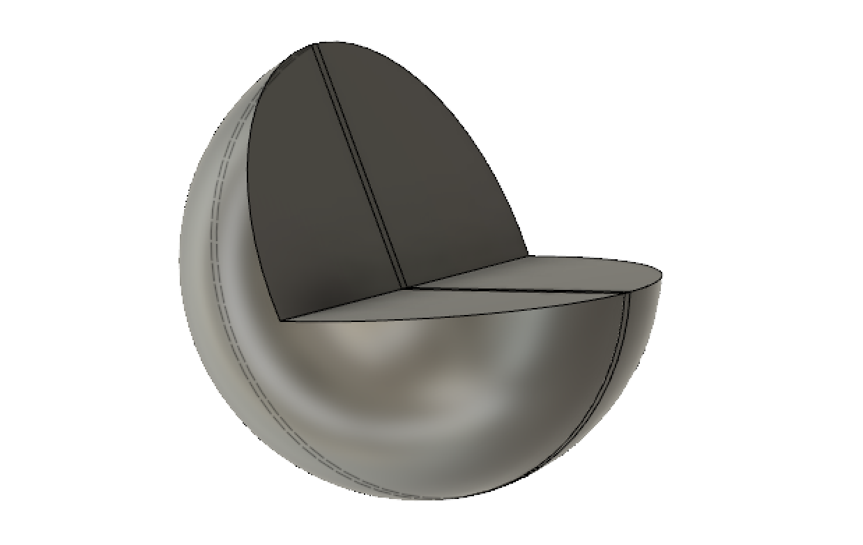
So this should be the final state of the model in Fusion, as a solid volume that will be postprocessed with the Slicer software.
3.3. Slicing the model with Slicer plugin
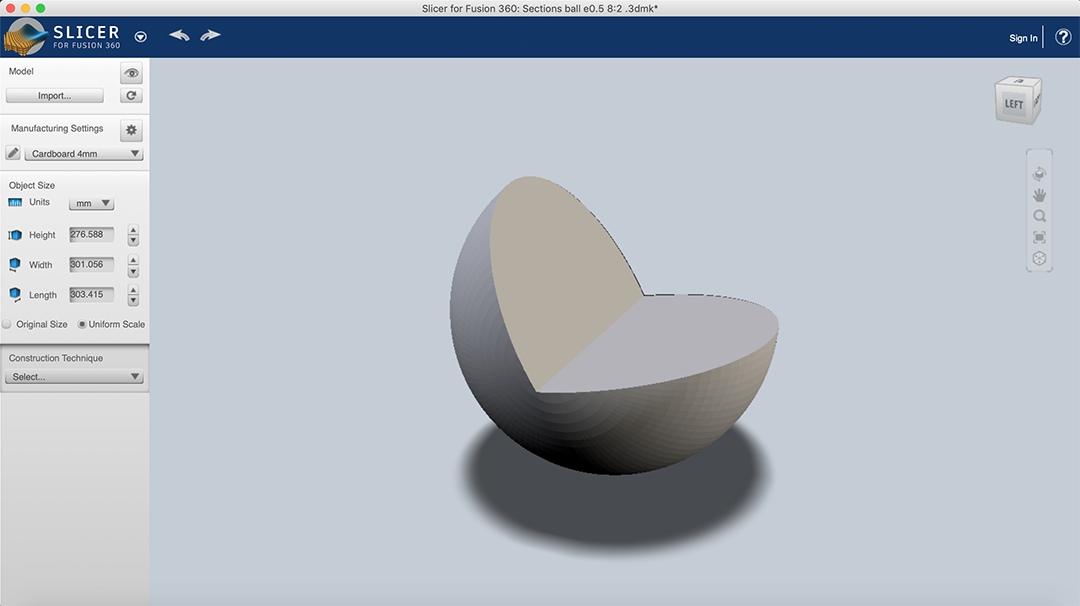
First, once we have Slicer open, we need to import the model designed with Fusion360.
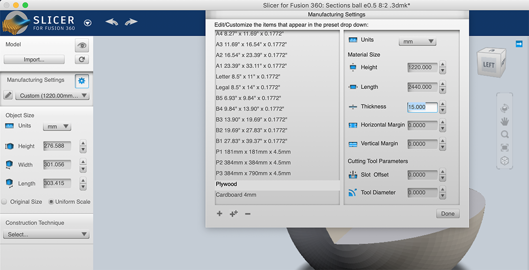
Then we choose the kind of material, its thickness, the original material format. In my case a plywood 15mm board (2440x1220).
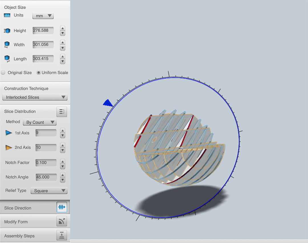
Then we select the way to create our inner structure. In this case I chose a squared grid , made of 9 vertical layers and 10 horizontal layers.
Moreover, you can change the different parts generated in the slicing, move, scale, turn and so (as shown in the picture below).
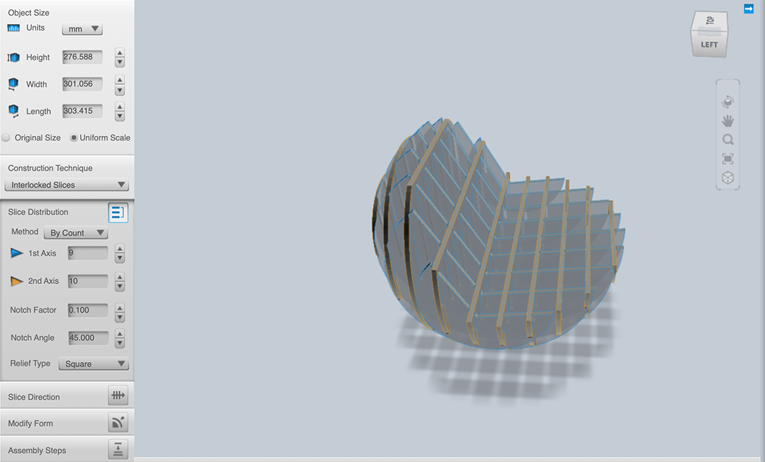
This way the model can be transformed into a sliced structure. The properties of the slices as well as its distribution along the cutting panels are calculated by the plugin software.
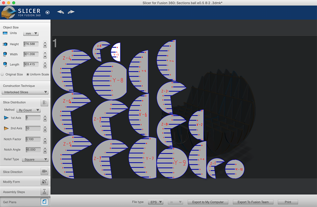
Once we are fine with the results obtained with the software, we can get the plans of the pieces to create directly the cutting file. You can get the plans in dxf, dwg or pdf format so that you can edit the drawings further with other software.
3.4. Section + center of mass calculation
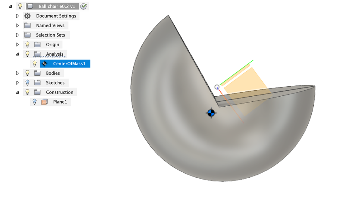
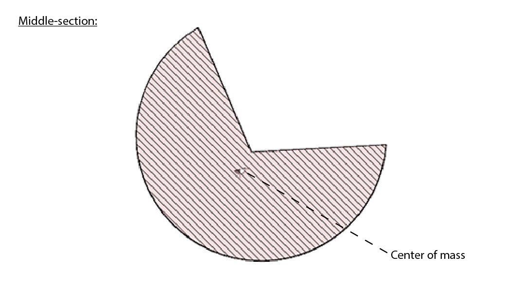
Its spherical base will demand a center mass calculation to guarantee its stability, and this is a good chance to discover new tools from the software. Center of mass point and middle-section of the model are shown in the following picture:
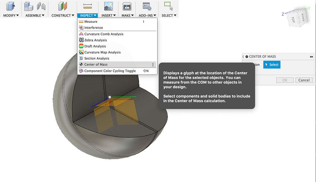
So again in the Toolbar menu, I select Center of mass inside the Inspect menu.
3.5. Laser cutting layout distribution
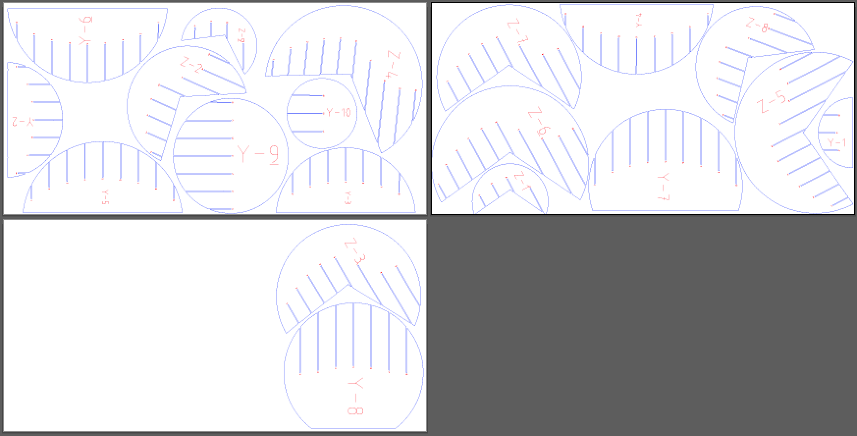
This layout shows the distribution of all the pieces in 3 plywood panels (244x122cm). The distribution of the pieces was readapted in Adobe Illustrator to condense and reduce as much as possible the space between pieces.
3.6. Anemometer design (final project)
Here I will explain my final project's anemometer design:
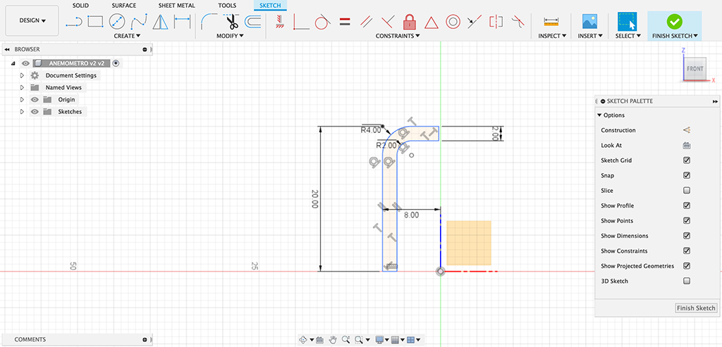
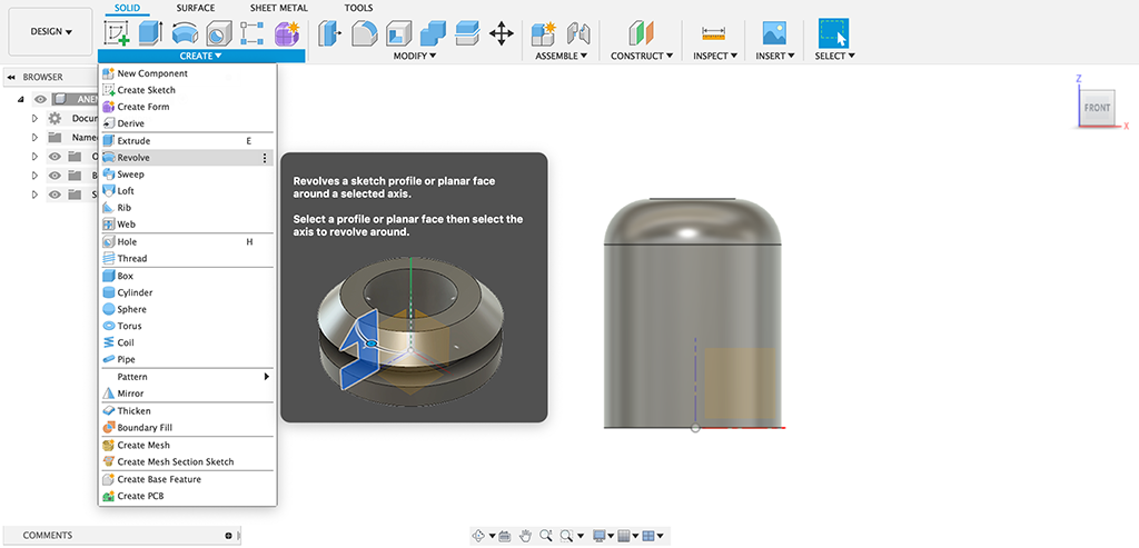
I will start with the central base in the middle, selecting the lateral plane and drawing the section I will revolve later to create a cylinder.
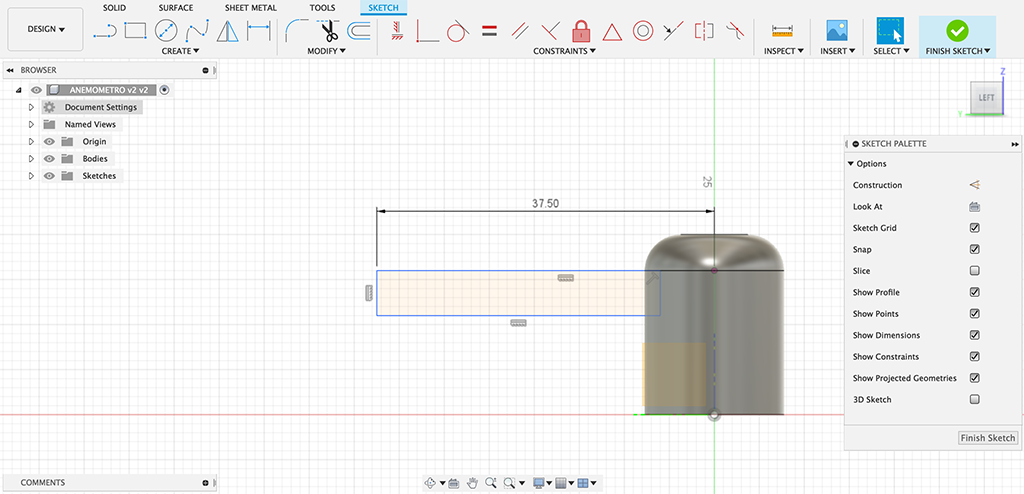
Next step is defining an anemometer's arm, so I select the lateral plane to draw a sketch that I'll extrude symetrically later:
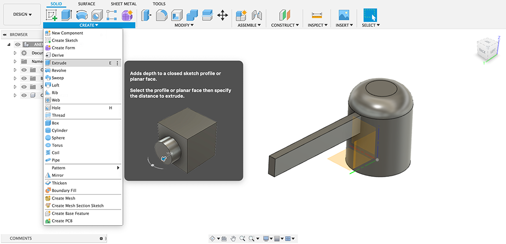
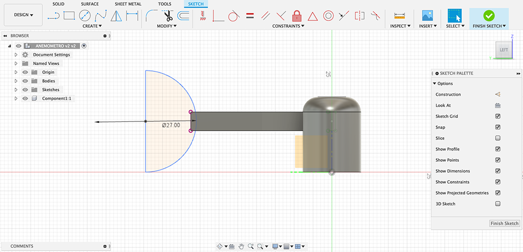
To design the anemometer's scoop, I will first design a semicircle at the end of the arm to revolve it later and make a sphere using the same revolve function:
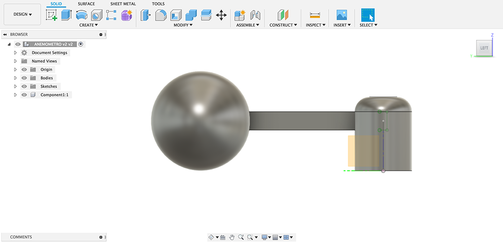
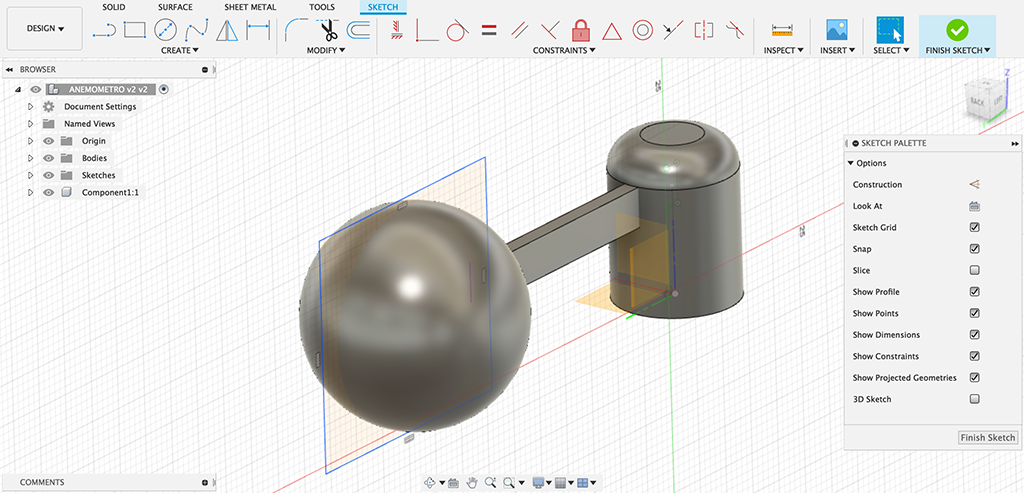
To get the semisphere, I just need to remove half of the ball, so I will draw a square (bigger than the sphere) on a plane over one of the arm's side and make a cutting extrusion:
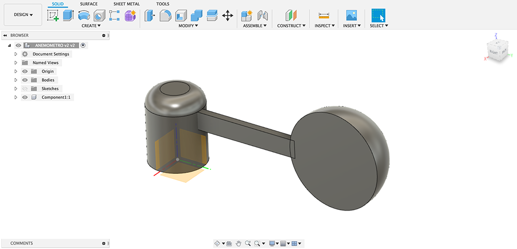
Then I'll make a shell from the semisphere I got of 1mm thick:
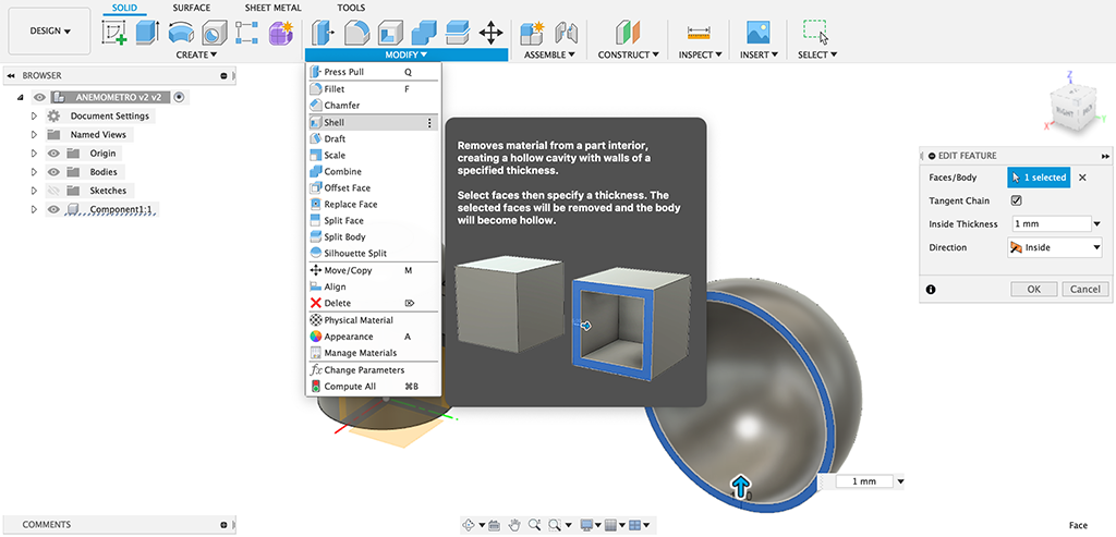
As part of the arm is inside the semisphere, I need to split the arm and remove the leftover part:
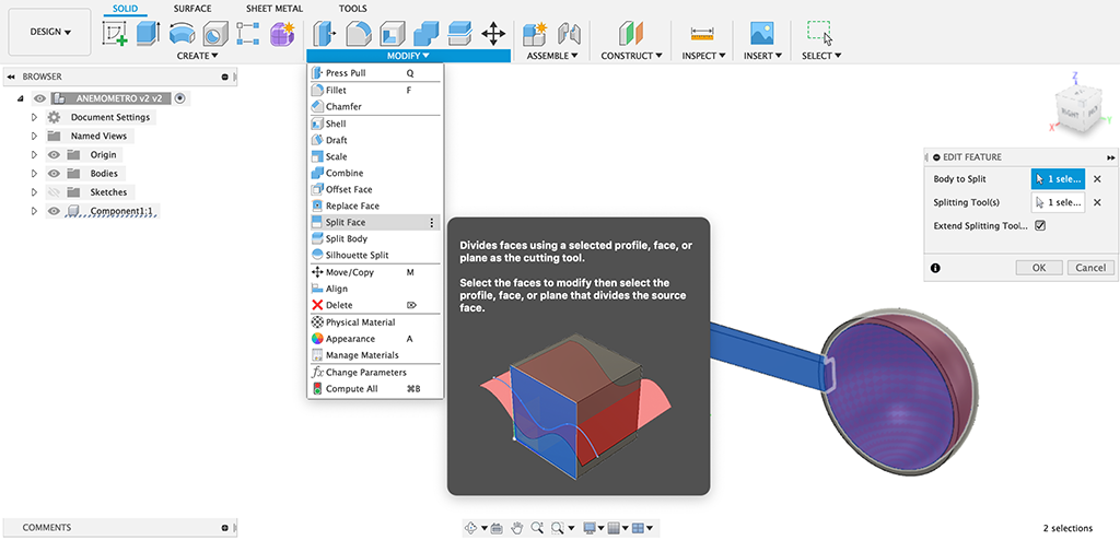
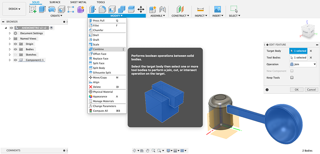
Once I got the final bodies, I will join them as one to make a single part with the Combine function:
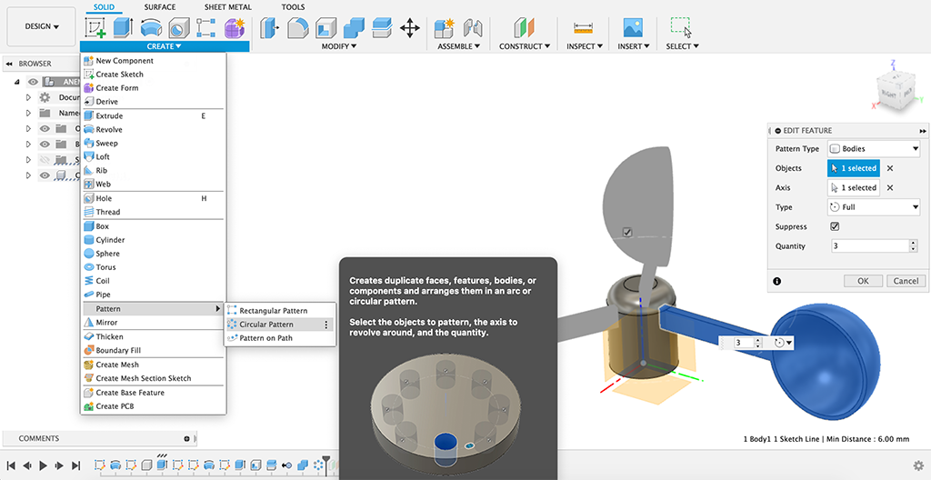
Now that I have this last part finished, I can make a circular pattern of it with 3 elements around the piece's central axis:
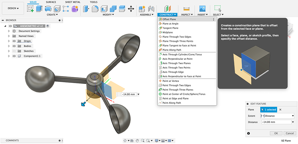
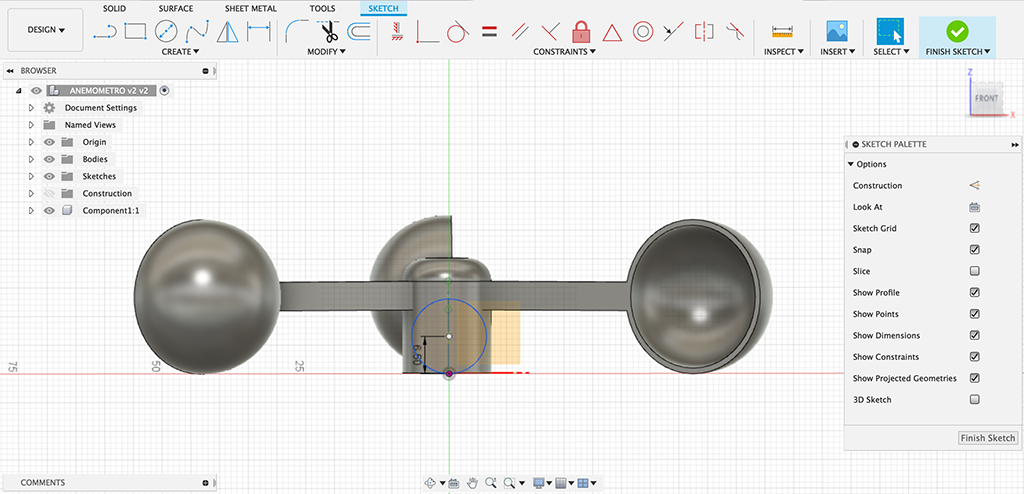
Finally I just need to make the room to keep the magnet that will activate the hall sensor circuit inside the anemometer. I am starting creating an offset plane to draw the circle where the magnet will be stucked:
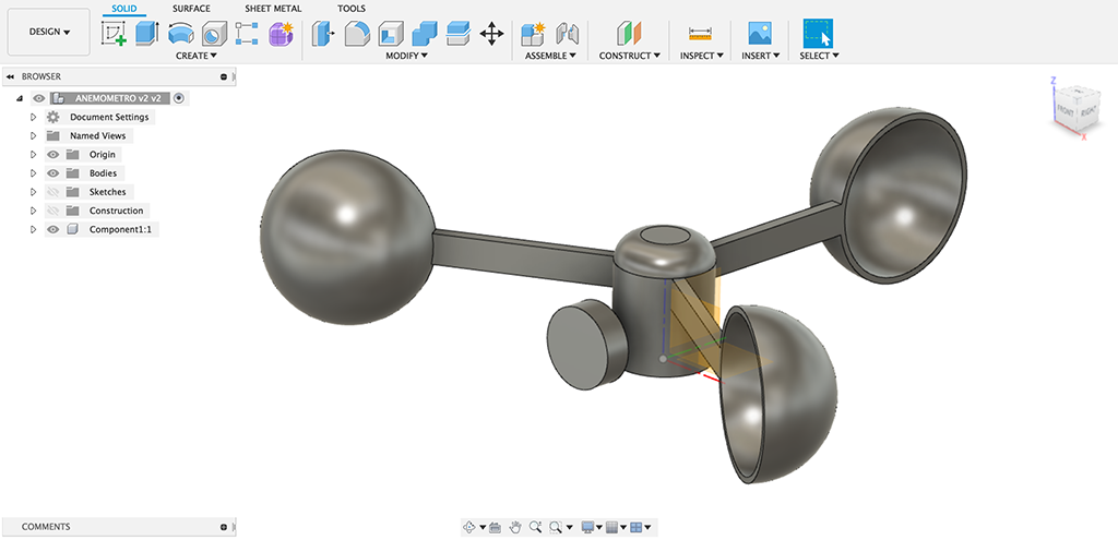
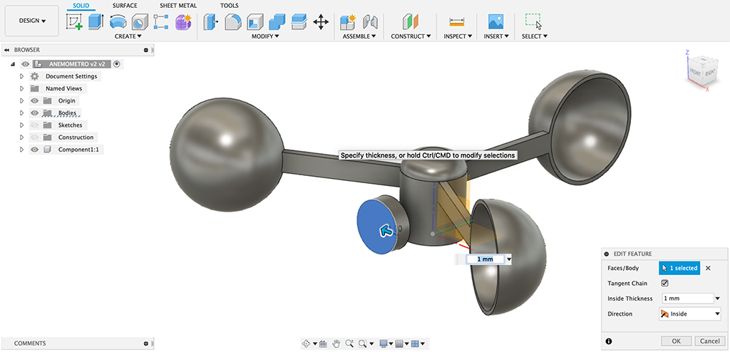
Then I create the shell to make the magnet's room:
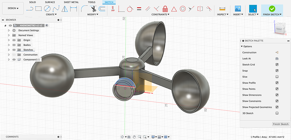
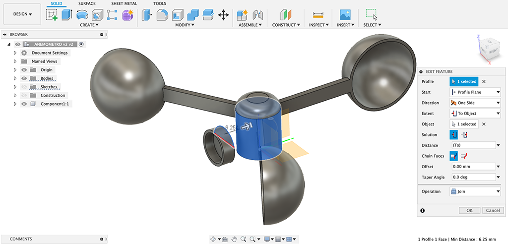
The last thing I should do is connecting the magnet's room with the anemometer's center by creating a semicylinder piece that I will extrude from a semicircle as shown below:
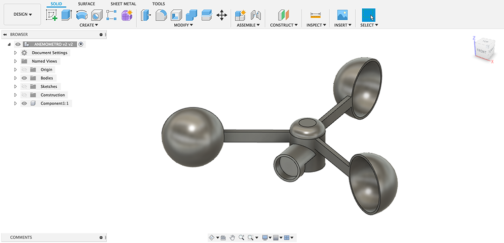
This is the final result ready to convert to stl as 3d printing file:

3.7. Files
Here you can download the files.