Machine Design

It was of the week where we basically as a group project had to do following things

Recaptulating Older week

We were working on 3 machines-

Updates On Hector /Challeneges

Hectors assembly was Made but the electronics were to be out sourced and we are still at developing stage for the automation of the hector

MTM Snap Updates

For the motion the main focus was to learn to operate or interface stepper motors,with the drivers and ramps.
The first thing I tried was to move the stepper motors and learn How it works- My role was to work With Rajat Sir helping him Out in the electronics and to debug the codes and learn about GRBL firmware.
We had very less time for the presentation so we took a pace in our work.. So I started with understanding the working of stepper motors. Then I moved ahead towards its drivers. After this i learnt about interfacing both of these components with arduino and then finally learnt about RAMPS board.


I learned that the steps are actually the motion of the rotor in the coils and its 1.8 degree per 1 volt.
But it's accuracy can be achieve by using the microstepping, and usage of motor drivers, as the stepper need oputput supply.

Actuation


After going through some pages over the internet i got to know that there are many ways to actuate a stepper motor like it can be actuated using ULN 2003a(Darlington pairs) IC or through L293D Motor driver IC or using A4988 Motor Driver. A lot of people have faced heating problems with ULN2003 and L293D do I first learnt about A4988 Driver IC as its not that expensive and was available in Lab . So here’s a video I refered for understanding and using A4988 driver IC with Arduino.
The simple code for driving stepper motor-
                                   

                                 *    https://howtomechatronics.com/tutorials/arduino/how-to-control-stepper-motor-with-a4988-driver-and-arduino/  
                                 *  by Dejan Nedelkovski, www.HowToMechatronics.com
                                 *  
                                 */
                                // defines pins numbers
                                const int stepPin = 3; 
                                const int dirPin = 4; 

                                void setup() {
                                  // Sets the two pins as Outputs
                                  pinMode(stepPin,OUTPUT); 
                                  pinMode(dirPin,OUTPUT);
                                }
                                void loop() {
                                  digitalWrite(dirPin,HIGH); // Enables the motor to move in a particular direction
                                  // Makes 200 pulses for making one full cycle rotation
                                  for(int x = 0; x < 200; x++) {
                                    digitalWrite(stepPin,HIGH); 
                                    delayMicroseconds(500); 
                                    digitalWrite(stepPin,LOW); 
                                    delayMicroseconds(500); 
                                  }
                                  delay(1000); // One second delay

                                  digitalWrite(dirPin,LOW); //Changes the rotations direction
                                  // Makes 400 pulses for making two full cycle rotation
                                  for(int x = 0; x < 200; x++) {
                                    digitalWrite(stepPin,HIGH);
                                    delayMicroseconds(500);
                                    digitalWrite(stepPin,LOW);
                                    delayMicroseconds(500);
                                  }
                                  delay(1000);
                               

The Working of Motor


Understanding GRBL Firmware

Source~ Instructables
GRBL is a firmware for arduino boards(uno,nano,Duemillanove) that controls stepper motors and spindles/lasers. GRBL uses gcode as input and outputs signals via the arduino pins. Most industrial cnc machines uses parallel port controller that requires Those big purple connectors. Because GRBL arduino boards you just hook it up to a free usb port.
Grbl is compatible with all atmega 328 based arduino boards, meaning that you could use a uno or a nano but not the mega as its atmega 2560 based. The arduino mega is used in alot of 3d printer because of its more powerful processor but because of the relatively easy tasks of a cnc mill the arduino uno is enough.
To drive stepper motors you need some sort of driver. Some popular choices are a4988 and drv8825 for small motors like nema 14 or 17, but should not be used with more powerful motors like nema23 and higher. Its a good idea to stay clear of the easy drivers.
To connect your motor drivers and arduino you can use a pre-made board like the popular arduino uno cnc shield or build your own.
Here We use RAMPS

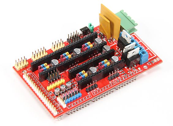
I followed this video to get a better Understanding

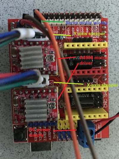
Detailed Interfacing-

  • 4 connections to the stepper motor, marked 1A, 1B and 2A, 2B. Connect the first coil to 1A and 1B and the second coil to 2A and 2B.
  • Logic Power and GND, Connect this to the GND and +5V of the Arduino
  • Dir sets the direction the stepper will move. I connected this to Pin 4 on the Arduino
  • Step will make the stepper step each time this pin goes form Low to High. I connected this to Pin 5 on the Arduino
  • Enable. When this pin is pulled low the board is enabled and the motor energised. When set high the board is disabled and the motor is de-energised. I connected this to Pin 6 on the Arduino
  • Sleep and Reset control the board, either sending it to sleep or resetting it. To use the board I tied these together which allows the board to run normally
  • Motor Power and GND. This needs to be a high voltage/current supply to run the motor. Note : Warning: Connecting or disconnecting a stepper motor while the driver is powered can destroy the driver. (More generally, rewiring anything while it is powered is asking for trouble.)
  • To prevent damage to the driver chip, it uses circuitry to limit the maximum current that can be used. This is set via the adjustable resistor on the board, in co-operation with some of the other components, the sense resistors (S1 and S2) and the resistor (R1). As different drivers may have different components (especially generic Chinese imports) its best to check these values before continuing.
  • VREF max = (TrimpotMaxR/(TrimpotMaXR+R1)) x VDD = (10,000 / (10,000 + 30,000)) * 5 = 1.25V
  • ITripMAX (effectively max motor current) = VREF / ( 8 x Sense_resistor) = 1.25 / ( 8 * 0.1 ) = 1.5625A
  • I started looking into GRBL and CNC shield as next step, Grbl is a free, open source, high performance software for controlling the motion of machines that move, that make things, or that make things move, and will run on a straight Arduino. If the maker movement was an industry, Grbl would be the industry standard.Most open source 3D printers have Grbl in their hearts. It has been adapted for use in hundreds of projects including laser cutters, automatic hand writers, hole drillers, graffiti painters and oddball drawing machines. Due to its performance, simplicity and frugal hardware requirements Grbl has grown into a little open source phenomenon.So i downloaded GRBL firmware and placed in Arduino libraries folder. The grblUpload.ino example file was uploaded in Arduino Uno. Below image shows the wiring done on the CNC shield. Before this wiring, the CNC shield was placed over Arduino Uno.

For detailed understanding of ramps I referred this document- https://www.reprap.org/mediawiki/images/0/06/RAMPS_dossier.pdf.


Testing ramps


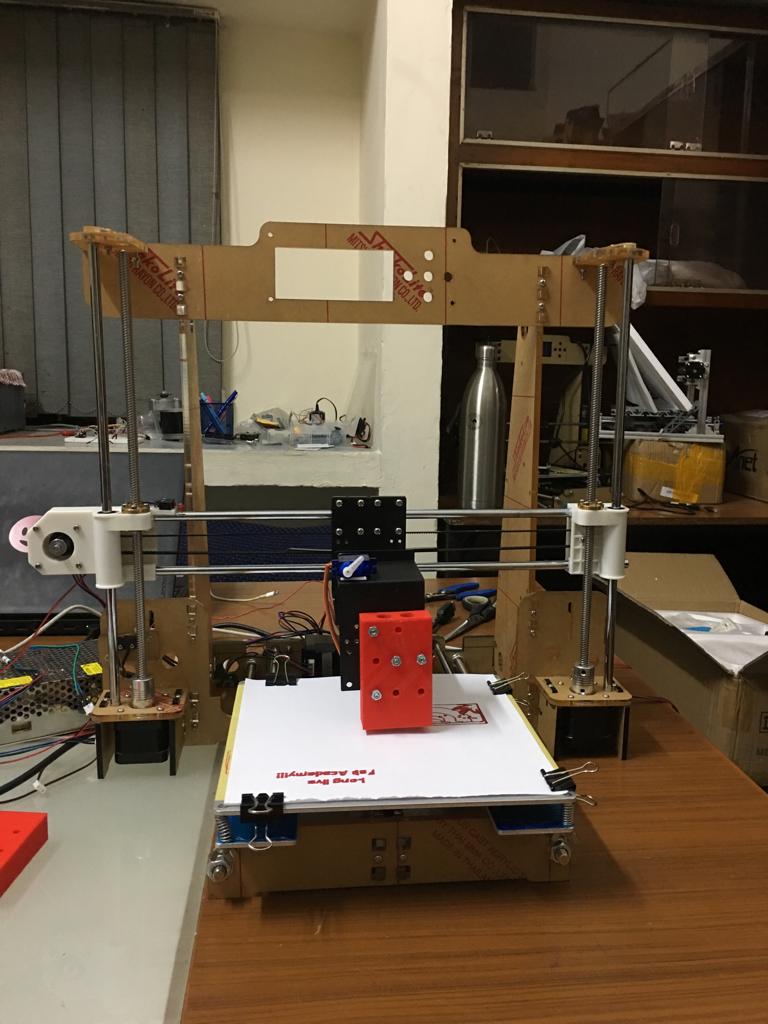
Wroking Of MTM with One Steeper Motor roatating the Linear Rod


Issues with the MTM Snap

Although Individually the motors was able to move the assembly but By the action of Load the assembly started drawing a Lot of current and the precise motion was not achieved. Both the blocks were unable to move simulatneously. The cause was that in Nadia's Assembly everything is made up of cardboard so there is very less load on the moving blocks on the linear rod, in our case it was mdf and also we didn't use any linear bearing on the other block we were just dependant on one Stepper motor with a rod assembly which was unable to do the work.
The issues was figured out but there was a lack of time so we all try and inested on our final presenatble machine the XY Plotter.

Conclusion

For final presentation and video and all the related files and codes. Please refer our-
Group Page

The final Machine is Plotter-
I used Arduino MEGA + CNC Shield + GRBL firmware for electronics to actuate the motors.


The below video shows it's function recorded at jay Sir's place-

For detailed documentations for the XY Plotter please visit Jay Sir's Page.


Scope in future of The Machine(s) we made

For Machine that make machine instead of using arduino we can fabricate boards.
Instead of using pre-made CNC shield and drivers we can fabricate our own drivers reducing the cost
This xy plotter just converts the vector image in Inkscape to a plot. But the homing hasn’t been applied. Secondly, for xy plotter to make this mechanism work the bed size got reduced. This could be improved. The resolution of the steppers could be refined using the jumpers on the GRBL shield.
Hector was not finished on time but we are looking forward to move away from just DIY mahines after fab lab and we will continue to develop it further. For now the mechanical assembly is working for the machine the Parts are ordered which is not the part of standard fab inventory so I keep looking forwad to invest time in fabricating Hector.


Top