The page is dedicated for final project. The page explains the idea, process and making of the final project along with the weeks that helped me in completing my project.
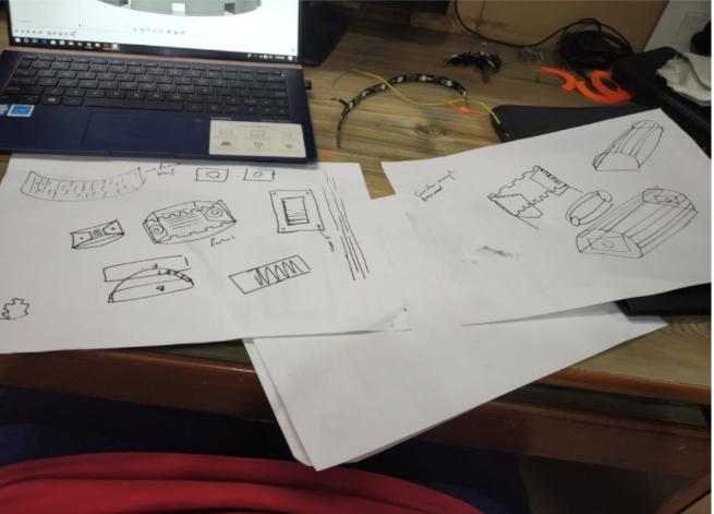
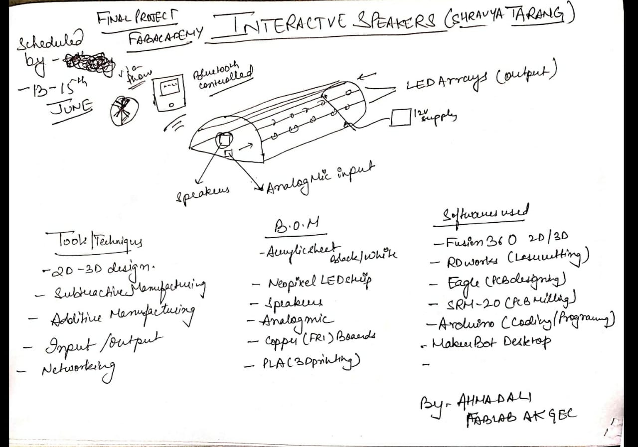
Initial Concept and Sketch
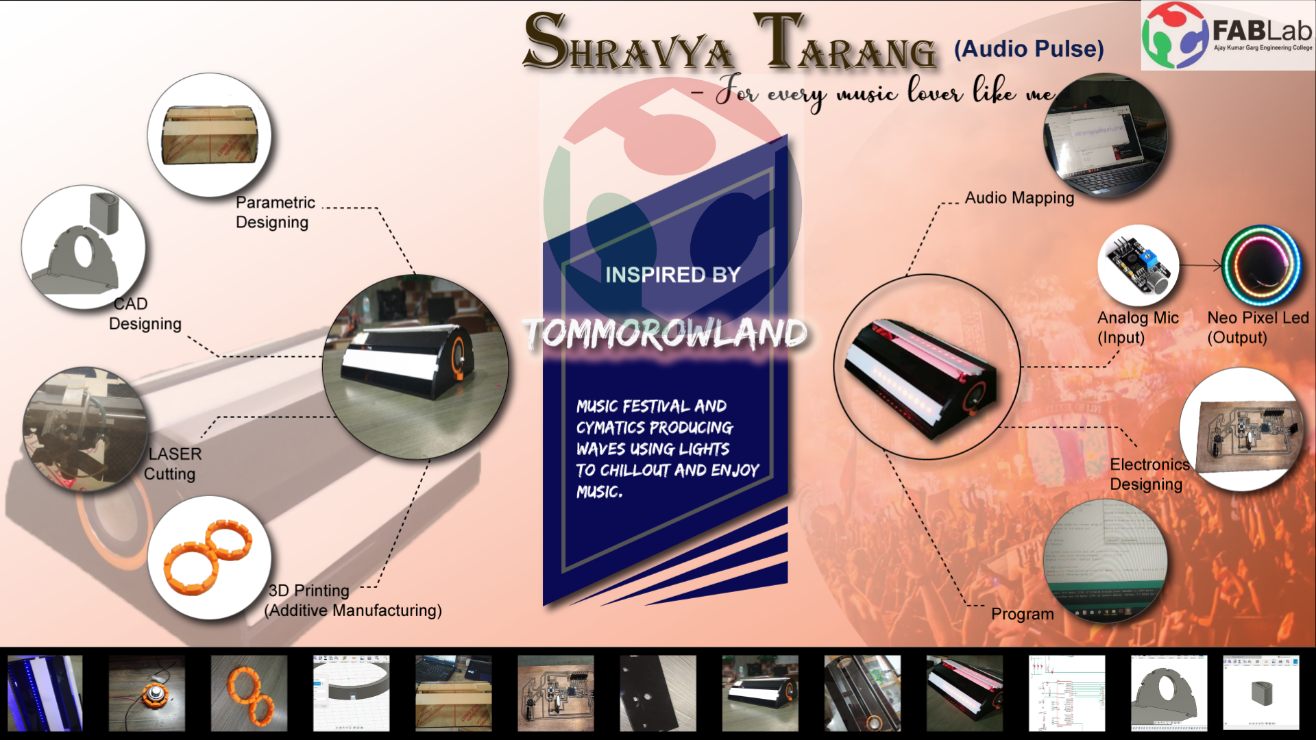
So basically I wanted to make a sound reactive speakers. mapped with the amplitude of the sound waves it will receive via speakers.
I always wanted to have a customize speakers at my room to and wanted to make it cost efficient and attractive too.
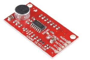
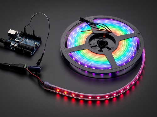
For the input of the project I used analog mic or moreover a sound detector module, through which the sound will get detected from the speaker and according to the return value, the pattern of LED will be mapped.
And the following Adafruit Neopixel LED will be used as the output device which shall be connected to the mic and programmed in such a way that the LED responds to the recorded sound of the mic.
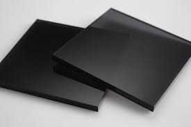
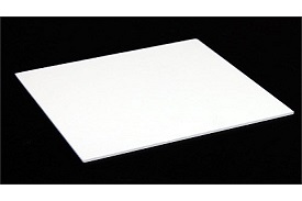
The 5mm black and white Acrylic will be used to produce the outer structure of the lamp. and the enclosure for all the wire management.
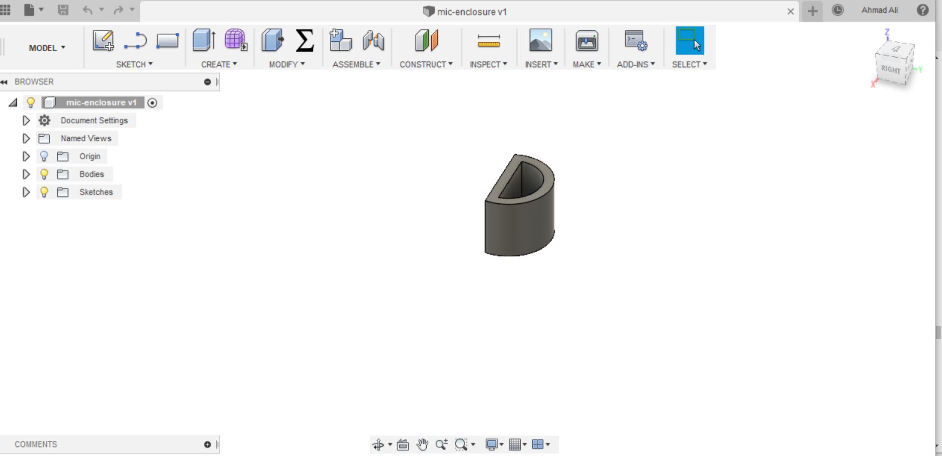
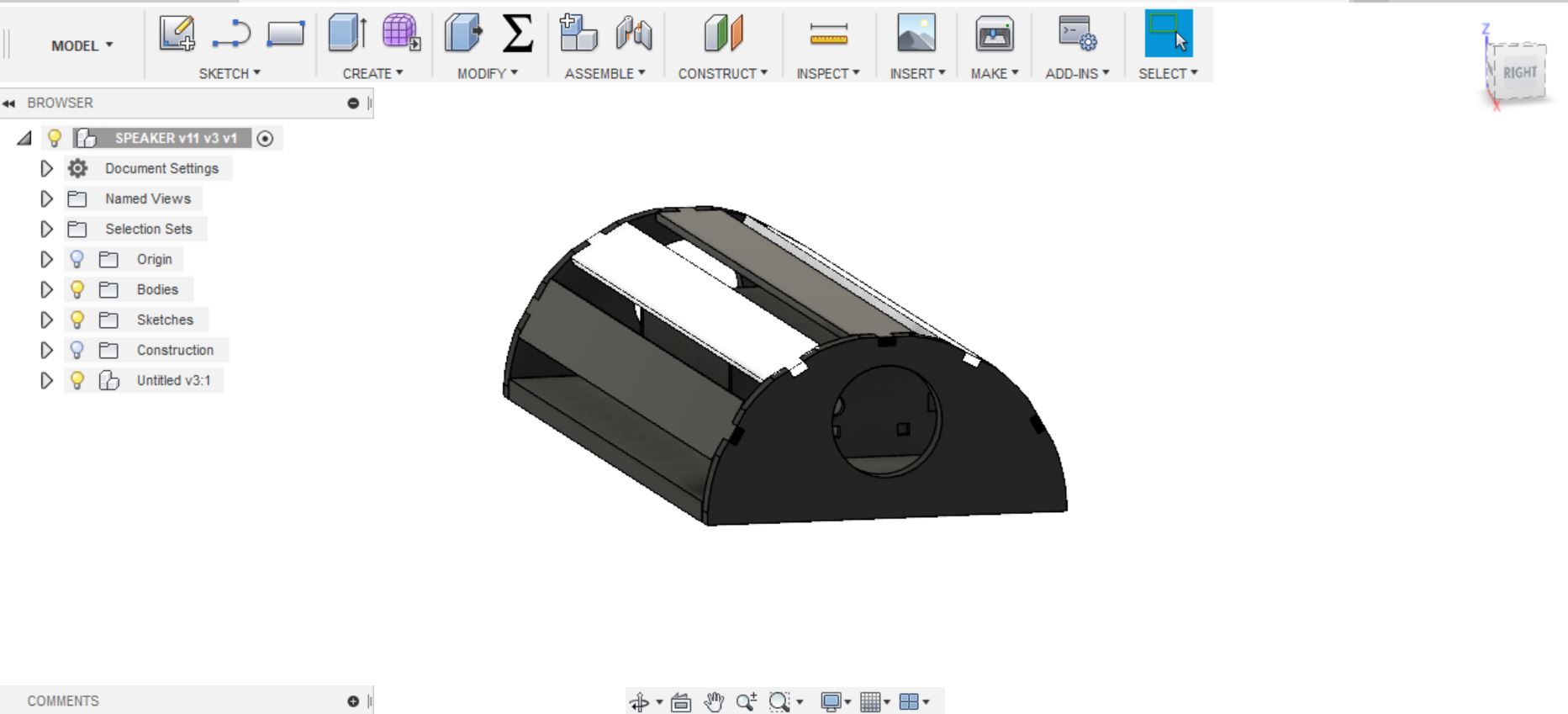
The Design
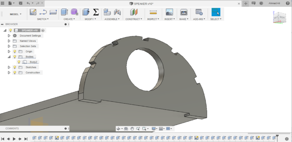
For the Design I used fusion 360 which i've been using new for past few weeks for the assignments.
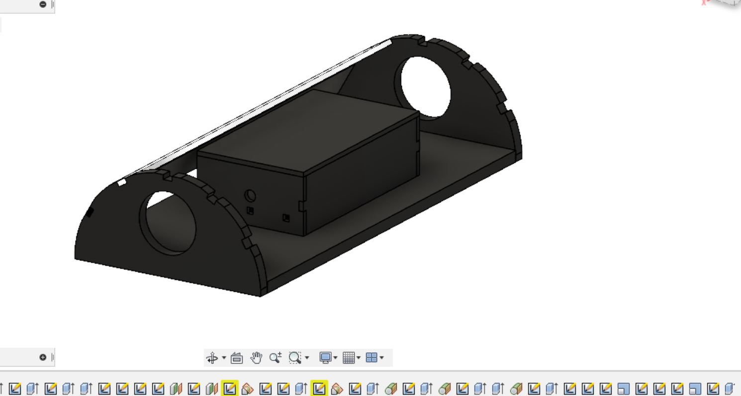
Thinking for the wire management I made a new press fit enclosure inside to put all the circuits and wires.
The slots are deliberately given to add the connector pins.
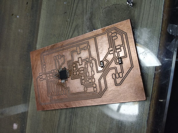
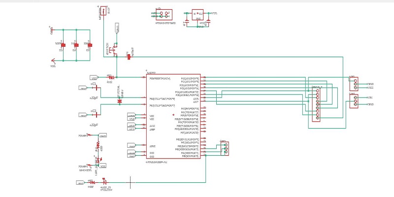
For the purpose I redesigned satshakit and used the Analog pin as the input of th mic and pin number 17 as the output of the the neopixel LED.
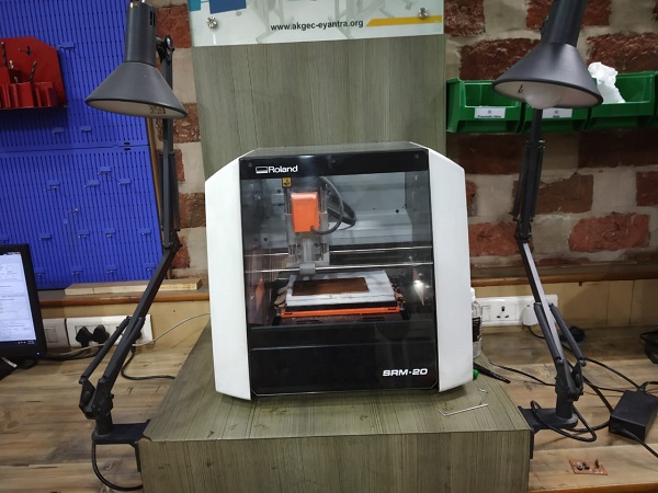
Using fabmodules to generate toolpath.
Make sure to invert the image for generating cut toolpath
SRM in action
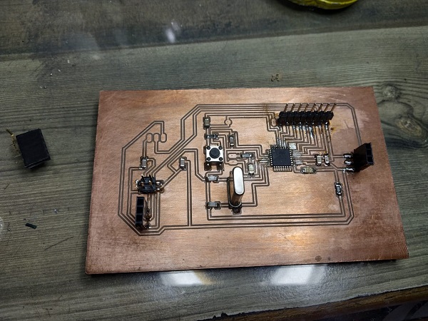
Soldering of Components
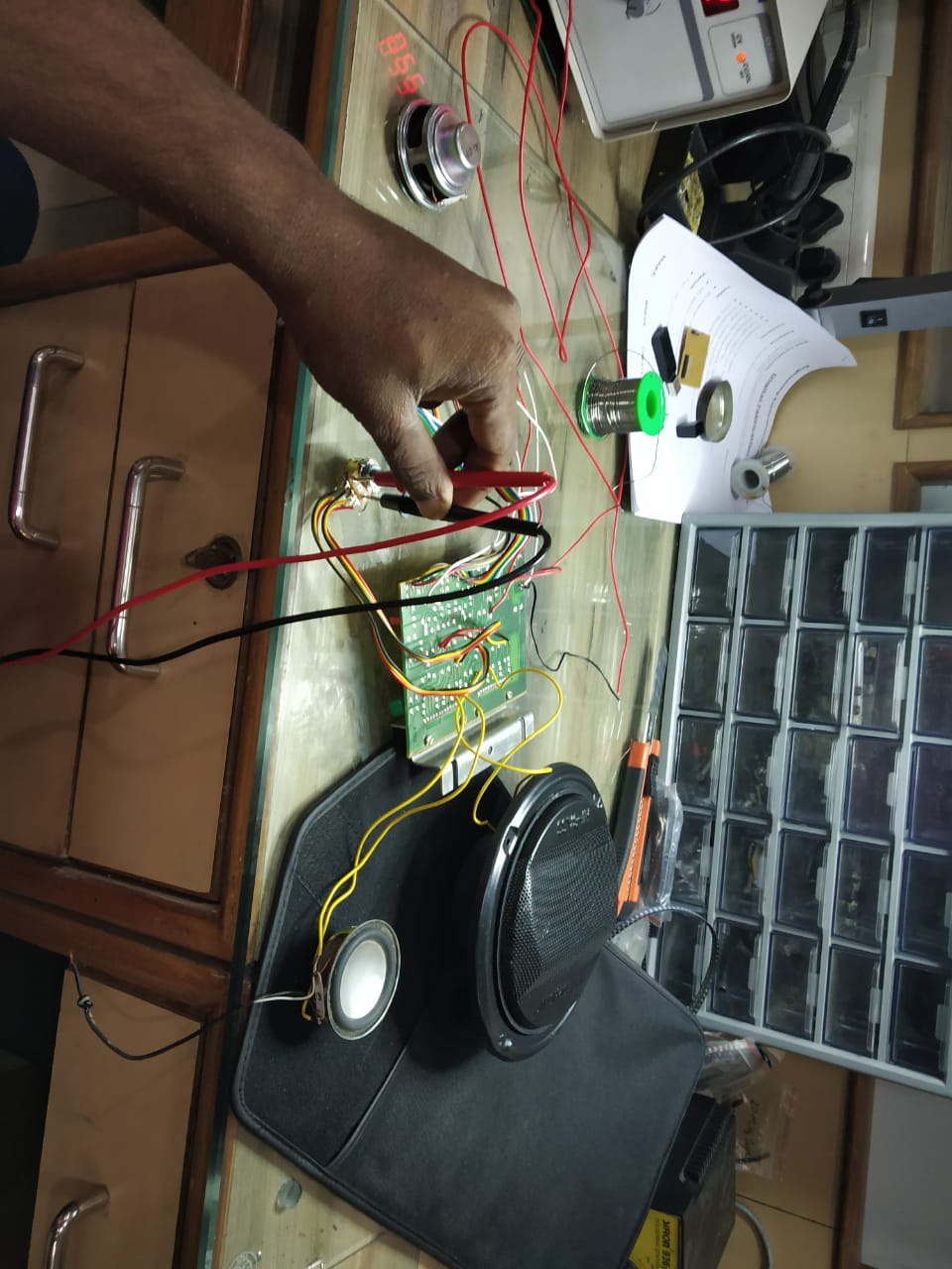
Testing of the Speakers
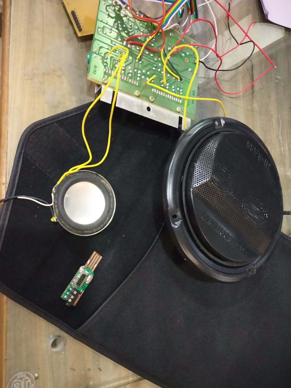
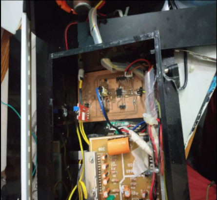
For the speaker and bluetooth connectivity I used a comecial LA 4440 audio driver circuit.
For bluetooth connectivity I used a car Audio Receiver. Dismantle it and used it as the reeiver to the driver circuit that makes the output i.e sound.
I'm using a commercial board beacause after so much reading about amplifier circuits like CLASS A, B, C and AB types I kept it for the next spiral for the project, and limited the scope for this cycle.
For understanding about the classes of amplifier their working and types I referred this article
As following Neil's Spiral Development formula I wanted to build the first module for the project i.e the sound control part and for the next cycle of this project I'll making the amplifier IC and may be working on the wifi connectivity for the project.
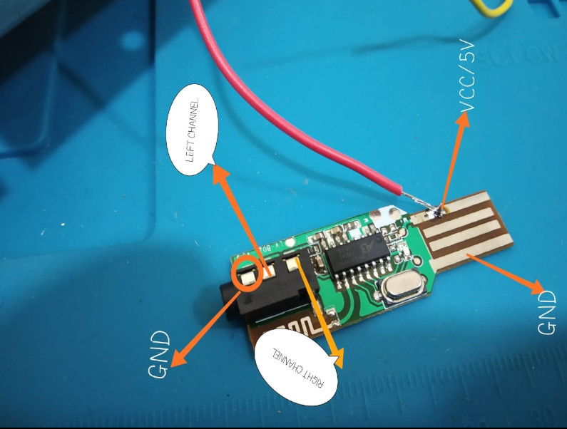
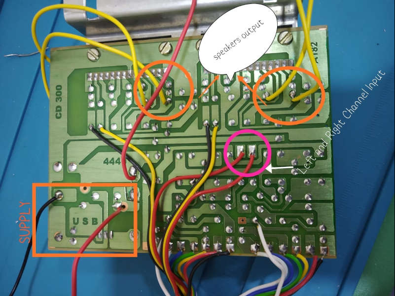
For making the speakers work with bluetooth receiever was simple I just figured out the circuit of the amplifier IC and took the audio bluetooth receiver opened it and reverse engineered the circuit-
For the speakers
I did not touch any potintiometer wiring but just set them to ample amount because I wanted to control the sound by the phone
There were basically two channel input and two corresponding channel output
A 12V supply to power on the amplifier IC and a 7805 regulated 5V output from the board
(which i used to power up the bluetooth module)
For the bluetooth module-
There was VCC and ground rails obviously to power up the module
At front side of AUX input there were the channel inputs for the left and right channels.
Testing on the speakers-
Sorry for the audio Quality
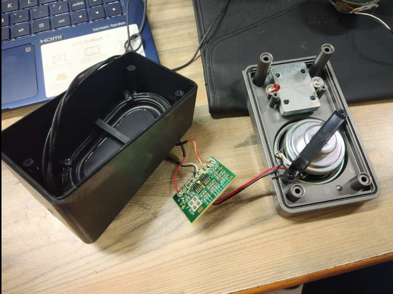
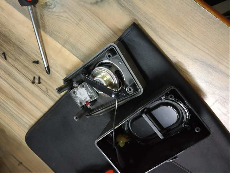
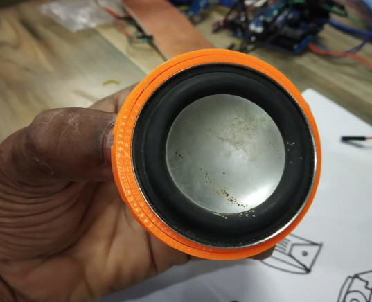
Since I didnot like the audio output of those big bulky speakers I decided to take out one of my friend's old speakers which were discarde by him, I thought to make use of them-
The small ones were small in size but the audio quality was much better and also while designing I wanted small speakers in the enclosure so instead of buying I used the old one's however I've mentioned the cost of them in my BOM.
Testing Of the NeoPixel LED's
For the Neopixel LED's I've already tested them In my output weeks Assignment, you can visit my Output week's assignment from this link.
I used an analog sound module to map the led patterns for the basics I used simple clap to change color codes
which are open source to test the mic and the leds .
Here I noticed when I put the sound sensor just near the periphery of my Laptop speakers and increased it's sensitivity the readings of the output were much better so that it can be mappded.
I got a long range from 29(lowest) to 1024(highest) and also many middle values from few hundreds other wise if th distance was just increased the mapping was almost next to digital like fluctuating between 29 to directly 1024.
There I realized that in the speaker design the placement of mic has to be somewhere near the speakers such that the disatnce between them is minimum.
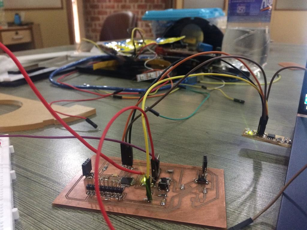
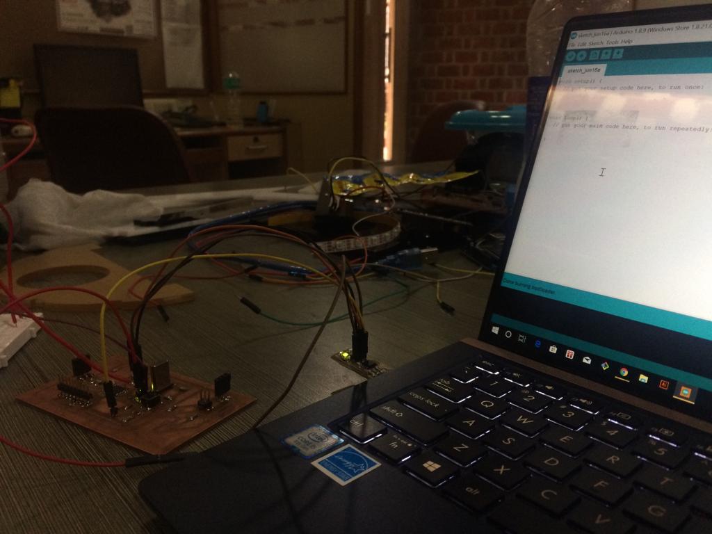
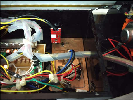
Testing of the final Circuit-
Basically in the circuit I used the input as anlog mic and output the neopixel LED's.
After trying many sound modules I found that the values were not very accurate readings, I figured out that the values of the sensor output were distant dependant so I place the mic just infront of the speakers so that the mapping of LED can be a bit more appealing.
I redesigned Satshakit for the same and give one pin ADC1 as input and 17 as output.
For powering up the circuit i give it via dc jack to the amp board and the 5V output from it used to power the fabduino board I made.
The final Test
Placement of mic-
For the placement of mic I hooked out the mic from te sensor module designed a part in fusion to attach it to infront of thr speakers and 3D printed the model.
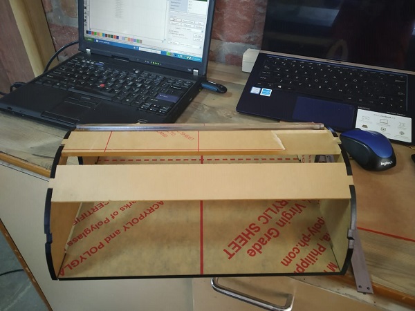
Laser Cutting
For Laser cutting I used 5mm thick acrylic black and white sheet.
The parameters i used to cut the acrylic was-
Power-90-95%Speed-20mm/s
3D printing
For 3D printing I used tough PLA material and slice using makerBot Desktop
The instruction are given in Week 6 Assignment
I printed it using 10% infill with no supports and Rafts on. The rest were the default settings used.
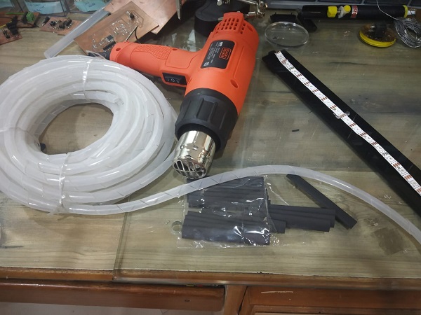
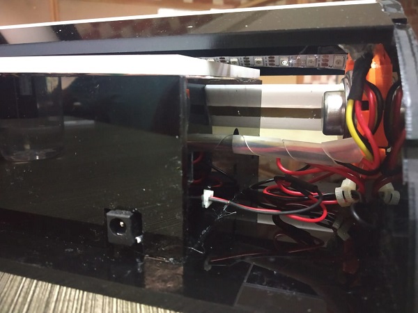
System Integration and wire Management
This was one of the main feature that Neil focussed on as the wires coming out can be fragile and good system needs a good system integartion and it should be robust a bit so that it does not wear tear off in one or two use or in carrying.
For this I got some spiral springs to which I tied all the speaker wires and the enclosure that I laser cut I gave the slots onthe sides acuurately to the size of my coonectors so that it can just fit in and all the messy wiring issues can be improved. I added some masking tape on the IC's just to be sure that there is no chance of Short circuit.
Used some plastic springs and heat Shrings and Tie knots to clean up the wiring
Cleanup Phase-1
Cleanup Phase-2
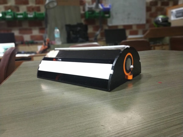
Enclosing Things-Final Finish
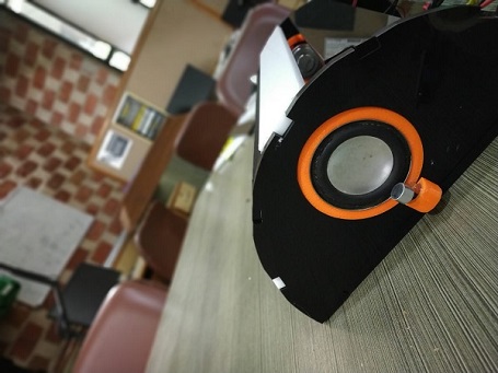
The final Finish Look
The Code
                                                            //The project is done and edited By Ahmad Ali FabLab AKGEC

                                                              #include < Adafruit_NeoPixel.h>
                                                              #ifdef __AVR__
                                                               #include < avr/power.h> // Required for 16 MHz Adafruit Trinket
                                                              #endif
                                                              #include < SoftwareSerial.h>
                                                              SoftwareSerial mySerial(18, 19); // RX, TX
                                                              const int mic= A1;
                                                              const int ledPin=17;
                                                              int mmax=700;
                                                              int mmin=40;
                                                              int leds=10;
                                                              int i=0;
                                                              int val=0;

                                                              //define NeoPixel Pin and Number of LEDs
                                                              #define PIN 17
                                                              #define NUM_LEDS 18
                                                              int sample;
                                                              const int threshold= 31;
                                                              //create a NeoPixel strip
                                                              Adafruit_NeoPixel strip = Adafruit_NeoPixel(NUM_LEDS, PIN, NEO_GRB + NEO_KHZ800);


                                                              void setup() {
                                                                // start the strip and blank it out
                                                                strip.begin();
                                                                pinMode(ledPin,OUTPUT);
                                                                Serial.begin(9600);
                                                                mySerial.begin(9600);
                                                                strip.show();
                                                              }

                                                              void loop()
                                                              {
                                                                val = analogRead(mic);
                                                                //  val = random(mmin,mmax);
                                                                  leds = map(val,mmin,mmax,1,18);
                                                                //  strip.setPixelColor(leds,255,0,0);
                                                                 // strip.show();
                                                               mySerial.println(val);

                                                                for(int i=0;i< leds;i++)
                                                                {
                                                                strip.setPixelColor(i,255,0,0);
                                                                strip.show();
                                                                }
                                                                  delay(50);
                                                                  for(int i=leds;i<19;i++)
                                                                  {
                                                                    strip.setPixelColor(i,0,0,0);
                                                                    strip.show();
                                                                  }

                                                                delay(30);

                                                              }
Experience
The experience creating the final project was too hectic and and amazing at the same time-
I learned a lot of things collectively, working with values of the mic and mapping it with thw LED was one of the irksome task,
It took a lot time to discover that the values were actually distant dependant so I redisgine somrting to make it work.
The under standing of the LASER and 3D Printing in the earlier weeks led to make the design on a bit easy side for me.
The overall weeks learning was reflected in the final project and I'm very happy about it.
Conclusion
Creating a final project in such short span of time was not easy. As weekly assignments are just focused on one task or process, the final project needed task of several processes to be done at the same time. It was not easy to imagine all the functions of the project and then design various processes, such as form, electronics etc. On the whole it was a great experience and it makes one really appreciate the amount of time people have put into even small products, and when it comes to bigger product, several teams or departments, working in unison to create one complete product. The process I have learned in FabAcademy is something that I can utilize in various fields, especially foe my own self as I love making custom stuffs for personal usage.
This journey would not have been possible without the support of Fab Academy, and the people associated with FABLAB AKGEC.
I would like to offer my special thanks to my mentor Rahul Gautam (Ninja Hattori) and Darshan Shah(Chill Out Manager) for their help and
extensive support.
My grateful thanks are also extended to all my colleagues bcause of them I got to learn some really new things not just on the aspect of learning Digital Fabrication but also Value of life and social relations.
Whether it be getting deep Knowledge of the machine and process from Ashish Sir, or quick prototyping Expert hands on from Narendra Bhaiya Some life reflecting sessions with Rajat sir or learning from Jay Sir everyone added to the beauty of the journey.
I would like to extend my special thanks to Battu aka Amitoj an intern at KUKA Akgec who at the worst times helped me a lot in understanding and making things work when I panicked over electronics or silly issues.
Blessings of all my loved ones and friends all across the globe to make this possible for a noobie like me.
Apart from skills fabacademy has given me a lot of things over the past 19 weeks.
And Yes as Neil quotes 'The Journey has Just Started' hoping to build some crazy stuffs in future along with all of you.
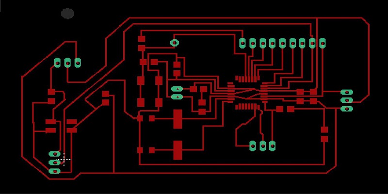

 Make sure to invert the image for generating cut toolpath