Exercise 12. Output Devices
After the lesson about Output Devices, on Wednesday 11th April, the assignment for this week was to:
		INDIVIDUAL ASSIGNMENT:
			_ add an output device to a microcontroller board you've designed,
			and program it to do something

		GROUP ASSIGNMENT:
			_ measure the power consumption of an output device
PREVIOUS CONSIDERATIONS
_ Elements I have selected to this individual assignment are not directly connected to my FINAL PROJECT, but useful to undestand how we can work with output Devices directly linked to inputs.
		I am going to use a LED (INTO PCB) and a SERVO-Motor (OUTSIDE PCB).
		In my final project I will have some Outside Electro-valves,
		and maybe in the future some servo too, which are going to allow me taking care of my plants.
		This exercise helps me undestanding, with an analog actuator (servo), how it will work.
_ I am going to fix first PCB I have done in week 11 assignment , it has 2 considerable errors in board paths.
_ Then, I am going to machine fixed PCB, program it to these Output Devices, and test it.
SERVO MOTOR

There are lots of servo motors available in the market and each one has its own speciality and applications. I has selected TOWER PRO SERVO MOTOR SG-90, enough for this assignment.
Its specifications are:
		- Operating Voltage is +5V typically
		- Torque: 2.5kg/cm
		- Operating speed is 0.1s/60°
		- Gear Type: Plastic
		- Rotation : 0°-180°
		- Weight of motor : 9gm
And I have to take in account its cabes (see them in the image above too) to the board:
		1_ Brown; Ground wire connected to the ground of system.
		2_ Red; Powers the motor typically +5V is used.
		3_ Orange; PWM signal is given in through this wire to drive the motor.
LED
I will add a LEDFAB1206, one green, with different signals (code) depending on the input received.
INDIVIDUAL ASSIGNMENT
1_First step: Fix failed PCB design.
For this, I have taken exercise 11 PCB and I have reconnected each component which failed.
2_Then, when I have it, I will program and test it with all Input and Outpt devices.
1_FIXING AND REMAKING PCB
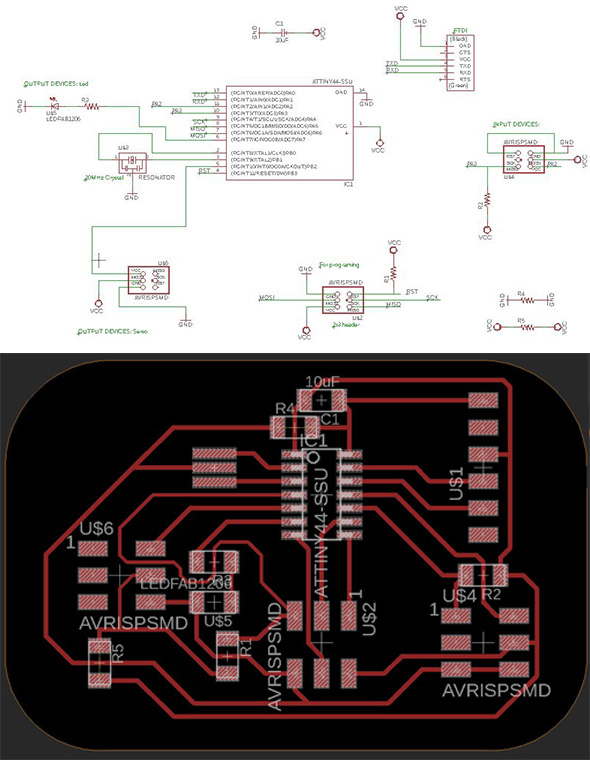
EAGLE
I opened exercise 11 PCB Eagle software project, and I fixed both errors I found in exercise 11.
		Errors fixed:
				_ Connection between Led and its resistor.
				_ Connected RST to its ATtiny44 pin (PB3)
				*As a result, in the 2x3 header inserted for Output Devices, I have only 3 operative pins for one servo.

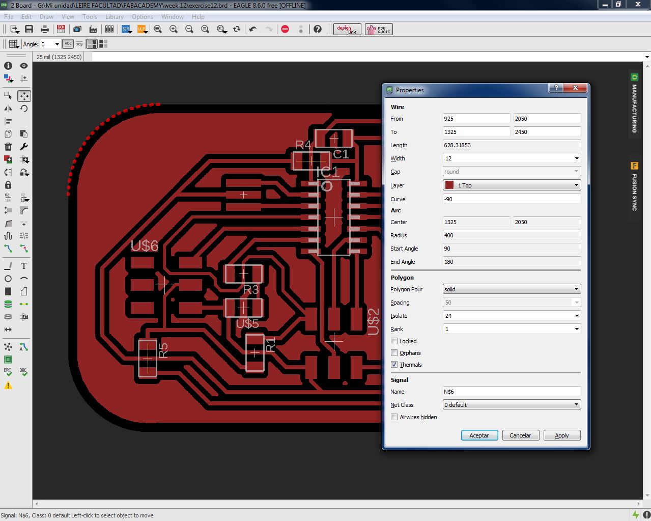
And, this time, I proof to prepare PCB for milling using Eagle. There is an option which can be done:
		> Make a polygon that covers everything.
			* Polygon options can be changed via the parameter toolbar.
			* The POLYGON outline must be a closed contour.
		>> Use the RATSNEST command to calculate and display the surface of the Polygon.
		>>> Right click on the POLYGON outline and click on Properties.
		>>>> It would be on 1 TOP layer + change Isolate value.
			* Isolate defines the isolation distance between the POLYGON and all other copper
			objects that do not carry the same electrical signal or objects in the Dimension.
			* I have set it in 24 after a couple of tries.
And then I passed it (.png) by Photoshop to personalizing, and I export it in .bmp format to go to Dr.Engrave software.

DR ENGRAVE
I opened it in Dr.Engrave software to send it to Roland MX40 we have. Tools used: Engraver V tool and 1mm diameter end-mill (to final board cut). Same procedure as in exercise 07.

I did not realize, but, with Fill value I have insert in the program, there was a point in which the soldering and connection process will be problematic, so I had has to use a precision knive to fix it carefully and it was prepared to solder.

SOLDERING PROCESS

2_PROGRAM AND TEST PCB + OUTPUT DEVICES
My new PCB in going to:
		- Connect Temperature (Input) with Led (Output):
				> When [Tª > 18ºC]; Led will be Switched on always.
				> When [18ºC > Tª > 10ºC]; Led will blink slowly.
				> When [10ºC > Tª]; Led will blink very fast.

		- Connect Humidity (Input) with Servo (Output):
			*Imagine Servo is opening a water gate depending on the humidity, to watering or not plants.
				> When [%H > 70]; Servo will mantain water-gate closed, 0º.
				> When [70 > %H > 40]; Servo will open it a little bit to a drip, 90º.
				> When [40 > %H]; Servo will open entire water-gate, 180º.
PROGRAM PCB
I made the program CODE, but I have had some problems.
		I am making CODE using Arduino, and I used Arduinos SERVO library, but:
			- Arduinos Servo library works with 16 bits, and Tiny44 can work only with 8.
			+ I found SoftwareServo library which works with Arduino and ATtiny micro-controllers,
				I install it and with this everything was OK.
		It wasn't enough space in Tiny44 for my CODE:
			+ I already have included a library of SoftwareSerial (for data messages).
			+ I included SoftwareServo for servo motor.
			- I have had to NOT include SoftwareSerial for this week assignment.
This is the final CODE: (You can apreciate that I did not erase any library and functions, I only convert them in comments to have them available if I need them later)
/* Humidity sensor is measuring the humidity with its values, and we program a formula for doing conversion in percents. Depending on these percents it moves Servo. Same with temperature sensor. Led is blinking depending on its range. We are using ATtiny44 micro-processor. */ //#include//include library which implements software serial port, for comunication #include //include Arduinos Servo library SoftwareServo controlServo; //create an "object" which will control my servo int data = 0; int humidity = 0; int temperature = 0; int pinServo = 8; //PB2 in Tiny int pinLed = 7; //PA7 in Tiny const byte rxpin = 0; //not variable, reception on pin 0 const byte txpin = 1; //not variable, transmision on pin 1. Sends message to PC, communication of micro-controller with PC. //SoftwareSerial mySerial (rxpin, txpin); //set up a new serial object, and say which pin is for reception and which for trasmision void setup() { // put your setup code here, to run once: Here we are configuring speed of the serial port controlServo.attach(pinServo); //mySerial.begin(9600); //bits per second, 9600 is standard speed pinMode(pinLed, OUTPUT); } void loop() { // put your main code here, to run repeatedly: data=analogRead(A2); //humidity sensor read humidity=(int)((data*10)/77); // we need to make a percent, and logical operation would be data*100/773, but the DATA is too big (long number) for this Attiny44 (77000>32000) //mySerial.print("Humidity is:"); //mySerial.print(humidity); //mySerial.println("%"); if ((humidity<70) && (humidity>40)) { //mySerial.println (90); controlServo.write(90); } else { if (humidity<40) { //mySerial.println (180); controlServo.write(180); } else { //mySerial.println (0); controlServo.write(0); } } SoftwareServo::refresh(); //actualizes speeds temperature= map(analogRead(A3), 626,500, 10,22); //mapping Tª range to make conversión to ºC if (temperature<10) { digitalWrite(pinLed, HIGH); delay(100); digitalWrite(pinLed, LOW); delay(100); } else { if ((temperature>10) && (temperature<18)) { digitalWrite(pinLed, HIGH); delay(400); digitalWrite(pinLed, LOW); delay(200); } else { digitalWrite(pinLed, HIGH); } } delay(20); }
Finally I programmed PCB using USBTinyISP we have done in exercise 05: Electronics Production:
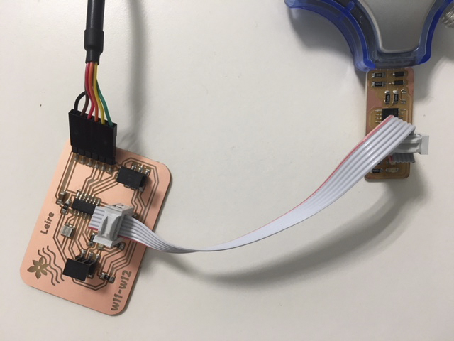
And I connected all components, INPUT and OUTPUT to test them. I have to comment that output devices connection is like you see in the image below only for testing them, they would be completly integrated in the main PCB in the Final Project. This connection mode is only for testing:

OUH YEAH! The video below shows how it is working: Led is switched on due to room Tª=23ºC, and we can see how Servo moves depending on water.
GROUP ASSIGNMENT
For measurement of the power consumption of an output device we have used Javi's new PCB, and specifically the connection to a DC Motor.

The motor is controlled by an A4950 driver. A PWM signal is applied to this driver and in function of Duty cycle more or less power is directed to the motor.
Javi has programmed it with this sequence: 2 seconds switched off, 2 seconds in 20% Duty cycle and 2 seconds in 40% Duty cycle. In this mode we can measure motor power consumption in each of this sequences.
		1- Connect 9V to the board using the Power supply.
		2- Connect the motor to the output of the driver (in PCB)
		3- we can read the measurement of the current and power in the Power supply screen.
			This measurement is about ALL in the PCB, not only motor’s consumption.

		4- With the Oscilloscope we have measured SHUNT resistor signal:
		A voltage signal proportional to the current of the motor.
		The SHUNT resistor is 0’25 Ohm, so we have to divide the voltage with this number.
										[V=RI]
Data we have obtained doing this tests is:
| Duty Cycle | I | P |
|---|---|---|
| 0% | 0,016 A | 0,144 W |
| 20% | 0,176 A | 1,605 W |
| 40% | 0,351 A | 3,216 W |
The consumption of the PCB with motor switched off is about 0,144W, and when motor is running its consumption is added to it.
In the first sequence; Motor is consuming (1,605-0,144)=1,461 Watts, and in the second sequence (3,216-0,144)=3,072 Watts.
DOWNLOADS
_ SoftwareServo library for ARDUINO