Exercise 09. Embedded programming
After the lesson about Embedded Programming, on Wednesday 14 March, the assignment for this week was to:
		INDIVIDUAL ASSIGNMENT:
						_ read a micro-controller data sheet
						_ program your board to do something
							*with as many different programming languages
							and programming environments as possible
		GROUP ASSIGNMENT:
						_ experiment with other architectures
PREVIOUS CONSIDERATIONS
This week assignment is directly linked to Electronics Design exercise. We re-drawed a Echo-Hello-World board, we added a led and a button, and we programmed it using some predetermined files.
In Electronics Design week I tented to change programming of echo Hello-world using Arduino and C, and this week I would try to improve my programming skills doing something new.
I am going to program my board to:
			_ Send a visual SOS signal in Morse code: Through the Led.
			_ Send a text SOS message to the PC in which it is connected.

Then, for Group assignment, Javi and me would like to prepare a simple programming for different architectures, and see what is the difference between them using an oscilloscope.
INDIVIDUAL ASSIGNMENT
1_READ A MICRO-CONTROLLER DATA SHEET
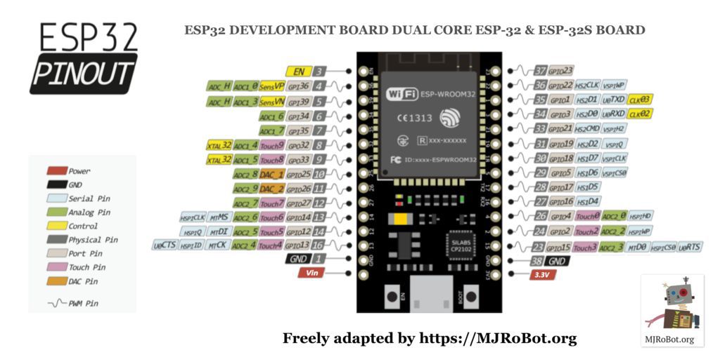
I have downloaded 8-bit AVR Microcontroller with 2/4/8K Bytes In-System Programmable Flashmanual for ATtiny 24, 44 and 84.
From this Data-sheet I have understood better how ATtiny44 pins are configured, what can I connect to each type of pin, and that there is a lot of technical information for my next exercises where I am going to use this Micro-controller.
And, speaking with Szilard and Javi, we realized that for my project I will need a stronger micro-processor, due to project complexity. So I have downloaded ATmega328/P data sheet. I think it will be the suitable micro-controller I will use.
It is a long read and I have to pay close attention, so I'll read it part by part, to be prepared for the day of making my own Final Project PCB with it.
2_PROGRAM MY BOARD TO DO SOMETHING
As I am more familiar with Arduino programming language, so I began with it. The Arduino language is merely a set of C/C++ functions that can be called from own code. Each sketch undergoes minor changes (e.g. automatic generation of function prototypes) and then is passed directly to a C/C++ compiler (avr-g++). All standard C and C++ constructs supported by avr-g++ should work in Arduino. So it is an easy way to begin playing with programming for people like me. :)
*Here ATtiny Using Arduino FabAcademy tutorial for this week.
Then, and with help of my mate Javi (in other way it will be impossible), I made the same program using C, and in this case using ATmel Studio. Studio 7 is the integrated development platform (IDP) for developing and debugging all AVR and SAM micro-controller applications. It gives you a seamless and easy-to-use environment to write, build and debug your applications written in C/C++ or assembly code. In this case, I have to be honest, it would have been impossible without Javi's help. :S
*Here ATtiny Using C FabAcademy tutorial for this week.
(I copy step by step the programming process of each programming language I have done in Electronics Design exercise two week ago.)
Programming it with ARDUINO
			1_ Download Arduino software from the site.
			2_ In Internet we can find a lot of tutorials like this.
			In this web-page we can find a link to "install" ATtiny micro-controllers in Arduino libraries in Preferences.
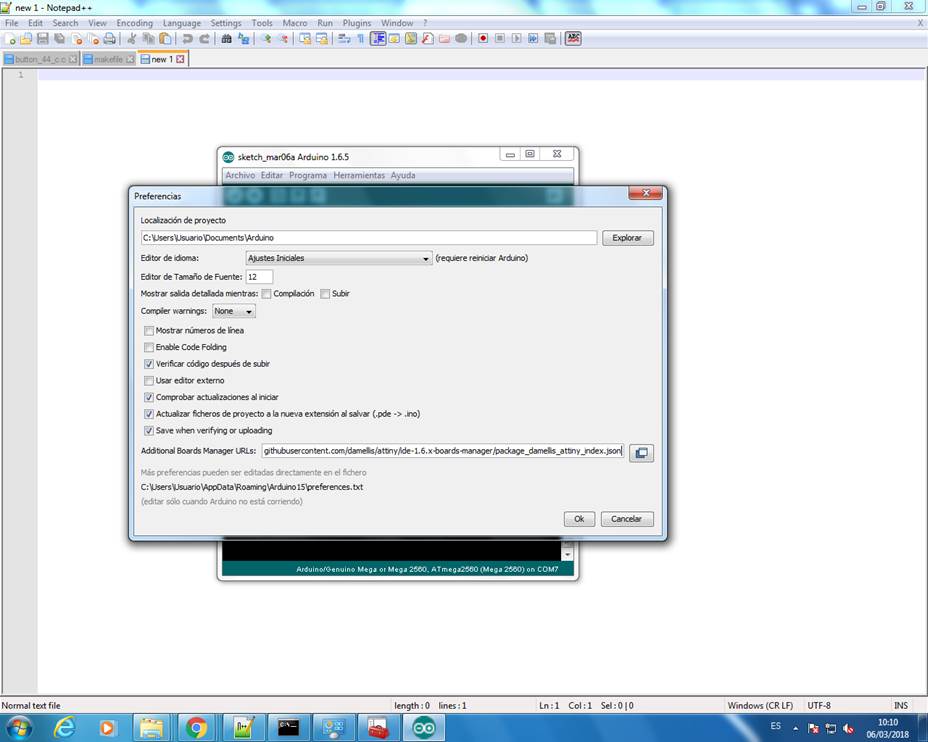
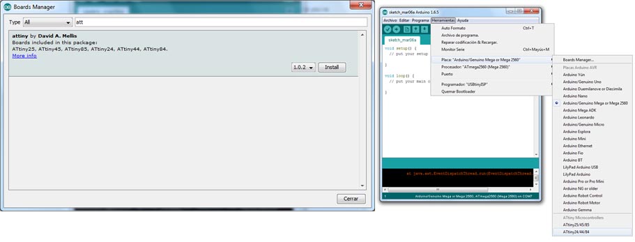
			3_ Select, in Boards Manager attiny and install it.
			Then, in Tools (Herramientas) select ATtiny44 as processor and USBtinyIPS as programmer.
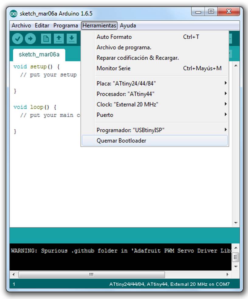
			4_ Tools/Burn Bootloader (Quemar Bootloader)
			to say to USBtinyISP and PCB to be programmed with Arduino.
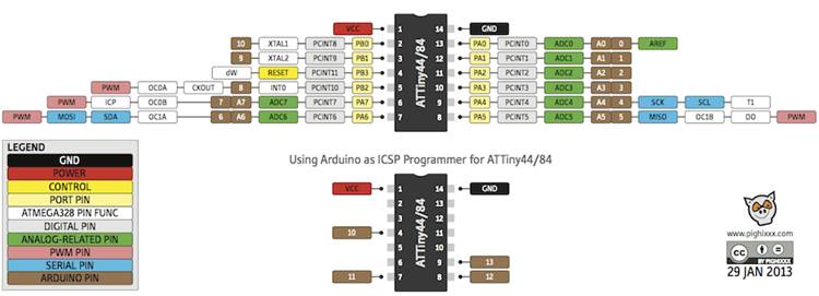
5_ See ATtiny scheme below to know each connection pin number in Arduino language.
My scheme says that my INPUT (Button) is pin 2 and OUTPUT (Led) is pin 3.
6_ Write the program taking in account these pins:

!! First time I made a mistake, I have write to have Led switched on everytime, and switch off it when Button was pushed, but I change it and it works well!
You can find my Arduino program here.
7_ Send program to board withbutton.
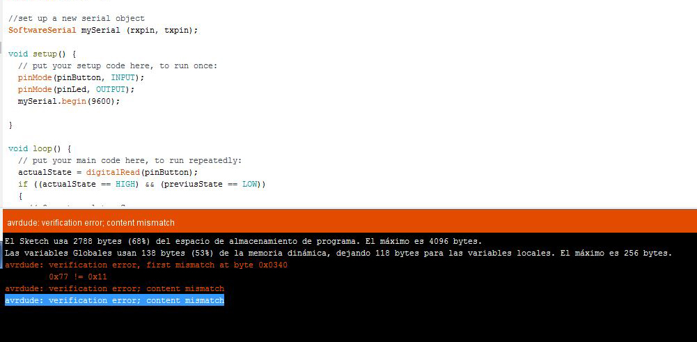
ERROR! I don't know why, cause all parameters and settings in Arduino were well, and two weeks ago it worked, but in my computer was impossible to program it. There was a mismatch! See the image below.
At the end we connect it to Javi computer, and it worked.
8_ Test it with Arduino pressingbutton.
Push the button in the board, and it says SOS after in PCB the Led switches on and off in Morse code, yeah!
Programming it with C
The key in this option for programming is that it is complex and it needs knowledge about micro-processors inside architecture (cells, 0 and 1 positioning, OR and AND functions, DDRA, DINA, ecc.) and it is not easy to everybody :S
In this case I select ATmel Studio to test another different environment. As I said before, helped by my mate Javi (in other way it will be impossible).
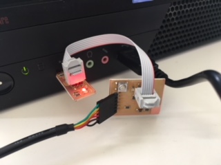
1_ Connect with each other PCB and USBTiny programmer, and then both to computer USB ports:
2_ Open Atmel studio software.

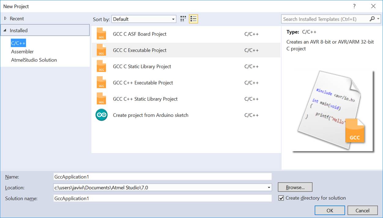
3_ Open New Project, it would be GCC executable Project, to work with C lenguage.
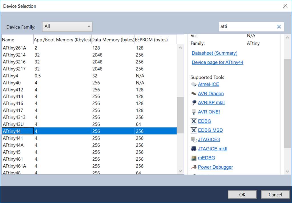
4_ Device selection >> Select ATtiny44, micro-controller we I have in my PCB.
It would create the main body of the program.
5_ Write program to send SOS message (using text and led) when button is pressed.
Consulting exercise 07 C and Arduino programming, I had written my new C program to say SOS pressing the button. Javi has helped me, to understand changes between Arduino and C languages.

/* * buttonledSOS.c * * Created: 19/03/2018 17:00:43 * Author : leire.bereziartua */ #include#include #include #define output(directions,pin) (directions |= pin) // set port direction for output #define input(directions,pin) (directions &= (~pin)) // set port direction for input #define set(port,pin) (port |= pin) // set port pin #define clear(port,pin) (port &= (~pin)) // clear port pin #define pin_test(pins,pin) (pins & pin) // test for port pin #define bit_test(byte,bit) (byte & (1 << bit)) // test for bit set #define bit_delay_time 8.5 // bit delay for 115200 with overhead #define bit_delay() _delay_us(bit_delay_time) // RS232 bit delay #define half_bit_delay() _delay_us(bit_delay_time/2) // RS232 half bit delay #define char_delay() _delay_ms(10) // char delay #define serial_port PORTA #define serial_direction DDRA #define serial_pins PINA #define serial_pin_in (1 << PA0) #define serial_pin_out (1 << PA1) #define input_port PORTA // The button is on port A #define input_direction DDRA // DDRA defines input/output for port A #define input_pin (1 << PA2) // The button is on pin 5 of port A #define input_pins PINA // PINA is the register that is read to detect input high or low. #define output_port PORTA // port A will be used for the LED #define output_direction DDRA #define output_pin (1 << PA3) //output pin of Led #define max_buffer 25 void put_char(volatile unsigned char *port, unsigned char pin, char txchar) { // // send each character in txchar on port pin // assumes line driver (inverts bits) // // start bit // clear(*port,pin); bit_delay(); // // unrolled loop to write data bits // if bit_test(txchar,0) set(*port,pin); else clear(*port,pin); bit_delay(); if bit_test(txchar,1) set(*port,pin); else clear(*port,pin); bit_delay(); if bit_test(txchar,2) set(*port,pin); else clear(*port,pin); bit_delay(); if bit_test(txchar,3) set(*port,pin); else clear(*port,pin); bit_delay(); if bit_test(txchar,4) set(*port,pin); else clear(*port,pin); bit_delay(); if bit_test(txchar,5) set(*port,pin); else clear(*port,pin); bit_delay(); if bit_test(txchar,6) set(*port,pin); else clear(*port,pin); bit_delay(); if bit_test(txchar,7) set(*port,pin); else clear(*port,pin); bit_delay(); // // stop bit // set(*port,pin); bit_delay(); // // char delay // bit_delay(); } void put_string(volatile unsigned char *port, unsigned char pin, char *str) { // // print a null-terminated string // static int index; index = 0; do { put_char(port, pin, str[index]); ++index; } while (str[index] != 0); } int main(void) { // set clock divider to /1, speed // CLKPR = (1 << CLKPCE); CLKPR = (0 << CLKPS3) | (0 << CLKPS2) | (0 << CLKPS1) | (0 << CLKPS0); // // initialize output pins // set(serial_port, serial_pin_out); output(serial_direction, serial_pin_out); //output SOS output(output_direction, output_pin); //output led // // main loop // int previusState = 0; // variable, for store past value of Button state int actualState; // variable, for store actual value of Button state while (1) { //put_string(&serial_port, serial_pin_out, "SOS\n"); actualState=pin_test(input_pins,input_pin); if (actualState&&!previusState){ for(int i=0;i<3;i++){ set(output_direction, output_pin); _delay_us(150000); clear(output_direction, output_pin); _delay_us(100000); } put_string(&serial_port, serial_pin_out, "SOS\n"); } previusState=actualState; _delay_us(20000); } }
First of all, I have programmed only actions to send text SOS message to the computer and the first S letter Led Morse code, to see if it is working well.
6_ Configure the USBtinyISP in external tools. For doing it I will find this tutorial and I downloaded AVRdude needed from here.

7_ Select USBtiny as tool for programming.

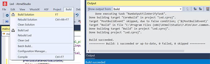
8_ Build/Build solution, and see that it is succeeded.
			9_ Open Arduino software and with PCB connected to the computer,
			press button to see its performance.

SOS text message to
Another thing it was wrong was the speed of the processor, F_CPU, that I have configured doing next step:
		Project -> Toolchain -> AVR/GNU C Compiler -> Symbols
		then add F_CPU=8000000 (or whatever) >> 20000000 in my case due to 20MHz Chrystal.
Finally I found the error, I wrote it wrong :S >> I wrote output_direction where I had to write output_port. See image and final code below:

/* * buttonledSOS.c * * Created: 19/03/2018 17:00:43 * Author : leire.bereziartua */ #include#include #include #define output(directions,pin) (directions |= pin) // set port direction for output #define input(directions,pin) (directions &= (~pin)) // set port direction for input #define set(port,pin) (port |= pin) // set port pin #define clear(port,pin) (port &= (~pin)) // clear port pin #define pin_test(pins,pin) (pins & pin) // test for port pin #define bit_test(byte,bit) (byte & (1 << bit)) // test for bit set #define bit_delay_time 8.5 // bit delay for 115200 with overhead #define bit_delay() _delay_us(bit_delay_time) // RS232 bit delay #define half_bit_delay() _delay_us(bit_delay_time/2) // RS232 half bit delay #define char_delay() _delay_ms(10) // char delay #define serial_port PORTA #define serial_direction DDRA #define serial_pins PINA #define serial_pin_in (1 << PA0) #define serial_pin_out (1 << PA1) #define input_port PORTA // The button is on port A #define input_direction DDRA // DDRA defines input/output for port A #define input_pin (1 << PA2) // The button is on pin 5 of port A #define input_pins PINA // PINA is the register that is read to detect input high or low. #define output_port PORTA // port A will be used for the LED #define output_direction DDRA #define output_pin (1 << PA3) //output pin of Led #define max_buffer 25 void put_char(volatile unsigned char *port, unsigned char pin, char txchar) { // // send each character in txchar on port pin // assumes line driver (inverts bits) // // start bit // clear(*port,pin); bit_delay(); // // unrolled loop to write data bits // if bit_test(txchar,0) set(*port,pin); else clear(*port,pin); bit_delay(); if bit_test(txchar,1) set(*port,pin); else clear(*port,pin); bit_delay(); if bit_test(txchar,2) set(*port,pin); else clear(*port,pin); bit_delay(); if bit_test(txchar,3) set(*port,pin); else clear(*port,pin); bit_delay(); if bit_test(txchar,4) set(*port,pin); else clear(*port,pin); bit_delay(); if bit_test(txchar,5) set(*port,pin); else clear(*port,pin); bit_delay(); if bit_test(txchar,6) set(*port,pin); else clear(*port,pin); bit_delay(); if bit_test(txchar,7) set(*port,pin); else clear(*port,pin); bit_delay(); // // stop bit // set(*port,pin); bit_delay(); // // char delay // bit_delay(); } void put_string(volatile unsigned char *port, unsigned char pin, char *str) { // // print a null-terminated string // static int index; index = 0; do { put_char(port, pin, str[index]); ++index; } while (str[index] != 0); } int main(void) { // set clock divider to /1, speed // CLKPR = (1 << CLKPCE); CLKPR = (0 << CLKPS3) | (0 << CLKPS2) | (0 << CLKPS1) | (0 << CLKPS0); // // initialize output pins // set(serial_port, serial_pin_out); output(serial_direction, serial_pin_out); //output SOS output(output_direction, output_pin); //output led // // main loop // int previusState = 0; // variable, for store past value of Button state int actualState; // variable, for store actual value of Button state while (1) { //put_string(&serial_port, serial_pin_out, "SOS\n"); actualState=pin_test(input_pins,input_pin); if (actualState&&!previusState){ for(int i=0;i<3;i++){ set(output_port, output_pin); _delay_us(150000); clear(output_port, output_pin); _delay_us(100000);} for(int i=0;i<3;i++){ set(output_port, output_pin); _delay_us(300000); clear(output_port, output_pin); _delay_us(100000);} for(int i=0;i<3;i++){ set(output_port, output_pin); _delay_us(150000); clear(output_port, output_pin); _delay_us(100000); } put_string(&serial_port, serial_pin_out, "SOS\n"); } previusState=actualState; _delay_us(20000); } }
And it is working now! In the same way it has done with Arduino programming.
GROUP ASSIGNMENT
For the group assignment, we thought that the easier way was to prepare a simple programming for different architectures, and see what is the difference between them using an oscilloscope.
So, this week, my FabAcademy mate, Javi Vicente and me, have compared the performance and development work flows for other architectures.
We have tried STM32 and ESP32.
And then, as we have a Micro Bit board on hand, we played a little bit with it too.
STM32 architecture
The STM32 is a family of micro-controller of the ST Microelectronic company. This type of micro-controller is based on Cortex-M architecture. In particular we have probe the STM32F401RE. This micro-controller have a Cortex-M4 micro-controller. For the test we have used the Nucleo F401RE board. The program is very easy only configure and output pin and tongue it in a loop, so we can measure the change frequency with and oscilloscope.

We have test a basic program in this micro-controllers using different methods:
- 1_Register level configuration.
- 2_Using manufacturer HAL library.
- 3_Using a configuration wizard, STM32CubeMX
- 4_Using Mbed
- 5_Arduino in STM32
1_STM32: Register level configuration
Using register level configuration is the lower configuration method. It is the most complicated one but is in witch you have more control of the micro-controller. You can see the code we used below, and all the project can be downloaded using this link.
		#include "stm32f4xx.h"

		#define RCC_AHB1ENR 	(*(volatile uint32_t *) (0x40023830))

		#define GPIOA_MODER 	(*(volatile uint32_t *) (0x40020000))
		#define GPIOA_OTYPER 	(*(volatile uint32_t *) (0x40020004))
		#define GPIOA_OSPEEDR 	(*(volatile uint32_t *) (0x40020008))
		#define GPIOA_PUPDR 	(*(volatile uint32_t *) (0x4002000C))
		#define GPIOA_IDR 		(*(volatile uint32_t *) (0x40020010))
		#define GPIOA_ODR 		(*(volatile uint32_t *) (0x40020014))
		#define GPIOA_BSRR 		(*(volatile uint32_t *) (0x40020018))

		int main(){

			RCC_AHB1ENR|=0x11U;

			//Salida LED
			GPIOA_MODER&=~(3<<2*5);
			GPIOA_MODER|=1<<2*5;
			GPIOA_OTYPER&=~(1<<5);
			GPIOA_OSPEEDR&=~(3<<2*5);
			GPIOA_OSPEEDR|=1<<2*5;
			GPIOA_PUPDR&=~(3<<2*5);

			while(1){
					GPIOA_ODR^=1<<5;
			}
		}
_ RCC_AHB1ENR >> enable the clock signal to the desired ports. Assigning 0x11 the gobal GPIO and the GPIOA are enabled.
_ GPIOA_MODER >> define the type of the pin, configuring it as output.
_ GPIOA_OSPEEDR >> define speed of the pin.
_ GPIOA_PUPDR >> define port pull-up/pull-down.
_ GPIOA_ODR >> define the output value of the pin.
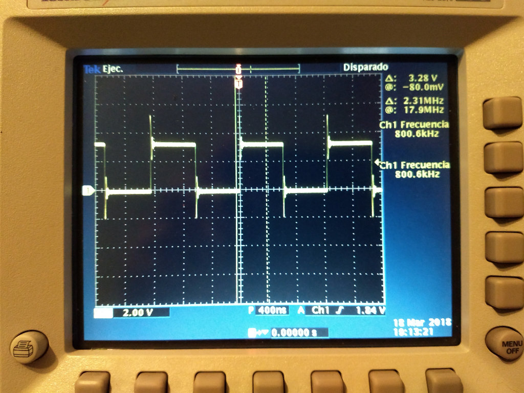
As can be see, in the picture below, a frequency of 800kHz have been reached.
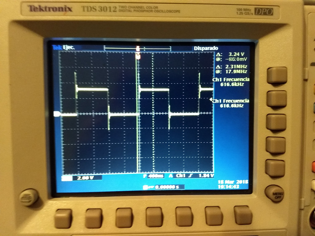
2_STM32: Using manufacturer HAL library
The manufacturer provide us a library called HAL (Hardware Abstraction Layer). This library simplify the configuration of the peripherals of the micro-controller. Files here. You can choose in keil uvision witch libraries are included in your project.

The code using this library is more simple. You can use a data structure to define the configuration of the GPIO and then call a function to configure the GPIO.
			#include "stm32f4xx.h"
			#include "stm32f4xx_hal_gpio.h"
			#include "stm32f4xx_hal_rcc.h"
			#include "stm32f4xx_hal.h"

			GPIO_InitTypeDef GPIO_InitStructure;

			int main(void) {


				__HAL_RCC_GPIOA_CLK_ENABLE();
				GPIO_InitStructure.Pin   = GPIO_PIN_5;
				GPIO_InitStructure.Mode  = GPIO_MODE_OUTPUT_PP;
				GPIO_InitStructure.Pull  = GPIO_NOPULL ;
				GPIO_InitStructure.Speed = GPIO_SPEED_HIGH;
				HAL_GPIO_Init(GPIOA, &GPIO_InitStructure);


				while (1) {
						HAL_GPIO_TogglePin(GPIOA, GPIO_PIN_5);
			   }
			}
As can be seen in the picture below a frequency of 616kHz have been reached, a bit lower than the previous test.
3_Using a configuration wizard, STM32CubeMX
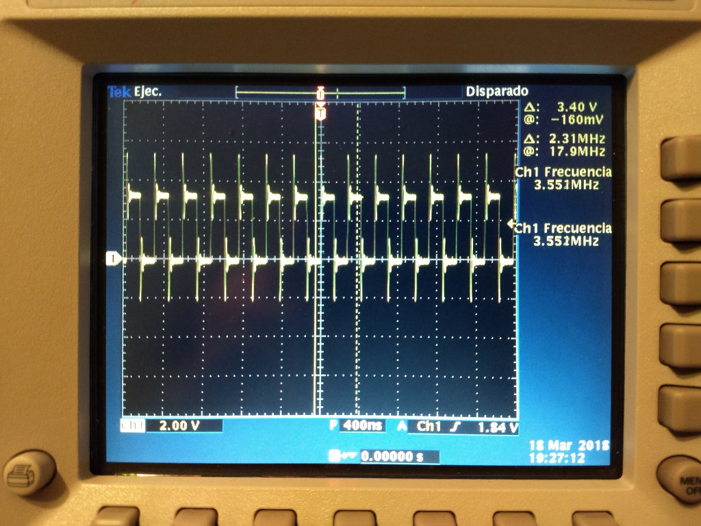
The STM32CubeMX is a graphical tool that allows a very easy configuration of STM32 micro-controllers and the generation of the corresponding initialization C code through a step-by-step process. Using this tool is very easy to configure the correct clock rate.

The STM32CubeMX is a very good tool, it generate the initialization code and you have only to write the user code. The code we used is below this line, and all the project can be downloaded using this link.
		/**
	  ******************************************************************************
	  * @file           : main.c
	  * @brief          : Main program body
	  ******************************************************************************
	  ** This notice applies to any and all portions of this file
	  * that are not between comment pairs USER CODE BEGIN and
	  * USER CODE END. Other portions of this file, whether
	  * inserted by the user or by software development tools
	  * are owned by their respective copyright owners.
	  *
	  * COPYRIGHT(c) 2018 STMicroelectronics
	  *
	  * Redistribution and use in source and binary forms, with or without modification,
	  * are permitted provided that the following conditions are met:
	  *   1. Redistributions of source code must retain the above copyright notice,
	  *      this list of conditions and the following disclaimer.
	  *   2. Redistributions in binary form must reproduce the above copyright notice,
	  *      this list of conditions and the following disclaimer in the documentation
	  *      and/or other materials provided with the distribution.
	  *   3. Neither the name of STMicroelectronics nor the names of its contributors
	  *      may be used to endorse or promote products derived from this software
	  *      without specific prior written permission.
	  *
	  * THIS SOFTWARE IS PROVIDED BY THE COPYRIGHT HOLDERS AND CONTRIBUTORS "AS IS"
	  * AND ANY EXPRESS OR IMPLIED WARRANTIES, INCLUDING, BUT NOT LIMITED TO, THE
	  * IMPLIED WARRANTIES OF MERCHANTABILITY AND FITNESS FOR A PARTICULAR PURPOSE ARE
	  * DISCLAIMED. IN NO EVENT SHALL THE COPYRIGHT HOLDER OR CONTRIBUTORS BE LIABLE
	  * FOR ANY DIRECT, INDIRECT, INCIDENTAL, SPECIAL, EXEMPLARY, OR CONSEQUENTIAL
	  * DAMAGES (INCLUDING, BUT NOT LIMITED TO, PROCUREMENT OF SUBSTITUTE GOODS OR
	  * SERVICES; LOSS OF USE, DATA, OR PROFITS; OR BUSINESS INTERRUPTION) HOWEVER
	  * CAUSED AND ON ANY THEORY OF LIABILITY, WHETHER IN CONTRACT, STRICT LIABILITY,
	  * OR TORT (INCLUDING NEGLIGENCE OR OTHERWISE) ARISING IN ANY WAY OUT OF THE USE
	  * OF THIS SOFTWARE, EVEN IF ADVISED OF THE POSSIBILITY OF SUCH DAMAGE.
	  *
	  ******************************************************************************
	  */
	/* Includes ------------------------------------------------------------------*/
	#include "main.h"
	#include "stm32f4xx_hal.h"

	/* USER CODE BEGIN Includes */
	#include "stm32f4xx_hal_gpio.h"
	#include "stm32f4xx.h"
	#include "stm32f4xx_hal_rcc.h"
	/* USER CODE END Includes */

	/* Private variables ---------------------------------------------------------*/
	UART_HandleTypeDef huart2;

	/* USER CODE BEGIN PV */
	/* Private variables ---------------------------------------------------------*/

	/* USER CODE END PV */

	/* Private function prototypes -----------------------------------------------*/
	void SystemClock_Config(void);
	static void MX_GPIO_Init(void);
	static void MX_USART2_UART_Init(void);

	/* USER CODE BEGIN PFP */
	/* Private function prototypes -----------------------------------------------*/

	/* USER CODE END PFP */

	/* USER CODE BEGIN 0 */

	/* USER CODE END 0 */

	/**
	  * @brief  The application entry point.
	  *
	  * @retval None
	  */
	int main(void)
	{
	  /* USER CODE BEGIN 1 */
	GPIO_InitTypeDef GPIO_InitStructure;
	  /* USER CODE END 1 */

	  /* MCU Configuration----------------------------------------------------------*/

	  /* Reset of all peripherals, Initializes the Flash interface and the Systick. */
	  HAL_Init();

	  /* USER CODE BEGIN Init */

	  /* USER CODE END Init */

	  /* Configure the system clock */
	  SystemClock_Config();

	  /* USER CODE BEGIN SysInit */

	  /* USER CODE END SysInit */

	  /* Initialize all configured peripherals */
	  MX_GPIO_Init();
	  MX_USART2_UART_Init();
	  /* USER CODE BEGIN 2 */
		GPIO_InitStructure.Pin   = GPIO_PIN_5;
		GPIO_InitStructure.Mode  = GPIO_MODE_OUTPUT_PP;
		GPIO_InitStructure.Pull  = GPIO_NOPULL ;
		GPIO_InitStructure.Speed = GPIO_SPEED_HIGH;
		HAL_GPIO_Init(GPIOA, &GPIO_InitStructure);
	  /* USER CODE END 2 */

	  /* Infinite loop */
	  /* USER CODE BEGIN WHILE */
	  while (1)
	  {

	  /* USER CODE END WHILE */

	  /* USER CODE BEGIN 3 */
			   HAL_GPIO_TogglePin(GPIOA, GPIO_PIN_5);
	  }
	  /* USER CODE END 3 */

	}

	/**
	  * @brief System Clock Configuration
	  * @retval None
	  */
	void SystemClock_Config(void)
	{

	  RCC_OscInitTypeDef RCC_OscInitStruct;
	  RCC_ClkInitTypeDef RCC_ClkInitStruct;

		/**Configure the main internal regulator output voltage
		*/
	  __HAL_RCC_PWR_CLK_ENABLE();

	  __HAL_PWR_VOLTAGESCALING_CONFIG(PWR_REGULATOR_VOLTAGE_SCALE2);

		/**Initializes the CPU, AHB and APB busses clocks
		*/
	  RCC_OscInitStruct.OscillatorType = RCC_OSCILLATORTYPE_HSI;
	  RCC_OscInitStruct.HSIState = RCC_HSI_ON;
	  RCC_OscInitStruct.HSICalibrationValue = 16;
	  RCC_OscInitStruct.PLL.PLLState = RCC_PLL_ON;
	  RCC_OscInitStruct.PLL.PLLSource = RCC_PLLSOURCE_HSI;
	  RCC_OscInitStruct.PLL.PLLM = 16;
	  RCC_OscInitStruct.PLL.PLLN = 336;
	  RCC_OscInitStruct.PLL.PLLP = RCC_PLLP_DIV4;
	  RCC_OscInitStruct.PLL.PLLQ = 7;
	  if (HAL_RCC_OscConfig(&RCC_OscInitStruct) != HAL_OK)
	  {
		_Error_Handler(__FILE__, __LINE__);
	  }

		/**Initializes the CPU, AHB and APB busses clocks
		*/
	  RCC_ClkInitStruct.ClockType = RCC_CLOCKTYPE_HCLK|RCC_CLOCKTYPE_SYSCLK
								  |RCC_CLOCKTYPE_PCLK1|RCC_CLOCKTYPE_PCLK2;
	  RCC_ClkInitStruct.SYSCLKSource = RCC_SYSCLKSOURCE_PLLCLK;
	  RCC_ClkInitStruct.AHBCLKDivider = RCC_SYSCLK_DIV1;
	  RCC_ClkInitStruct.APB1CLKDivider = RCC_HCLK_DIV2;
	  RCC_ClkInitStruct.APB2CLKDivider = RCC_HCLK_DIV1;

	  if (HAL_RCC_ClockConfig(&RCC_ClkInitStruct, FLASH_LATENCY_2) != HAL_OK)
	  {
		_Error_Handler(__FILE__, __LINE__);
	  }

		/**Configure the Systick interrupt time
		*/
	  HAL_SYSTICK_Config(HAL_RCC_GetHCLKFreq()/1000);

		/**Configure the Systick
		*/
	  HAL_SYSTICK_CLKSourceConfig(SYSTICK_CLKSOURCE_HCLK);

	  /* SysTick_IRQn interrupt configuration */
	  HAL_NVIC_SetPriority(SysTick_IRQn, 0, 0);
	}

	/* USART2 init function */
	static void MX_USART2_UART_Init(void)
	{

	  huart2.Instance = USART2;
	  huart2.Init.BaudRate = 115200;
	  huart2.Init.WordLength = UART_WORDLENGTH_8B;
	  huart2.Init.StopBits = UART_STOPBITS_1;
	  huart2.Init.Parity = UART_PARITY_NONE;
	  huart2.Init.Mode = UART_MODE_TX_RX;
	  huart2.Init.HwFlowCtl = UART_HWCONTROL_NONE;
	  huart2.Init.OverSampling = UART_OVERSAMPLING_16;
	  if (HAL_UART_Init(&huart2) != HAL_OK)
	  {
		_Error_Handler(__FILE__, __LINE__);
	  }

	}

	/** Configure pins as
			* Analog
			* Input
			* Output
			* EVENT_OUT
			* EXTI
	*/
	static void MX_GPIO_Init(void)
	{

	  GPIO_InitTypeDef GPIO_InitStruct;

	  /* GPIO Ports Clock Enable */
	  __HAL_RCC_GPIOC_CLK_ENABLE();
	  __HAL_RCC_GPIOH_CLK_ENABLE();
	  __HAL_RCC_GPIOA_CLK_ENABLE();
	  __HAL_RCC_GPIOB_CLK_ENABLE();

	  /*Configure GPIO pin Output Level */
	  HAL_GPIO_WritePin(LD2_GPIO_Port, LD2_Pin, GPIO_PIN_RESET);

	  /*Configure GPIO pin : B1_Pin */
	  GPIO_InitStruct.Pin = B1_Pin;
	  GPIO_InitStruct.Mode = GPIO_MODE_IT_FALLING;
	  GPIO_InitStruct.Pull = GPIO_NOPULL;
	  HAL_GPIO_Init(B1_GPIO_Port, &GPIO_InitStruct);

	  /*Configure GPIO pin : LD2_Pin */
	  GPIO_InitStruct.Pin = LD2_Pin;
	  GPIO_InitStruct.Mode = GPIO_MODE_OUTPUT_PP;
	  GPIO_InitStruct.Pull = GPIO_NOPULL;
	  GPIO_InitStruct.Speed = GPIO_SPEED_FREQ_VERY_HIGH;
	  HAL_GPIO_Init(LD2_GPIO_Port, &GPIO_InitStruct);

	}

	/* USER CODE BEGIN 4 */

	/* USER CODE END 4 */

	/**
	  * @brief  This function is executed in case of error occurrence.
	  * @param  file: The file name as string.
	  * @param  line: The line in file as a number.
	  * @retval None
	  */
	void _Error_Handler(char *file, int line)
	{
	  /* USER CODE BEGIN Error_Handler_Debug */
	  /* User can add his own implementation to report the HAL error return state */
	  while(1)
	  {
	  }
	  /* USER CODE END Error_Handler_Debug */
	}

	#ifdef  USE_FULL_ASSERT
	/**
	  * @brief  Reports the name of the source file and the source line number
	  *         where the assert_param error has occurred.
	  * @param  file: pointer to the source file name
	  * @param  line: assert_param error line source number
	  * @retval None
	  */
	void assert_failed(uint8_t* file, uint32_t line)
	{
	  /* USER CODE BEGIN 6 */
	  /* User can add his own implementation to report the file name and line number,
		 tex: printf("Wrong parameters value: file %s on line %d\r\n", file, line) */
	  /* USER CODE END 6 */
	}
	#endif /* USE_FULL_ASSERT */

	/**
	  * @}
	  */

	/**
	  * @}
	  */

	/************************ (C) COPYRIGHT STMicroelectronics *****END OF FILE****/
In this case a speed of 3.5 MHz have been reached. This speed is higher than two previous examples, this increase of speed is cause because a correct configuration of the clock system.
4_STM32: Using mBed
mbed is a prototyping development platform that specially designed for ARM, it provides almost everything you need such as free SDK, HDK and web based IDE to develop IoT application. The code we used is below, and all the project can be downloaded using this link.
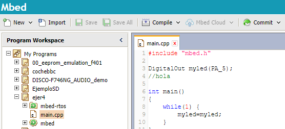
	#include "mbed.h"

	DigitalOut myled(PA_5);

	int main()
	{
		while(1) {
			myled=!myled;
		}
	}
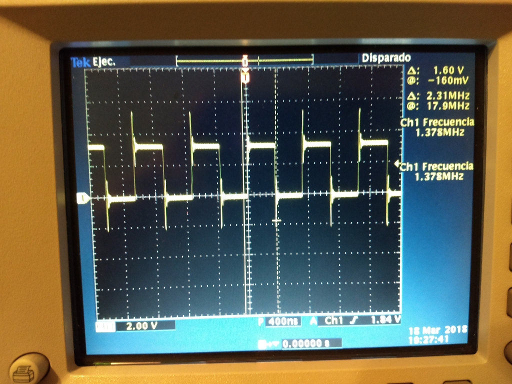
As can be seen in the picture below using mbed is very easy. Its a similar concept to Arduino. It is very easy to develop code using mbed but you loose some control of the micro-controller.
The speed reached using this method can be shown in the picture below. In this case the change frequency have been 1.37 MHz. It is more or less the half of the example developed using the configuration wizard but faster than the two first examples. This demonstrate that first examples have probably a bad configuration of the clock.
5_ Arduino in STM32
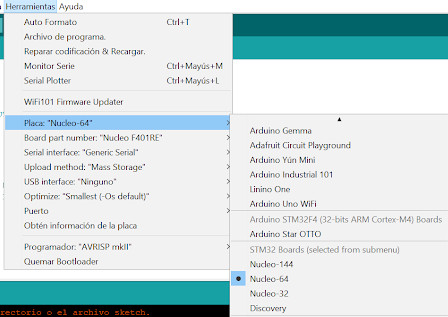
It is not very common but Nucleo board can be programed also using Arduino. It can be done including Nucleo board to the Arduino IDE using this URL, in Preferences.

Then you have to go to the board manager menu and search the STM32 boards including them.

Finally, you have to configure the correct board and the connection.
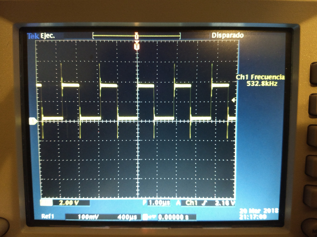
The tested program in the board using Arduino can be downloaded in this link. The result in the oscilloscope can be shown in the picture below.
STM32: Final Results
After changing the clock configuration in the first two examples the results can be shown in the table below.
| Test | Chage Frequency | Perfomance |
|---|---|---|
| Register Level | 8.525MHz | x1 |
| HAL Library | 3.551MHz | x0.41 |
| STM32CubeMX wizard | 3.551MHz | x0.41 |
| Mbed | 1.378MHz | x0.16 |
| Arduino in STM32 | 532kHz | x0.0624 |
The conclusion is that if you use low level register control you can get the faster results from the micro-controller, but it is is the hardest way to program the micro-controller. If you choose a high level abstraction library as mbed you can develop very quick but you lose performance.
ESP32 architecture
The ESP32 is a micro-controller that have integrated Bluetooth and Wifi.
1_ESP32 with Espressif framework
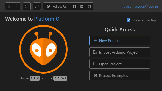
It can be programed using Espressif framework, but to do this easier can be used PlatformIO. To use platformIO, first, you have to install vsCode from this link. Then you have to install platformIO IDE plugin.

Create a new project:
In the configuration wizard you have to choose your board and the desired framework, in this case ESP-IDF.

The code used can be shown below and can be downloaded in this link.
#include#include #include #include "esp_wifi.h" #include "esp_system.h" void app_main(void) { gpio_set_direction(GPIO_NUM_5, GPIO_MODE_OUTPUT); int level = 0; uint32_t* GPIO_w1ts = (uint32_t*)0x3ff44008; uint32_t* GPIO_w1tc = (uint32_t*)0x3ff4400c; while (true) { if (level) { *GPIO_w1ts = 1 << 5; } else { *GPIO_w1tc = 1 << 5; } level = !level; } }
The change frequency is 4.21MHz.

2_ESP32 with Arduino
The ESP32 can be programed using Arduino IDE too. The code used in this case is:
	int toggle = 0;

	void setup() {
	pinMode(5,OUTPUT);

	}

	void loop() {
			toggle = !toggle;
			digitalWrite(5,toggle);
	}
Using this code has been reached only 384 kHz. Again, use of Arduino framework give us a performance drop result.

**BBC Micro Bit
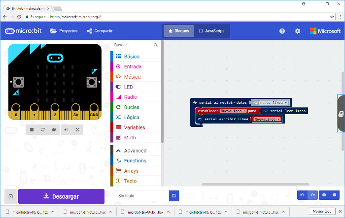
BBC Micro Bit is an small board designed to teach programming skills to children. It is very easy to use, it can be programed using a graphical interface, and when programing code is finished, download .hex file and past it into its memory (USB connection to the computer), simple.

The serial echo example using this board can be shown in the picture below. We do not link downloads to it because it was only for testing and curiosity. :)
DOWNLOADS
_ Arduino in STM32 (Group assign.).
_ STM32 project 1(Group assign.).
_ STM32 project 2(Group assign.).
_ STM32 project 3(Group assign.).
_ STM32 project 4(Group assign.).