Exercise 06. 3D Scanning and Printing
Situation
After the lesson about 3D printing and scanning, on Wednesday 21 February, the assignment for this week was to:
			GROUP ASSIGNMENT:
				_ test the design rules for your 3D printer(s)
			INDIVIDUAL ASSIGNMENT:
				_ design and 3D print an object (small, few cm) that could not be made subtractively
				_ 3D scan an object (and optionally print it)
PREVIOUS CONSIDERATIONS
Before beginning with assignments it is important to understand which printers we have in Deusto FabLab, to know the technologies we can use and its considerations.
We are going to work with these three technologies:
_ Prusa I3 3D printing machine: FDM (Fused Deposition Modeling) or FFF (Fused Filament Fabrication).
_ Form1+ 3D printing machine: SLA (Stereolithografy).
_ Sense 3D scanner.
Prusa I3 3D printing machine
Fused Deposition Modeling (FDM), or Fused Filament Fabrication (FFF), is an additive manufacturing process that belongs to the material extrusion family. In FDM, an object is built by selectively depositing melted material in a pre-determined path layer-by-layer. The materials used are thermoplastic polymers and come in a filament form.

FDM is the most widely used 3D printing technology: it represents the largest installed base of 3D printers globally and is often the first technology people are exposed to. We have 3 of these Prusa I3 machines in Deusto FabLab, mounting 2 more in the next months.
What is important from a designer's perspective is build size and layer height: The available build size of our Prusa I3 is 200 x 200 x 200 mm.

In these machines design considerations to keep in mind are: Bridging, hole orientation, vertical axis holes under-sizing, overhangs, corners, vertical pins, shell and infill, built direction and resistance considerations.
We have made these considerations tests into Group Assignment part below.
It is used Cura 3D Slicer Software in these machines here in the lab. Cura is the friendly face of slicing software. Just load the model, select the quality and hit print. For novices, it makes it easy to get great results. For experts, there are over 200 settings to adjust to your needs, and it supports STL, 3MF and OBJ file formats. Open source and completely free.
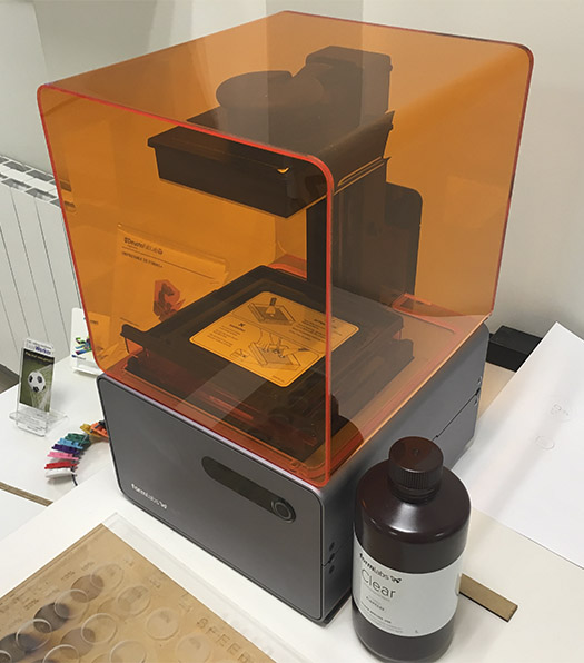
Form1+ 3D printing machine
Stereo-lithography (SLA) is an additive manufacturing process that belongs to the Vat Photo-polymerization family. In SLA, an object is created by selectively curing a polymer resin layer-by-layer using an ultraviolet (UV) laser beam. The materials used in SLA are photosensitive thermo set polymers that come in a liquid form.
The liquid resin is solidified through a process called photo-polymerization: during solidification, the monomer carbon chains that compose the liquid resin are activated by the light of the UV laser and become solid, creating strong unbreakable bonds between each other.
After printing, the part is in a green, no-fully-cured state and requires further post processing under UV light if very high mechanical and thermal properties are required.
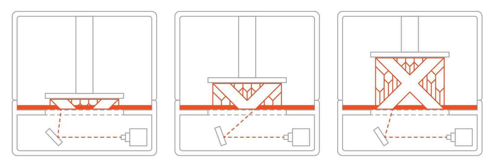
Form1+ is FormLabs first desktop stereo-lithographic 3D printer, and its build volume is 125x125x165 mm. It is a Bottom-up SLA machine, it places the light source under the resin tank and the part is built facing upside down. The tank has a transparent bottom with a silicone coating that allows the light of the laser to pass through but stops the cured resin from sticking to it. After every layer, the cured resin is detached from the bottom of the tank, as the build platform moves upwards. It has lower cost than the top-down (industrial) machines, but the disadvantages are (as we are going to see in the group assignment) that it is not good printing large sizes and it requires more post processing, due to extensive use of support.
Best results are achieved when the designer takes advantage of the benefits and limitations of the manufacturing process. In these machines design considerations to keep in mind are more detailed than in FDM technology, we can see some of them in the image below:
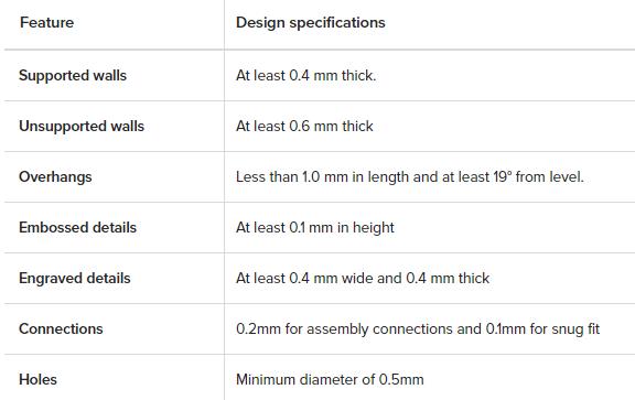
We have made these considerations tests into Group Assignment part below too.
SENSE 3D Scanner
A 3D scanner is a device that analyses a real-world object or environment to collect data on its shape and possibly its appearance. The purpose of a 3D scanner is usually to create a 3D model. This 3D model consists of a point cloud of geometric samples on the surface of the subject.
The collected data can then be used to construct digital three-dimensional models. Many different technologies can be used to build these 3D-scanning devices; each technology comes with its own limitations, advantages and costs. Many limitations in the kind of objects that can be digitized are still present, for example, optical technology, may encounter many difficulties with shiny, mirroring or transparent objects.
Common applications of this technology include industrial design, orthotics and prosthetics, reverse engineering and prototyping, quality control/inspection and the digitization of cultural artifacts.
We haveSense 3D Scanner in Deusto FabLab. It is portable and practical, it connect to the pc through USB cable, and its software is very easy and intuitive to use.

The Sense 3D scanner gives you the ability to observe a scene in three dimensions and then translates the observations into a 3D model. You can then use various Geomagic applications to translate the scans into information such as: Identification of people and their body properties, classification of objects such as furniture, packages, and so on measurements such as size and volume, location of walls and floor.
We have made some body scanner works, detailed below in group assignments.
GROUP ASSIGNMENT
My FabAcademy mate, Javi Vicente, and me have been testing design rules for those two 3D printers.
We knew that in Thingiverse or Yeggi websites we could find some 3D printer testing files, so we download 3 of them, and made tests with them to know our printers limitations:
FDM/FFF
We have made two 3D printer tests. [You can find here 3D files: 1st test file and 2nd test file]
The first one is a smaller part (see the image below, named Test FDM A), 50x50 mm, but we thought to begin with this one, because was the first time we were using this machine.
We took the .stl file from the compressed file we downloaded using Thingiverse, and we opened it in Cura 3D Slicer.

Cura Slicer allows us to create our machine personal settings (if it is not one of commercial models Cura has in its database), and not only with the print area size, we can create a setting for each Prusa I3 we have in the lab. We created one with 2.85 mm Material Diameter, but we can have different one too for when we are using 1.75 mm.
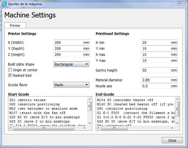
We can also use recommended configuration (which is very easy and with almost no option) or Custom one. If you go to Custom configuration, you besides can customize parameters menu, depending on what we want to configure.

The setting list we have used for Test A is:

So, if we take Cura project for this first test, and activate Layers View, we can see how much layers and how is going to make our printer in an hour and 5 minutes.

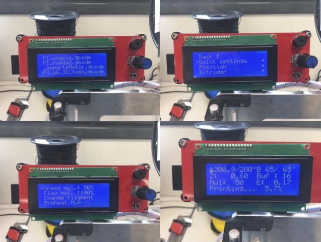
Saved the file to a SD card (it save in .gcode), we went to the machine, Prusa I3. We insert the SD and then a list of projects appeared in its screen. We selected our printing project using the wheel-joystick it has.
The menu of the printer is very simple, tree-structured and with a back option in each screen or mode. The use of the menu is always with the wheel-joystick it has, and it has also a Stop button to stop machine immediately if it is needed.
The only thing we changed, while it was heating up, has been Speed mul to 50% of its speed. It is good to do this in the first layers to see if the printing process is beginning well.
It heat up the Bed Temperature first, then the Extrusion Temperature.
When the machine is heated up it goes to the origin, and then it goes directly to make the first layer. But is important to configure at least Skirt build plate adhesion, due to the exit-delay of the extruded material.
In this case, Deusto FabLab Prusa printers have vinil adhesive pieces in the hot platforms to ensure that the printed part is not going to Warp.
We have to be attentive in this first layer, if it is going well we have only wait until it is finished.

The result of our first Printing Test is next one:

It has, being a Low Quality printing, really good finish and we can check hole diameters for example, but we can’t see the numbers or small details. So we made next Test B in a better quality.
Test B is a larger part, 100x100 mm, and we are going to print it with the option of Profile: Fine 0.1 mm and all rest of settings same to Test A.
We took the .stl file from the compressed file we downloaded using Thingiverse, and we opened it in Cura 3D Slicer.
Whole process in the images below:


The result has been better than the first. More detailed, and even though we did not think it was going to come out that way, it has printed well up to the angles of 85º. :)

SLA
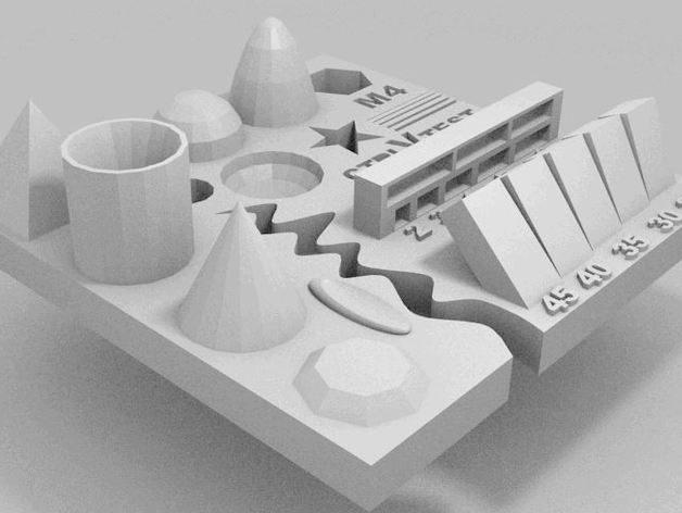
Test part we have chosen to print it in SLA is the next one:

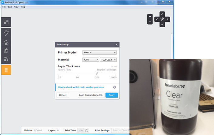
It that case Form1+ printer has its software Preform, and the first thing to do is to select the material we are going to use and the quality of the printing. We choose Clear photopolymer and not the higher but a very good quality: 0.05 mm layer thickness.
We opened the .stl file in Preform, and it follows three steps: Situation (XY position), Orientation (angle) and Supports.
In bottom-up SLA printers overhangs and bridges need to be supported, but minimizing the cross-sectional area of each layer is the most crucial criterion: the forces applied to the part during the peeling step may cause it to detach from the build platform. These forces are proportional to the cross-sectional area of each layer. For this reason, parts are oriented in an angle and the reduction of support is not a primary concern.
It is such automatic process (it has buttons in each sections to it) but reading in FormLabs sites it is better to do the orientation thereby: 60º Y + 30ºZ.
The support, being very little parts, with the minimum (touching) point, and we have duplicated the file for doing one with internal supports and the other without.

We send them two to the printer, which name is ImpartialDuck ;)

We have to be sure that the platform is well mounted and the resin tank is full of material (between Min and Max marks), and GO!
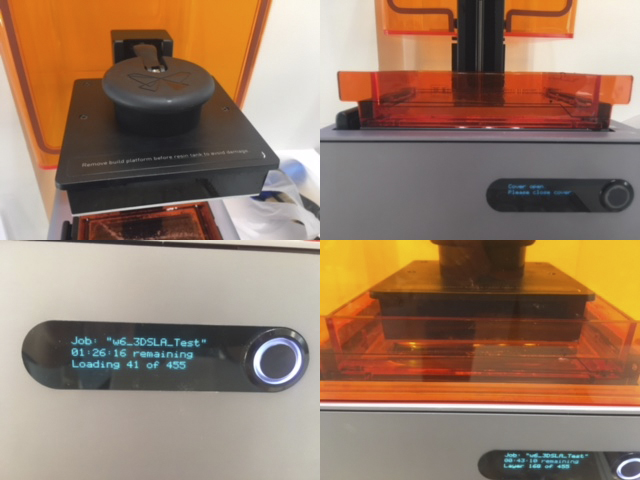
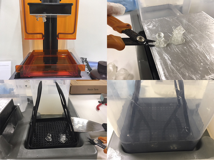
This first SLA print has gone wrong:

They are not entire parts. What could be the problem? We analyze the platform and it was very dirty, we unstick material, and helped with Ethylic Alcohol we cleaned up it.

In this case, for the second test try, we thought that it was interesting to print a little sphere too: in those kind of parts we can see the continuity of the printing layers in an easier way.
So we prepared it in Preform, and we continue printing. And it was wrong! First layers weren’t attached to the platform.
Why? After reading some all-around world users experience we realize that due to the platform material (aluminum) after months of use of the machine (it has 3 years) has been erode. And the origin of the machine in its initial times has been changed, it was upper than when it has been acquired.
The solution has been to do Fine Tuning to the Form1+. After probing it with 0.1 mm and having a wrong attachment of first layers to the platform, we made a test with 0.2 mm fine tuning parameter, and woala! It went well and we print the sphere and the test file we have downloaded.
We took the resultant parts and we made the process of cleaning them. (Deusto FabLab has planned to acquire Wash and Cure system in next months)

After it, and with the illusion of testing the capacity of this machine, we scale test file x3, and we send it to print. But there is something wrong in the machine which is making the print only till a layer, and then fails. So we have work analyzing this error and finding which is the solution.
We continued to make tests, and always was the same: It printed first layers and then nothing. Why? Finally, we tried to do it with a no fine resolution, with a fastest one (the worst resolution 0'2mm) and it made it well!
We realized that material we are using, resin we have, is a little bit "old". We opened it months ago, and the photopolymer resin loses properties fairly quickly once the can is opened. We will do more tests when we buy new material.
INDIVIDUAL ASSIGNMENT
Design and 3D print an object
I had to design and 3D print an object (small, few cm) that could not be made subtractively, and I thought to follow my final project way and make a special Flower Pot.
Some plants don’t need to be watered from upside, they need to have a close water quantity and they take it when they need it using their roots. For example: carnivorous plants.
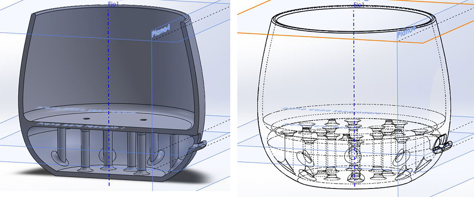
This kind of flowerpot is always made by two or more sub-parts. And I thought to do only one part piece. I project it using SolidWorks.
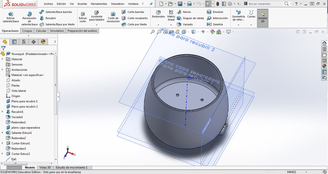

Then, I re-design it thinking is the characterization of our Prusa I3 machines. One of the most important thing to modify has been to create my own structure pillars in the inside-down part, because I thought that it would be impossible to have an area where water will flow freely, with supports created automatically in Cura.
Another thing I have learn is to change the material. I have Black PLA in the FDM machine, Prusa I3, I was going to use, and it is not a good color (it takes up too much hot) to a plant. I change it to white PLA material.

I printed it in FFF/FDM with the parameters we used in the characterization process and it went very well!
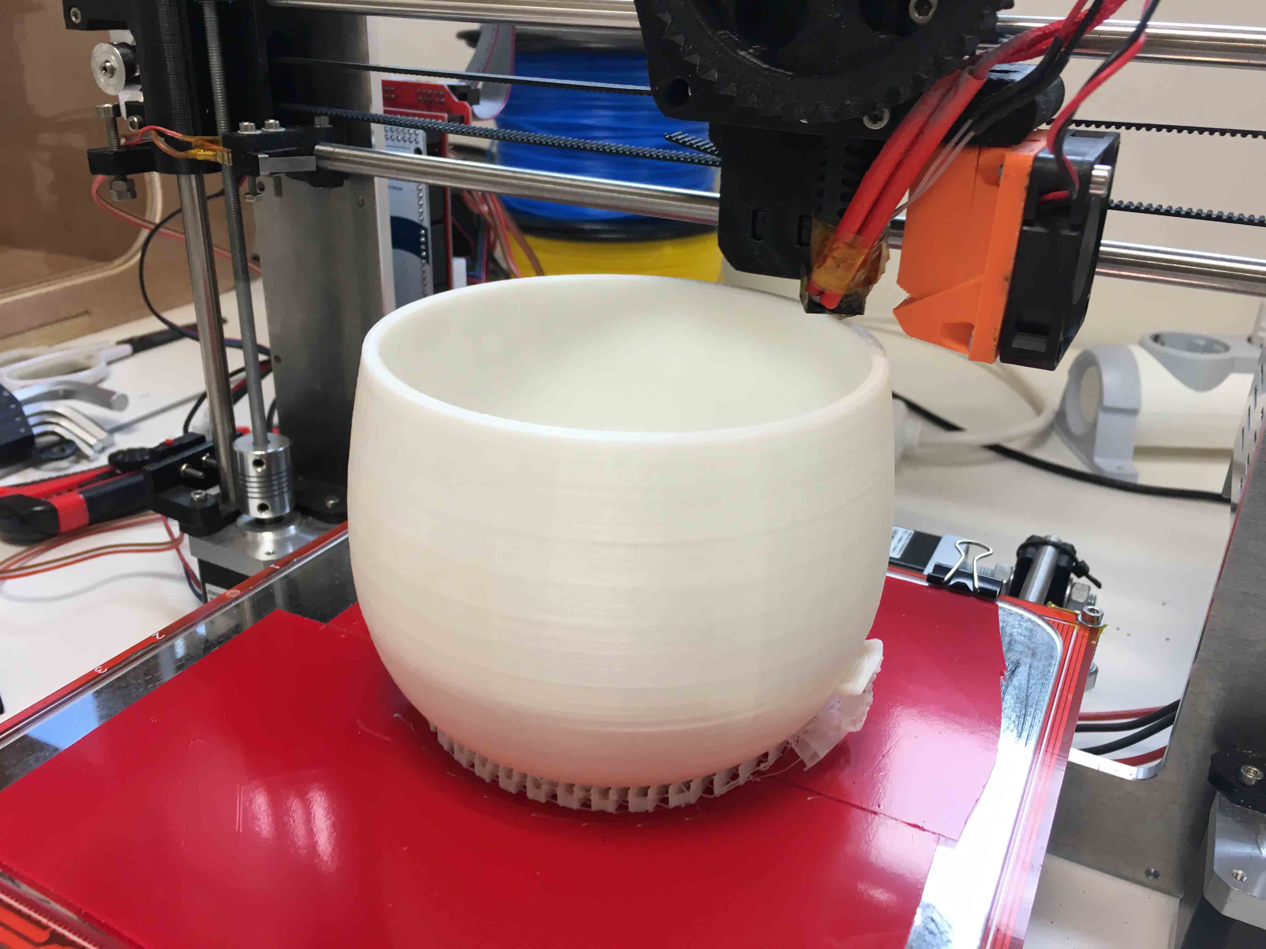
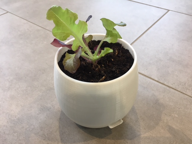
Now, I have to clean it, make test of water-tightness, and place a plant with this characteristics inside!
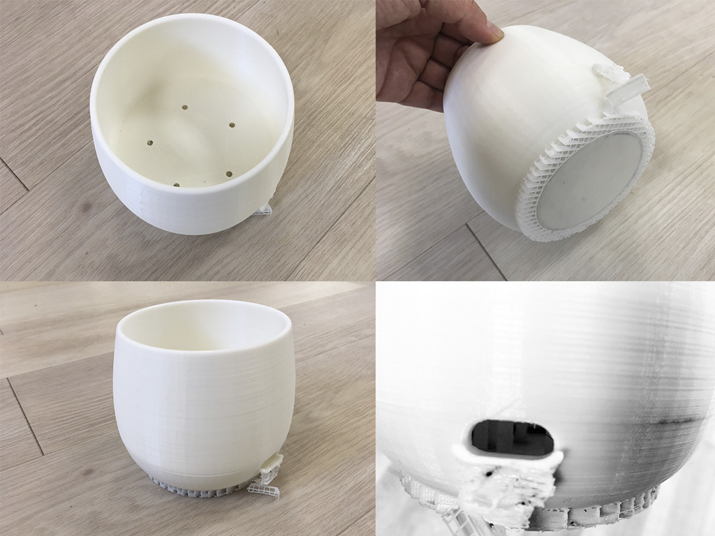
And I proof its water tightness:
3D SCANNING
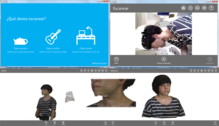
For 3D scanning we used Sense scanner we have in Deusto FabLab, and its software to scan, which is very simple and intuitive.
We scan each other using a stool, and twirling, due to Senses short USB cable.
First question it made us has been what we wanted to scan, and first time we choose Person and then aBust. But it went wrong due to computers low capacity. It needs a good graphic card and it hasn’t, to scan the details Sense wants to take in this scan modality. The model has been scanned halfway.

So in the second round we choose Object and then Medium Object. It has been easy to take our 3D scanning, and then modifying them using software’s editing options.
We export them in .stl and .obj., you can finf files here.
Also I took my .stl file and I opened it in Cubify Sculpt software we have installed in Deusto FabLab, and I has been probing its options, it has been fun!

Finally, we send those three files to 3D printing in Prusa I3 FDM machine, using Cura (Sense direct .stl files and Sculpt file).

And this is the result! :)

DOWNLOADS
_ Flower-pot 3D files(SW and STL).