As a fan of platonic solids I decided to do a Dodecahedron for my press fit kit assignment.
I tried to use Autodesk Inventor to design but I discovered the settings were off and it was stopping my progress(as it did in week 3) so I changed to Fusion 360.
It took a bit to get used to it, but soon enough I was back on track.
My first attempt was a heptagon with 60 mm sides.
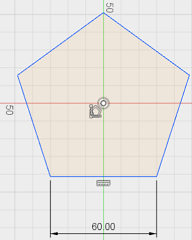
After I sketched 10mm squares as the fitting pieces for the dodecahedron to hold together.
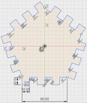
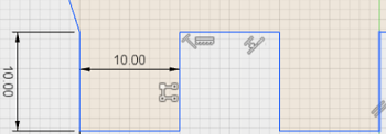
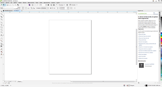
In the lab they use the corel software to make the machine work so I had to download Corel Draw.
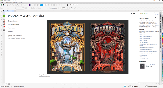
Next I had to create a new project.
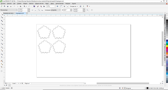
Following I imported my pentagon sketch which I exported from Fusion in a .dxf format and copied it 4 times setting it where I want the laser to cut the MDF(compressed cardboard) board.
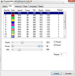
Next I selected the cutting parameters:
- Speed: 30.0
- Power: 98
- PPI: 300
Finally I turned the extractor to avoid fumes and debri from floating around our breathing atmosphere and started cutting.
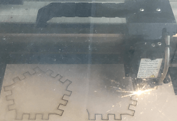
I cut 4 of them and soon I found out there was a margin to consider due to the kerf (the space the laser incinerates when it passes) as the pentagons didn't generate enough friction to stay together (they were loose).
I discovered the KERF was 0.2mm so I got to it.
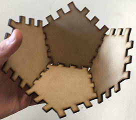
On the next attempt I designed a variable LENGTH = 40mm for the heptagon's sides.
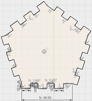
Once this was done I segmented the side in 6 parts for the 3 rectangles and 3 spaces between them.
The adjusted dimensions were:
- 4mm long and (LENGTH/6 + 0.35mm) wide for the rectangles as the kerf was taking material from the rectangles reducing their dimensions.
- (LENGTH/6 - 0.7mm) for the spaces between them since the kerf was increasing their width.
I laser cut 2 pentagons and they didnt fit so I adjusted the variables and did it again.
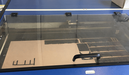
The second attempt also failed but I was getting closer.
On my final attempt the dimensions were:
- 4mm long and (LENGTH/6 + 0.1mm) for the rectangles.
- (LENGTH/6 - 0.2mm) for the spaces between them.
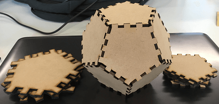
Finally, it fit and I had my dodecahedron as shown in the picture below (Next to the 2 results from the failed attempts).
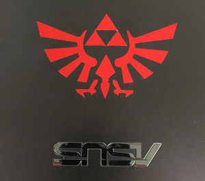
I decided to do a vectorized image of Zelda's Logo. I downloaded Corel X7 and once in I imported the picture of Zelda's Logo.
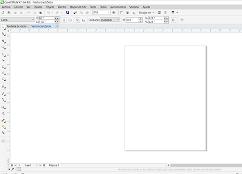
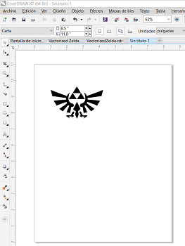
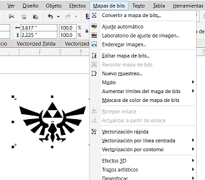
I found out there was an option to quickly vectorize any image on Corel. The commands to do so are: Bit Map>Quick Trace (My image shows the translation for this command). This option generates a vector image under the main image.
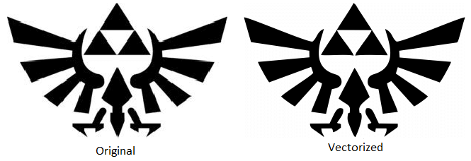
Following this I removed the color of the vectorized image by Right Clicking it and then Ungrouping, following this I emptied the infill using the Interactive Infill Tool.
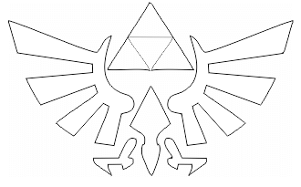
Next, I selected the printer (Cutter) Roland GX-24 by pressing: control+p>preferences>Roland GX-24.
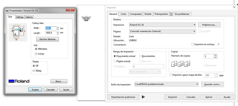
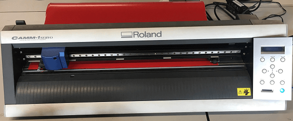
After I started the cuttting operation.
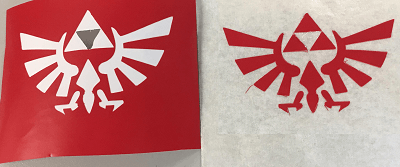
Once it came out I had to use a special tape to remove the sticker without breaking the pieces.
Download the original files from the links below:
Pentagon Design: Fusion (.dxf file)
Vectorized Zelda Logo: Corel Draw X7 (.cdr file)