Week 9:
Embedded Programming
Programming the LED and Button
The goal of this week is to program the circuit board which I made in electronics design's week.
First I wanted to show you the board I did in Week 7 for electronics design. So, I started from the very first "FAB ISP" Week 5 - "FAB ISP" to make the LED and the button in active mode which were super Awesome experience for me in programming world!!!
Hero Shot of the final outcome ^_^
Again to see the steps and the process of making this board, go to Week 7
Before we start, the Eng.Hashim gave us a session on how to programme using arduino.
So the first thing we did is Downloading the Arduino ..
In Arduino follow these steps:
- tools
- board manager
- We need to copy the link from this website,and copy the link you see in yellow box as the photo showes to add the ATTiny 44.

After you copy the link from the page or website given
- Write att
- press More information
- Install
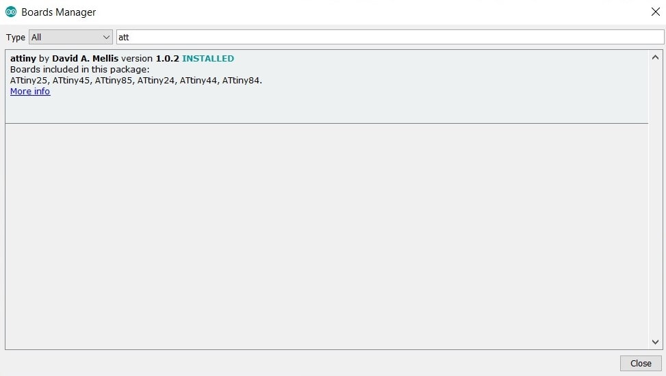
ATtiny 44 Board
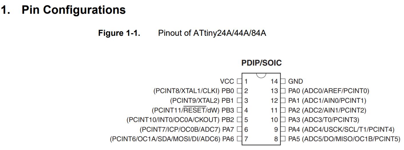
The datasheet helps me to know more about the pinout diagram for example in pin configuration XTAL means crystal so when i draw the eschematic I connect the Crystal to the microcontroller attiny 44 through the PB0 pin which has XTAL1 means Crystal as mentioned before.
This youtube tutorial gave me more information on Arduino, presented by Jeremy Blum.. thank you
Well, before I talk about how I programmed my LED and button I want to mention how reading the FTDI datasheet helped in fixing my problem in enabling the programming to be completed!!!
I put the connector pin in oposite way which i didnt connect ground to ground and etc.. for the rest, So that's why I couldnt do the programming, However, Our classmate Salama is really super electronic engineer ^____^ after she had a look at my board, solder, connections, she pointed to the FTDI connection. I had it the wrong way, So I shouldnt ignore the importance of orientations, see the picture below.
**NOTE. to get the right pin out I have to check the cable and whats written on it.
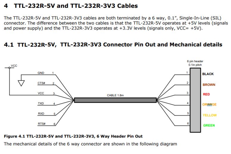

I keep getting this window till I put the pin connections in correct way.
Look at the msg here,,
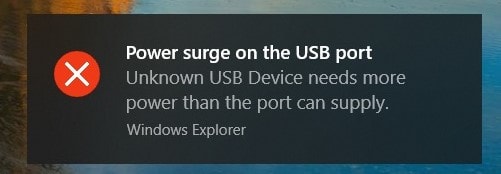 After the help I got from my classmates and Our professor Wendy I moved to connect successfully the FAB ISP "first board of electronices production week" + the board we created in week of electronics design with arduino software.
HERE is my two instructors =) ..


rc problem !!
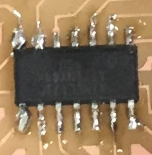
 This "rc" problem is because of ATTiny orientation -_*!! Thank you Wendy for checking my board and helping me out to fegure it out. beacuse honestly when the LED wasnt programming I thought there must be something wrong with the connections again! But Wendy really spotted one so tiny thing which she had to use the magnifier to see this mistake I did an-accidently!
So, for beginning we only asked for these 2 changes. and to make it easier just open both windows and you can see how numbers will help you with Arduino.
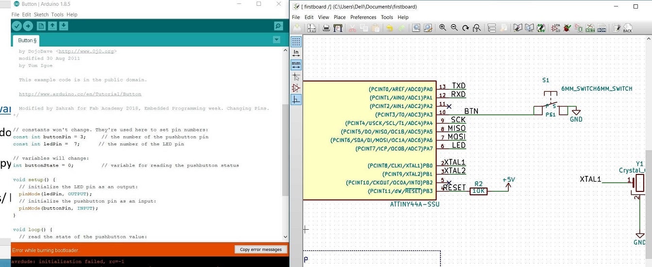
Button
The change I made in arduino code are the highlighted ones - pins and the comments -
Blink
Im so glad being able to program the board and yeah thanks Wendy for the help in videoing my board here,, But there is a delay in the blink.
Adding pull up resistor
ATtiny 44 Data Sheet
Well, this helped me to know that from BP3 I could add the option reset internally, which helped me to change this option only through programming and not by adding the resistor physically on the circuit board.
becuase of adding the pull up resistor in the code the problem solved.
otherwise I could add a resistor to the button "the input"
So because of already the pull up resistor exist in the attiny chip internally we just need to activate it with the code. you can check the edited code here.
