5. Electronics Production
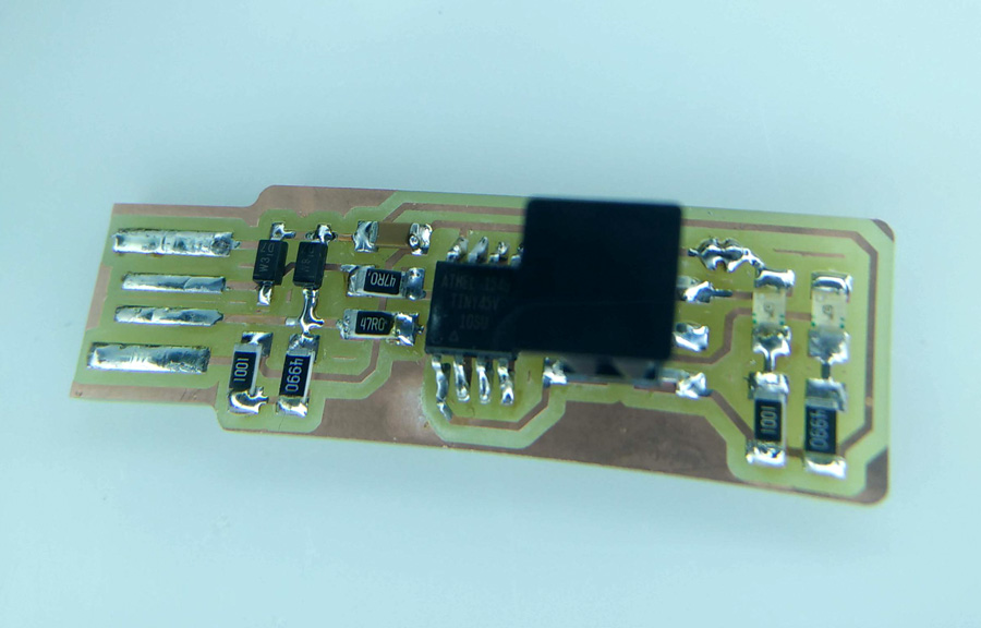
My journey into the unknown world of pcb boards began with reading Ali Shtarbanov's page (and associated links) on Demystifying the FabISP. This made sense of some matters concerning PCBs but also opened the flood gates for a number of areas I knew nothing about. I found the best way to understand was to get hand-on as quickly as possible.
Preparing PCB File
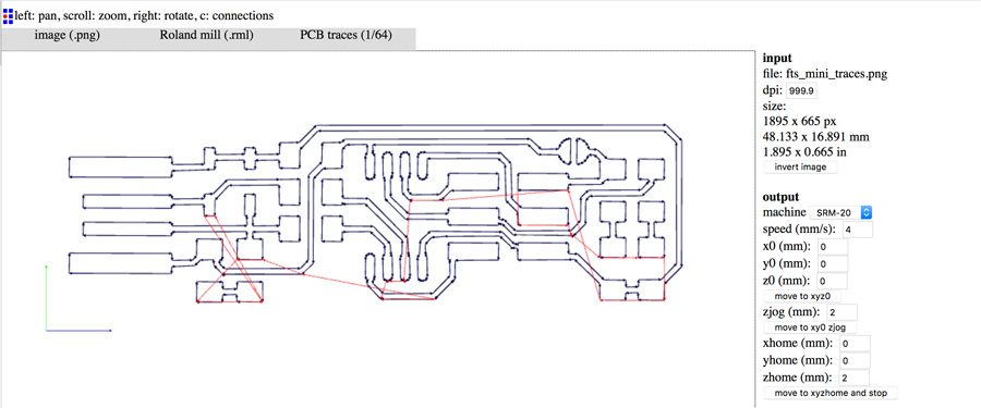
I returned to fabmodules and uploaded the pcb file (zip file). I entered dimensions based on the successful cuts from our group work on the Roland SRM-20. I also used the preview system, to check that the cuts were not to thin or overlapping.
- Machine SRM-20
- Speed 4
- X0/Y0/Z0
- Zjog 2
- Xhome/Yhome 0
- Zhome 20
- send command / server NO CHANGE
- tool cut depth 0.03
- tool diameter 0.4
- number of offsets 4
- offset overlap 50%
- path error 1.1
- image threshold 0.5
- sort merge diameter multiple 1.5
- sort order weight -1
- sort sequence weight -1
Roland SRM-20
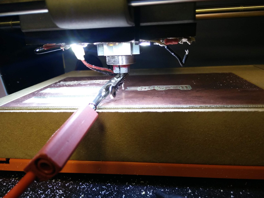
As a group, Adel, Thierry and myself reviewed the characteristics of the Roland by through a series of test cuts. This is dicussed on the group assignment page.
Returning to the individual project, I applied used polysterene to protect the fragile cutting blade and ran the spindle for five minutes.
Zeroing The Axis
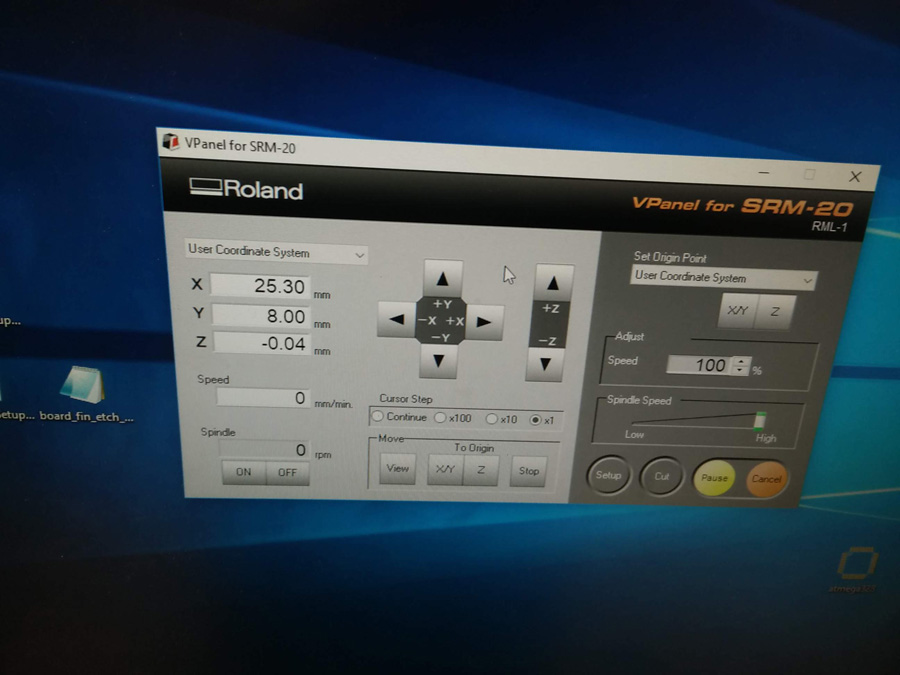
It is necessary to zero the x/y and z axis on your copper plate before running the cutting spindle. For the x/y, it is simply a matter of position the spindle by eye and selecting the Set Origin X/Y button: consider that the point selected is the bottom-left in your file.
I had some challenges regarding the cutting: The z-axis proved challenging to control, especially when extremely close to the board. Varying the Cursor Step from Custom down to x1 provides shorter and shorter movement down the z. If you're unsure, go with the shortest option (x1) so there's no risk of plunging the blade into the copper. A multimeter is used to indicate contact with one alligator grip attached to the spindle, and a probe touching the copper. When the multimeter beeps, the spindle is touching the surface. At this point, press the Set Origin Z button.
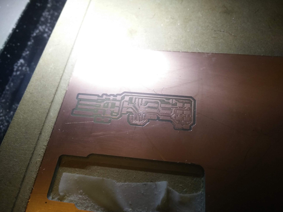

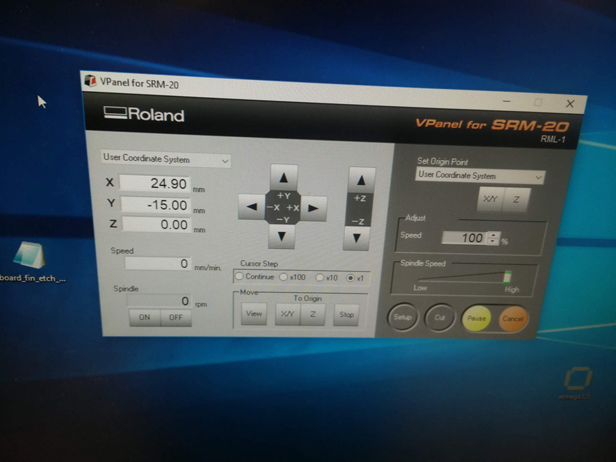
My first test cut too shallow, and it was necessary to adjust the cut depth. It was at this point that I considered Vincent's advice about selecting three diagonal points to take an average z-axis. This took some time (as there was other cutouts to avoid) but I managed to gain an average of the three. On my second attempt, it cut deeper and had a good finish.
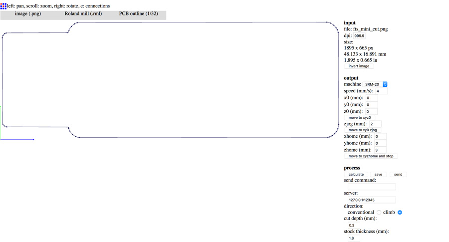
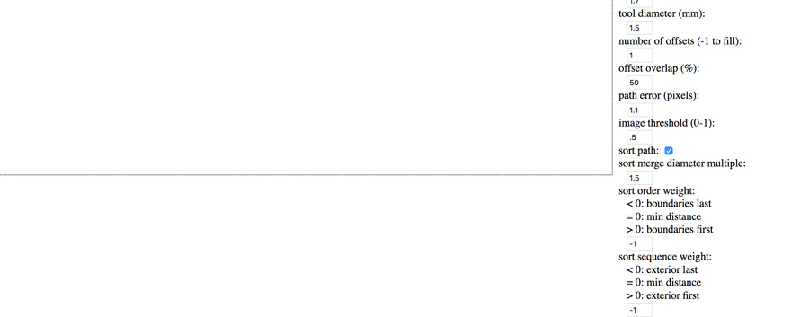
After returning to Fabmodules to prepare the outline file, I had to change to a different cut bit. The x and y axis were left the same, but the z-axis needed to be recalibrated.
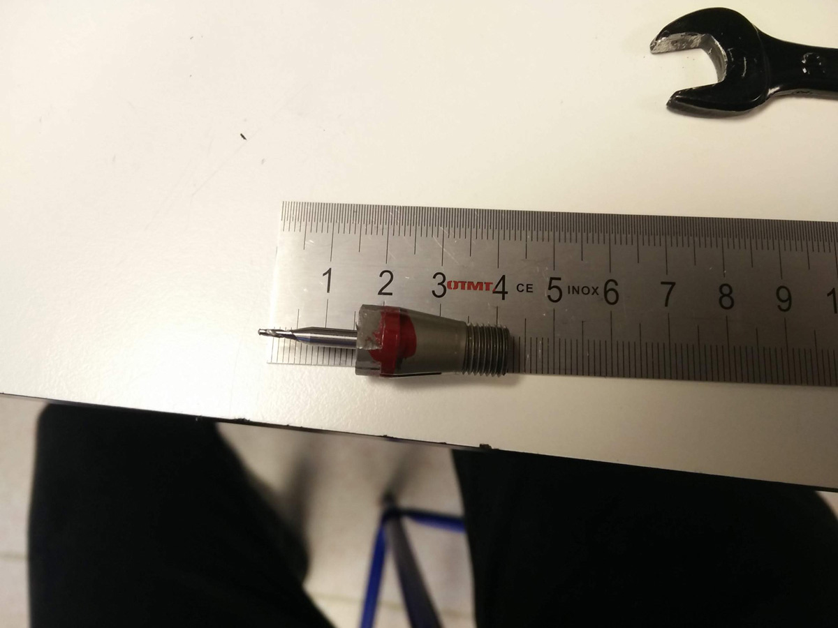
I measured the distance of the blade outside the collect, comparing it for the trace and outline. I started with 20mm then tried 12mm, and later 16mm. 16 mm worked well for both cutting exercises.
On running the outline file, there was an mistake – the cut went over my trace in the corner. I had to redo both the trace and the outline on another part of the board...
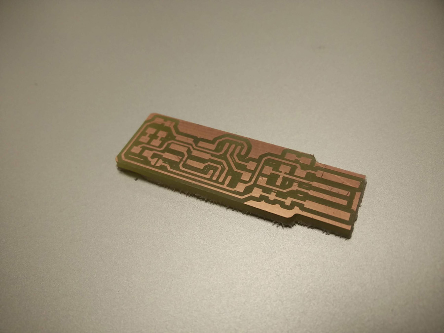
Finally, I had a successful cut.
Solder Practice
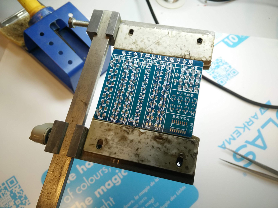
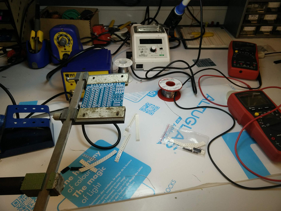
The next major step was soldering practice. I started by using the practice board with an array of different sized soldering positions and components.
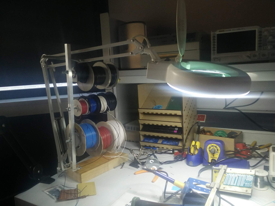
Stuffing
I used a wet sponge to soak up any excess solder on the tip. The overhanging magnify/lamp was invaluable to check soldered joints as I went along.
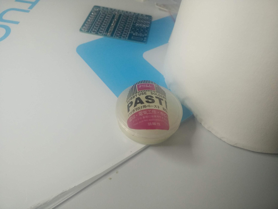
Solder paste was applied to the board to remove the coating which was present on the board. Varied size of tweezers allowed me to grip the component, even when they were very small.
A small fan ventilator was positioned nearby, to remove any excess fumes. I used cellotape frequently to stop the board slipping whie soldering.
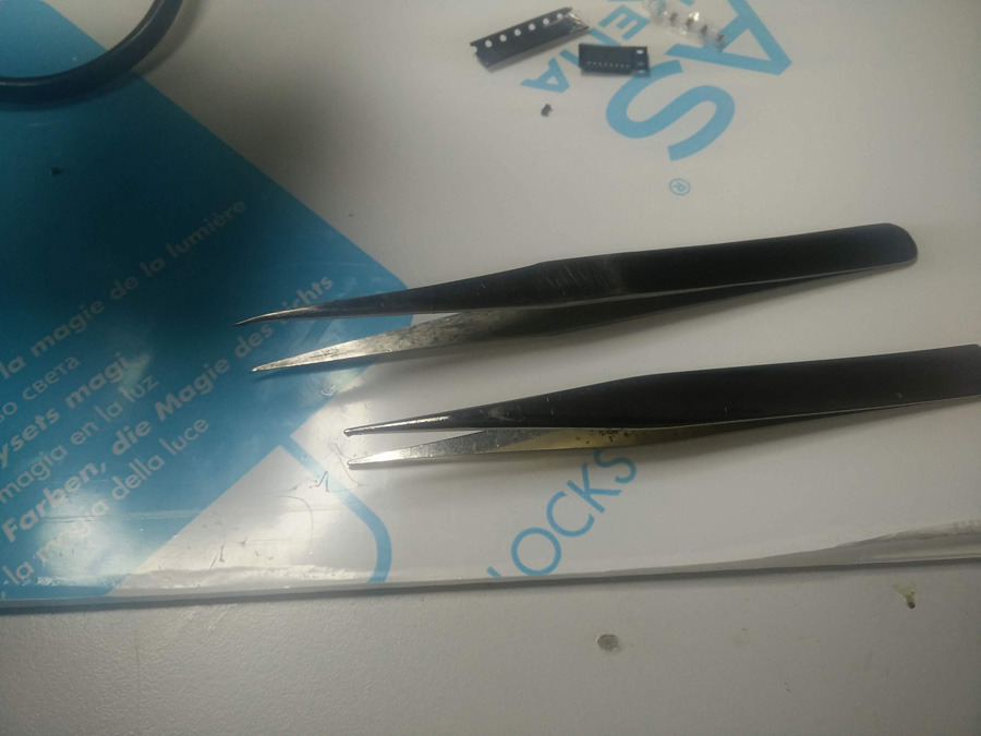
I started with small resistor, 512, attempting to heat the solder and make it 'smooth and shiny'. This took a great deal of practice and it was a challenge to do it consistently, especially with smaller parts. I practiced placing the components in position, flat and straight against the heated solder. When I had mastered 512, I moved to an even smaller resistor, SR1. I was less consistent with this tiny piece, but knowing that the assignment parts were larger, I moved on to the three position component.

The three position component was more challenging. I had to rotate the board repeatedly to get the appropriate approach to the board. I used a similar approach with the YL-50 position (bottom-right corner). The required component had 16 legs, which required soldering in a tight space. I found I found I had improved my soldering ability at this stage and managed quite a clean connection.
Soldering PCB
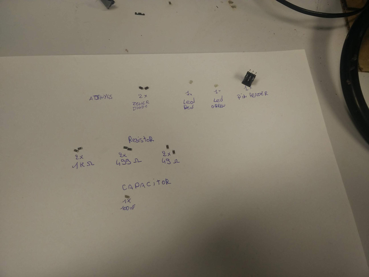
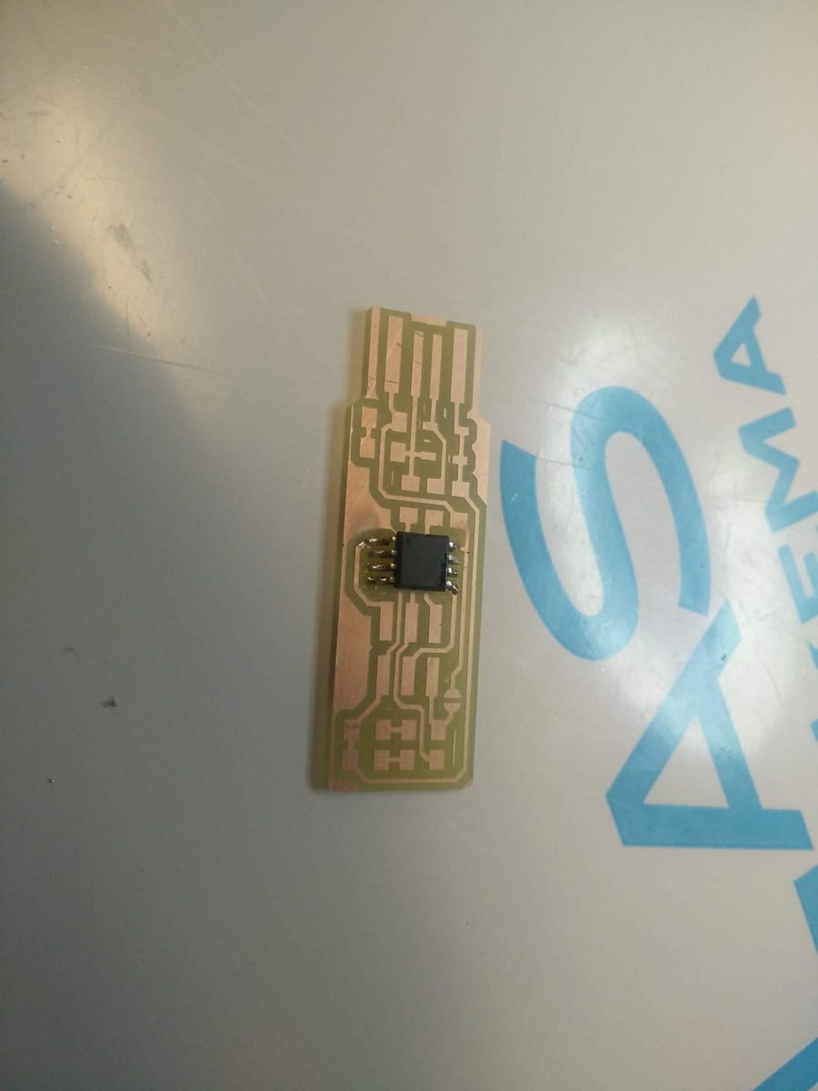
It was then time to solder for real. I started by gathering the required components for the final pcb board – Thanks to Adel's sheet, I was able to lay out my parts in a consistent manner from the many folders in a Fab Lab. I started by soldering the ATtinyin the middle of the board. I achieved a reasonably clean series of joints. I continuously referred to the tutorial drawings to make sure I was in the right location and orientation, for example, that the circle on the ATtiny was in the right position.
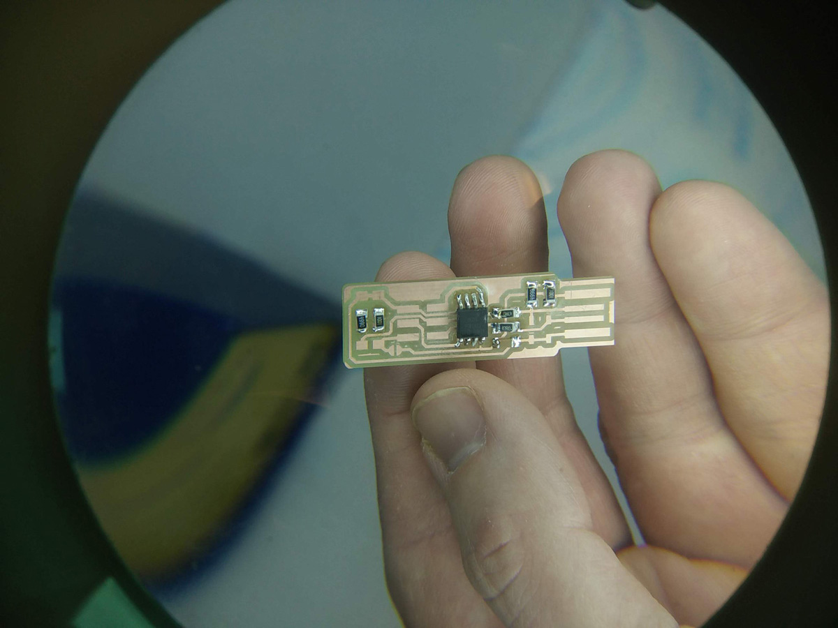
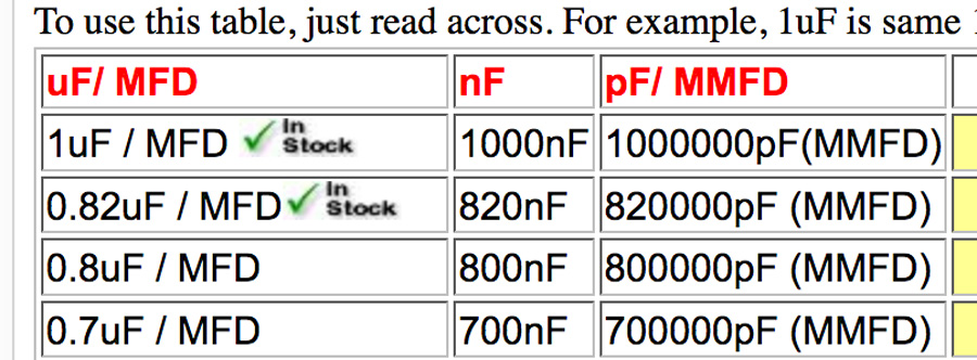
I progressed quite quickly with the six resistors and one capacitor. I read about capacitors on justradios.com to understand which the difference in amounts (see table below). I used the magnifier to check the joints on a regular basis.
For the zener diodes, it was necessary to check the orientation by comparing with information on evil scientist.com. For the LEDs, Thierry and I analysed the 'T' shape on the back of the component and found that it should run toward to the resistors below. *UPDATE 27/05/2018* This is not always the case - For Network & Communication (Week 14 I found that the 'T' ran away from the resistor, to GND.
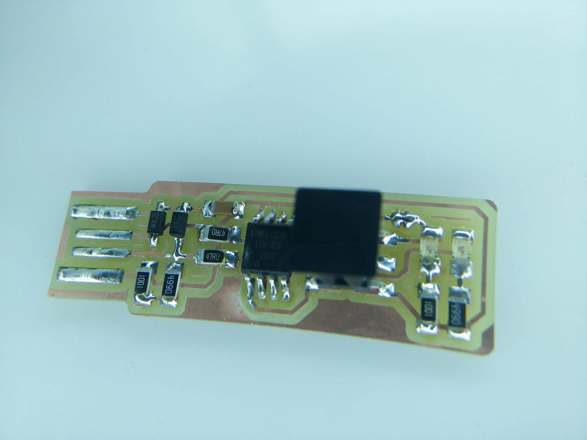
The final pin header proved more challenging to position because of its shape. When it was complete, I added the solder to the front of the usb connection and chipped off the exposed copper. I then created the jumper, bridged for now.
Testing PCB
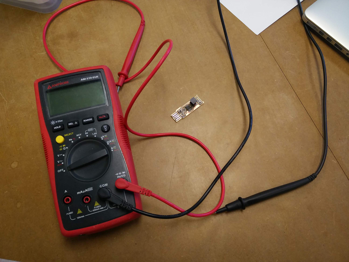
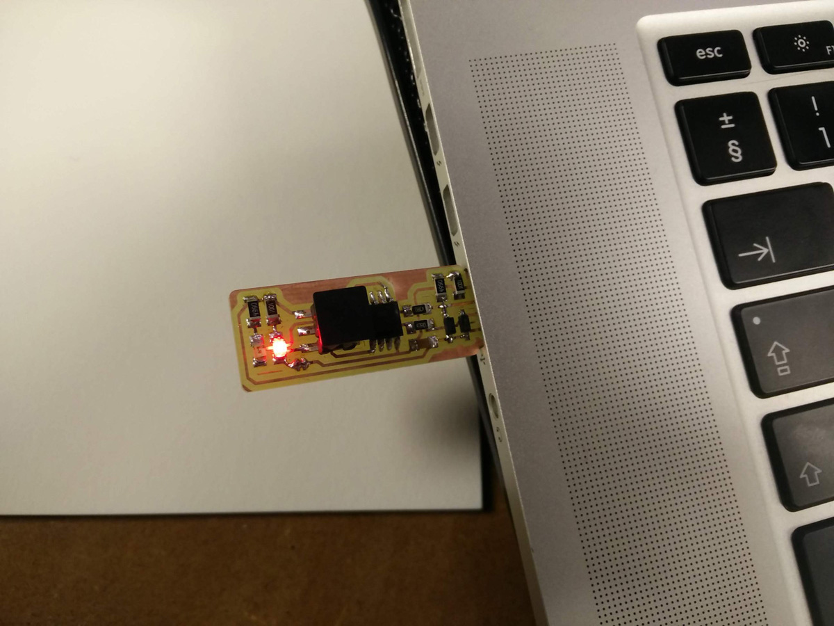
I used the multimeter to test different strands of the exposed copper with the soldered components. Next came the big test, plugging it in! The red LED appeared with shining glory. Then I read in the Fabacademy tutorial we should only plug it in with an extention cable...so with the cable at hand, I prepared to plug my pcb board in another time.
Software for Programming
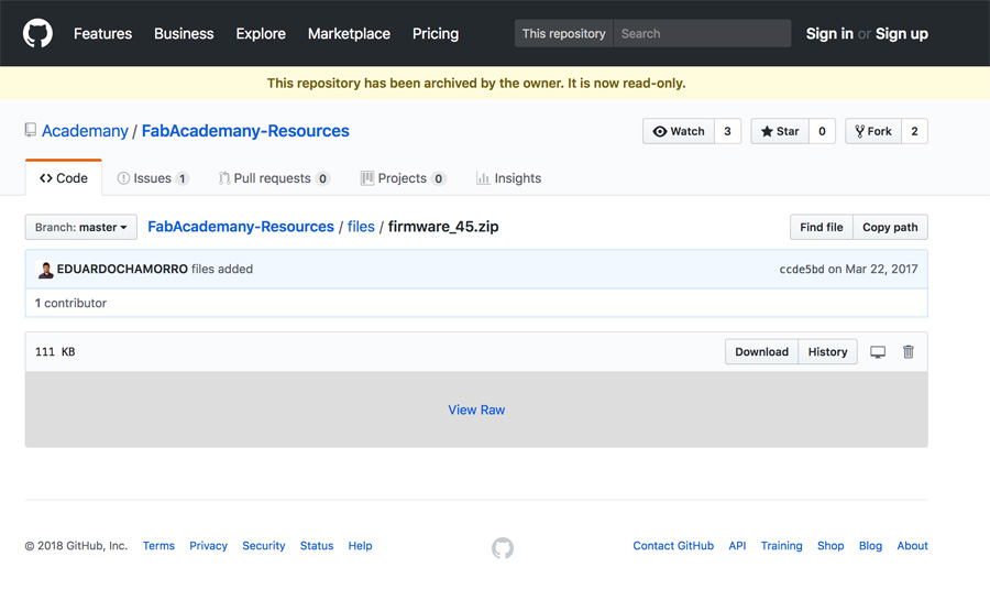
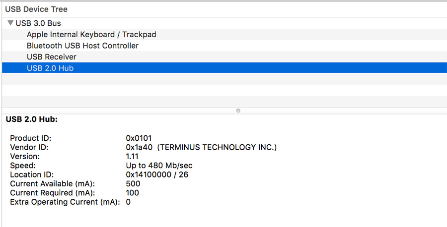
I inspected the System Requirements and as expected, the pcb board did not show up as a USB device because it has not been programmed yet.
In order to program my pcb, I needed to use Vincent's FabISP as a programmer. The FabISP is a more complex version of our USBtinyISP and was laready installed as a programmer from a previous Fab Academy. I connected the wires to the pcb board pins in the appropriate colour combination as shown in the image below.
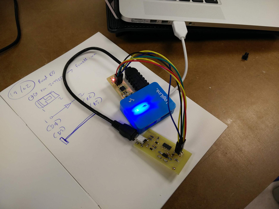
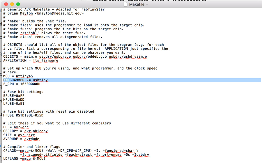
It was necesssary to download Crosspack and restart the computer. I downloaded the firmware source code, using the Terminal line, I ran 'make' within the folder. Opening the Makefile, I saw that usbtiny was already listed for the programmer, so I was now able to plug-in the pcb board.
I ran 'make flash' in the terminal line and the following code appeared,
canalip38:fts_firmware_bdm_v1 benadamson$ make flash
avrdude -p attiny45 -c usbtiny -P usb -e \
		-U flash:w:fts_firmware.hex

avrdude: AVR device initialized and ready to accept instructions

Reading | ################################################## | 100% 0.00s

avrdude: Device signature = 0x1e9206
avrdude: erasing chip
avrdude: reading input file "fts_firmware.hex"
avrdude: input file fts_firmware.hex auto detected as Intel Hex
avrdude: writing flash (2488 bytes):

Writing | ################################################## | 100% 1.86s

avrdude: 2488 bytes of flash written
avrdude: verifying flash memory against fts_firmware.hex:
avrdude: load data flash data from input file fts_firmware.hex:
avrdude: input file fts_firmware.hex auto detected as Intel Hex
avrdude: input file fts_firmware.hex contains 2488 bytes
avrdude: reading on-chip flash data:

Reading | ################################################## | 100% 2.56s

avrdude: verifying ...
avrdude: 2488 bytes of flash verified

avrdude: safemode: Fuses OK (H:FF, E:DF, L:62)

avrdude done.  Thank you.

canalip38:fts_firmware_bdm_v1 benadamson$

When I plugged the usb back in it was still not detected. With Thierry, we considered whether it was a soldering issue, but the fact is the programming of the board had been successful. I decided to proceed with cutting the jumper bridge.
Making a Bridge
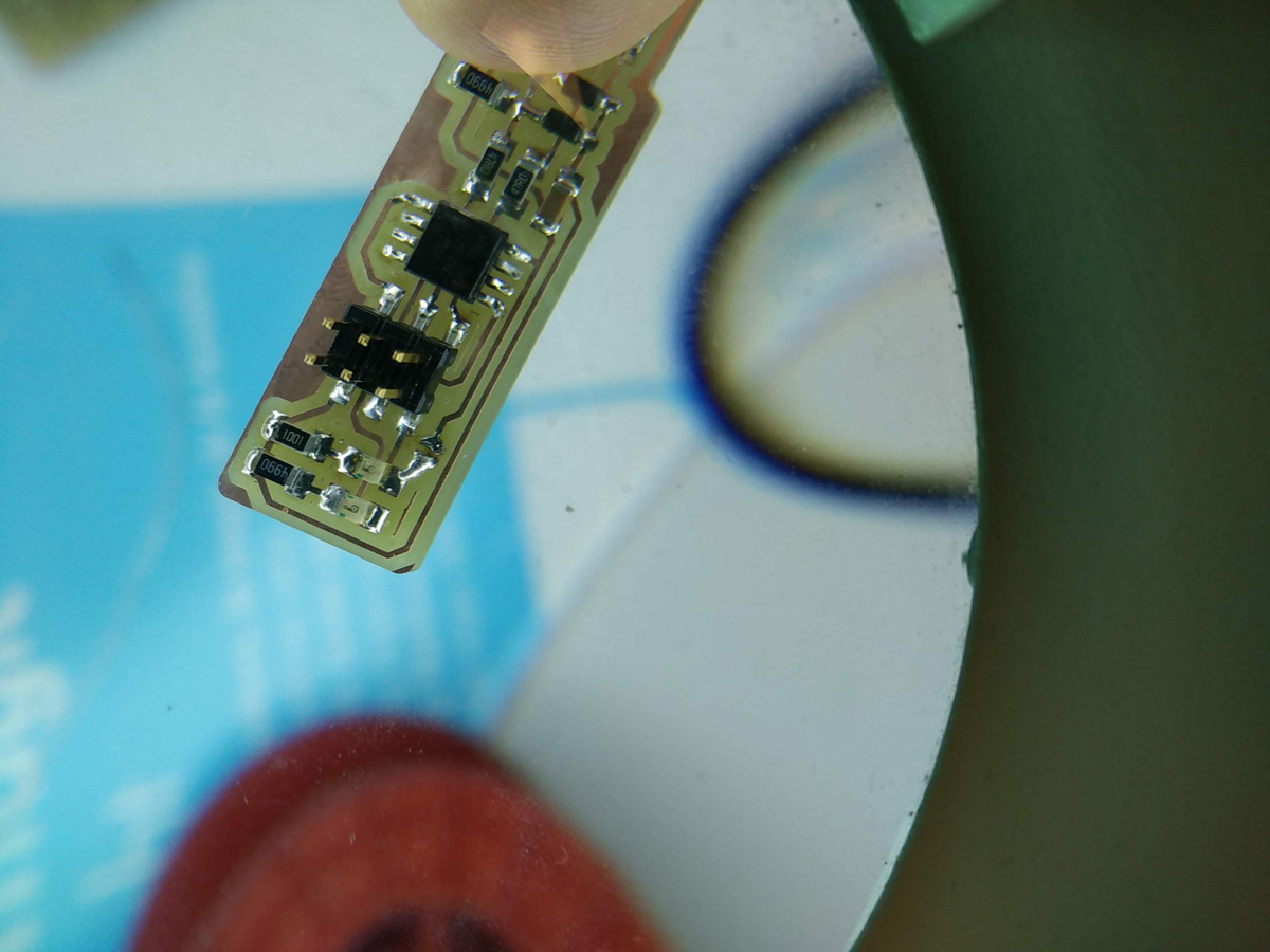
I used a piece of copper wire to smear off the excess solder in the middle of the jumper.
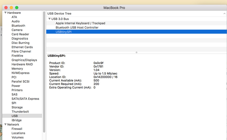
I plugged the board into the usb port and it failed to detect. I tried it on several different ports and computers but it failed to appear. As a group, we reread the tutorial and realised it was necessary to complete a final step to convert the board into a programmer. I ran make rstdisbl and the USBtinyISP was detected! Note: I had to place a small piece of cardboard in the USB slot at the same time to make the full connection.
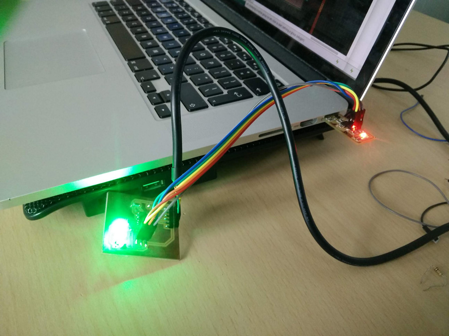
Update 19/06/2018: I returned to this weeks assignment after several months of learning on programming pcb boards.
I knew that I had to use the six pin headers to program a board with the USBtinyISP. I selected my output week board with the RGBLED.
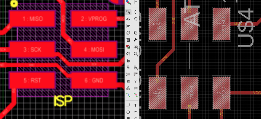
I compared the orientation from the tutorial image with my Output board in Eagle (board view). When the pins were connected, I plugged in the USBtinyISP and used Arduino IDE to upload the following code (a variation on my output week code - blinking LED).
int led_pin = 6;

void setup() {

  pinMode(led_pin, OUTPUT);
}

void loop() {
  digitalWrite(led_pin, LOW);
  delay(500);
  digitalWrite(led_pin, HIGH);
  delay(500);
}
The program failed to upload. But when I connected the FDTI from my output board to the second USB slot on the Mac, it uploaded successfully and the RGBLED blinked. This gave the board more power to make a connection. I had successfully programmed using the USBtinyISP!
Back to the top