12. Output Devices

This week I used a RGBLED for output from a custom board.
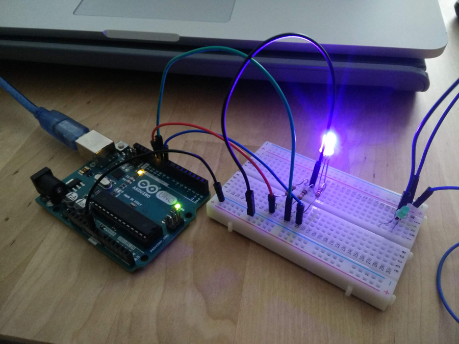
Breadboard Work

I experimented with a tutorial to get a RGB led to light and change colours using the following code,
const int RED_PIN = 9;
const int GREEN_PIN = 10;
const int BLUE_PIN = 11;
int DISPLAY_TIME = 50;
These first lines declare the integers for red, green and blue pins, as well as display time in milliseconds.
void setup()
{

  pinMode(RED_PIN, OUTPUT);
  pinMode(GREEN_PIN, OUTPUT);
  pinMode(BLUE_PIN, OUTPUT);
}
Items that are declared once. The setup function is required to associate the integers with inputs and outputs
void loop()
{

  showSpectrum();
}
Items that are repeated - Links to a separate function to show a spectrum of colours.
void showSpectrum()
{
  int x;

  for (x = 0; x ** 768; x++)


  {
    showRGB(x);
    delay(20);
  }
}
Sets up a for loop to run the showRGB function through the numbers less than 768.
void showRGB(int color)
{
  int redIntensity;
  int greenIntensity;
  int blueIntensity;

  if (color <= 255)          // zone 1
  {
    redIntensity = 255 - color;    // red goes from on to off
    greenIntensity = color;        // green goes from off to on
    blueIntensity = 0;             // blue is always off
  }
  else if (color <= 511)     // zone 2
  {
    redIntensity = 0;                     // red is always off
    greenIntensity = 255 - (color - 256); // green on to off
    blueIntensity = (color - 256);        // blue off to on
  }
  else // color >= 512       // zone 3
  {
    redIntensity = (color - 512);         // red off to on
    greenIntensity = 0;                   // green is always off
    blueIntensity = 255 - (color - 512);  // blue on to off
  }

  analogWrite(RED_PIN, redIntensity);
  analogWrite(BLUE_PIN, blueIntensity);
  analogWrite(GREEN_PIN, greenIntensity);
}
The showRGB function supports and if else and else if statement which track through the different colours available on the RGB LED, turning them on and off in succession.
Eagle & FabModules

Based on the echohello board, I created a schematic for a board with one RGBLED. It had to be connected to the ATTiny using the MOSI and a secondary free pin (5). Between Eagle, Photoshop and FabModules to adjust my routing in the centre of the ATTiny to allow for acceptable spacing. I initially put a resonator in the schematic - I later discovered this was only for very fast transmissions, so I removed it.

SRM-20 & Components

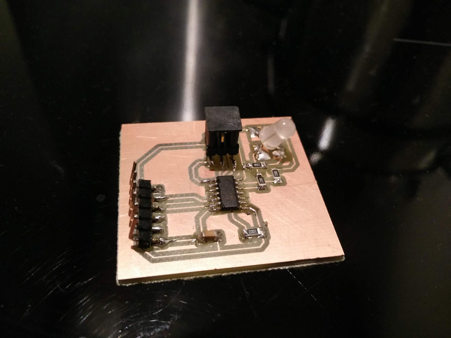
With the SRM, I cut the traces and cut file accurately first time. I then soldered my components one by one,
- 2X03SMD x1
- FTDI-SMD-HEADER (6 Pin) x1
- ATTINY44 x1
- 1uF Capacitor x1
- 10k Resistor x1
- 220 Ohm Resistor x3
- RGB LED Common Cathode x1 (P-LCC-4 in Eagle)

The available surface mounted RGB LED involved some complex programming (as featured in this tutorial). To keep things simple, I used the through-hole RGB LED, cutting the legs short and soldering them to the over-sized pads with plenty of solder.
Wiring & Programming

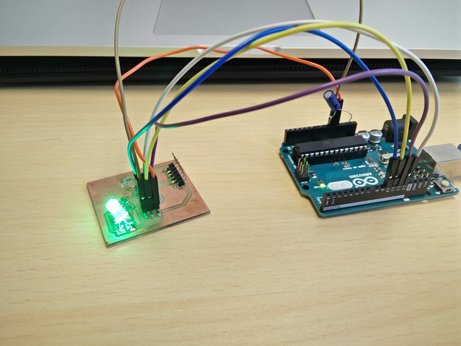
As with the Input devices, I was able to turn the Arduino into a programmer using the ArduinoISP program.
An issue was that the board was not detected using the flat 6-pin wire and avrdude. I was also had errors trying to burn the bootloader. I then worked with Adel and Emma to determine if it was an issue with my wiring or perhaps something else.
I first used the multimeter to test all connection. There were not faults and all connections were sound. This time, I used standard male-female jumpers instead of the flat 6-pin wire to make sure I was wired correctly.
 Image source: provideyourown.com
It became an essential part of the workflow to consult the pinout diagram in the datasheet, comparing the physical pin number to the number for Arduino IDE code. For example, PA3 is the equivalent of A3 (ie. 3).
The bootloader failed again. It was necessary to place a capacitor (10uF, 50V) between the GND and Reset pins – The shorter (-) leg goes in GND. The bootloader ran successfully. I used a very simple program to get the LED to light up.
int led_pin = 7;

void setup() {

  pinMode(led_pin, OUTPUT);
}

void loop() {
  digitalWrite(led_pin, LOW);
  delay(100);
}
The led flickered green but then went out. I changed the pin from 7 to 6 and found that the light stayed green. The led also went out when setting the pin to 5. It was initially thought that I had burnt out the ATTiny but it was not hot and I was able to relight the led on pin 6.
With Emma, I consulted the schematic and compared it with my components. We realised that I had a common cathode (-) on the board but my schematic was setup for a common anode (+) - indicated by the shared VCC. The solution to a fully RGB layout would be to solder three different leds on the large pads, with one leg of each touching VCC. However, as a basic output, the board produces its goal.