If it weren't for Fab Academy, in this period of my life (first half of 2016) I would be folding one thousand origami cranes. Instead, for my Final Project I plan to make "Thousand shades of crane", a zoetrope with 3d printed origami cranes, colour cycling through thousand shades of light: the digital equivalent of 1000 origami paper cranes for good luck and health. Whether or not this will work to be granted my wish by a crane depends on whether or not cranes have evolved since ancient Japanese times too.
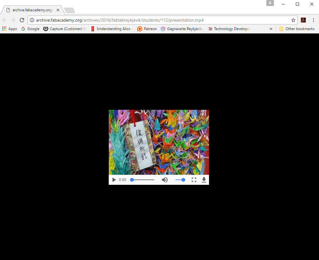
Thousand Origami Cranes (千羽鶴) is a group of one thousand origami paper cranes (折鶴) held together by strings. An ancient Japanese legend promises that anyone who folds a thousand origami cranes will be granted a wish - such as a long life or recovery from illness or injury - by a crane.
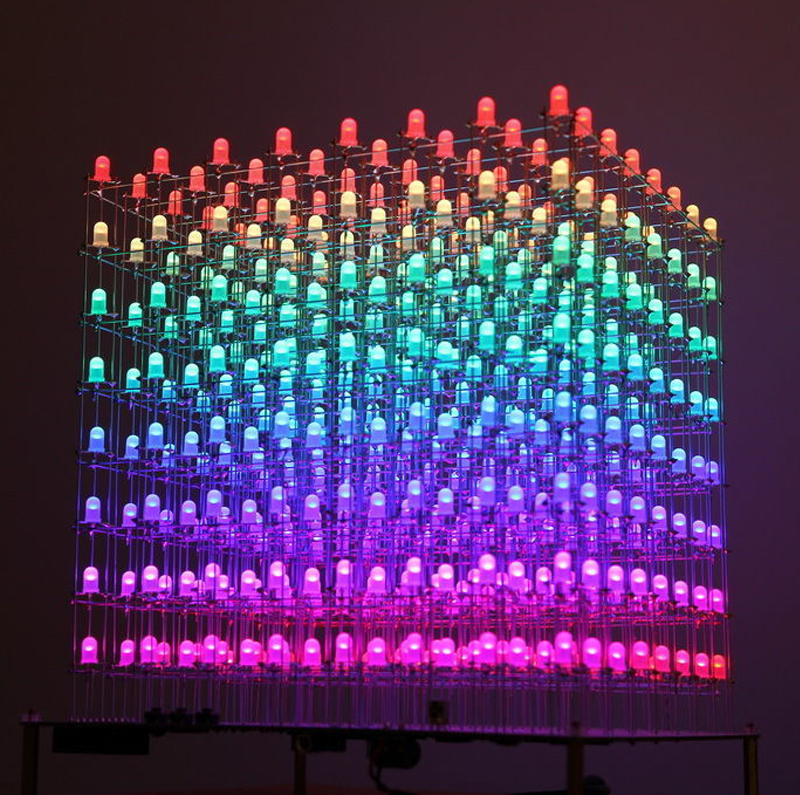
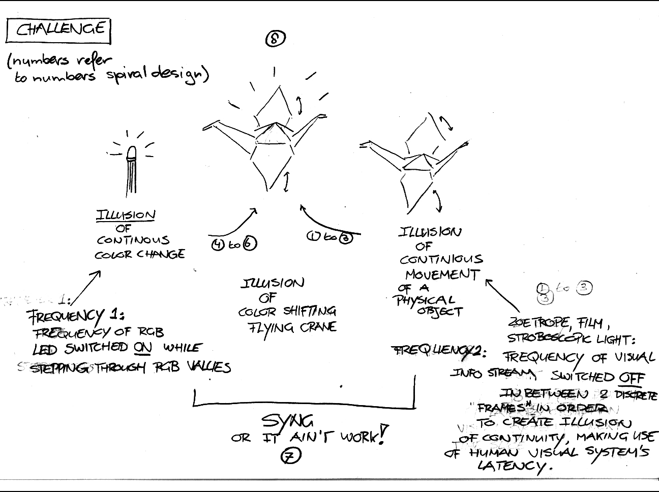
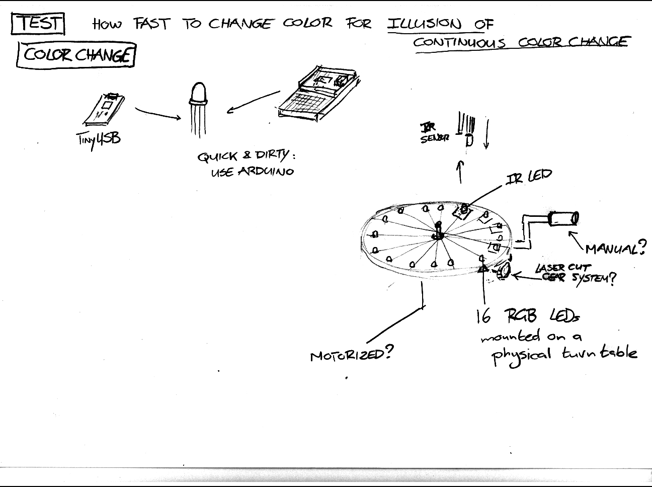
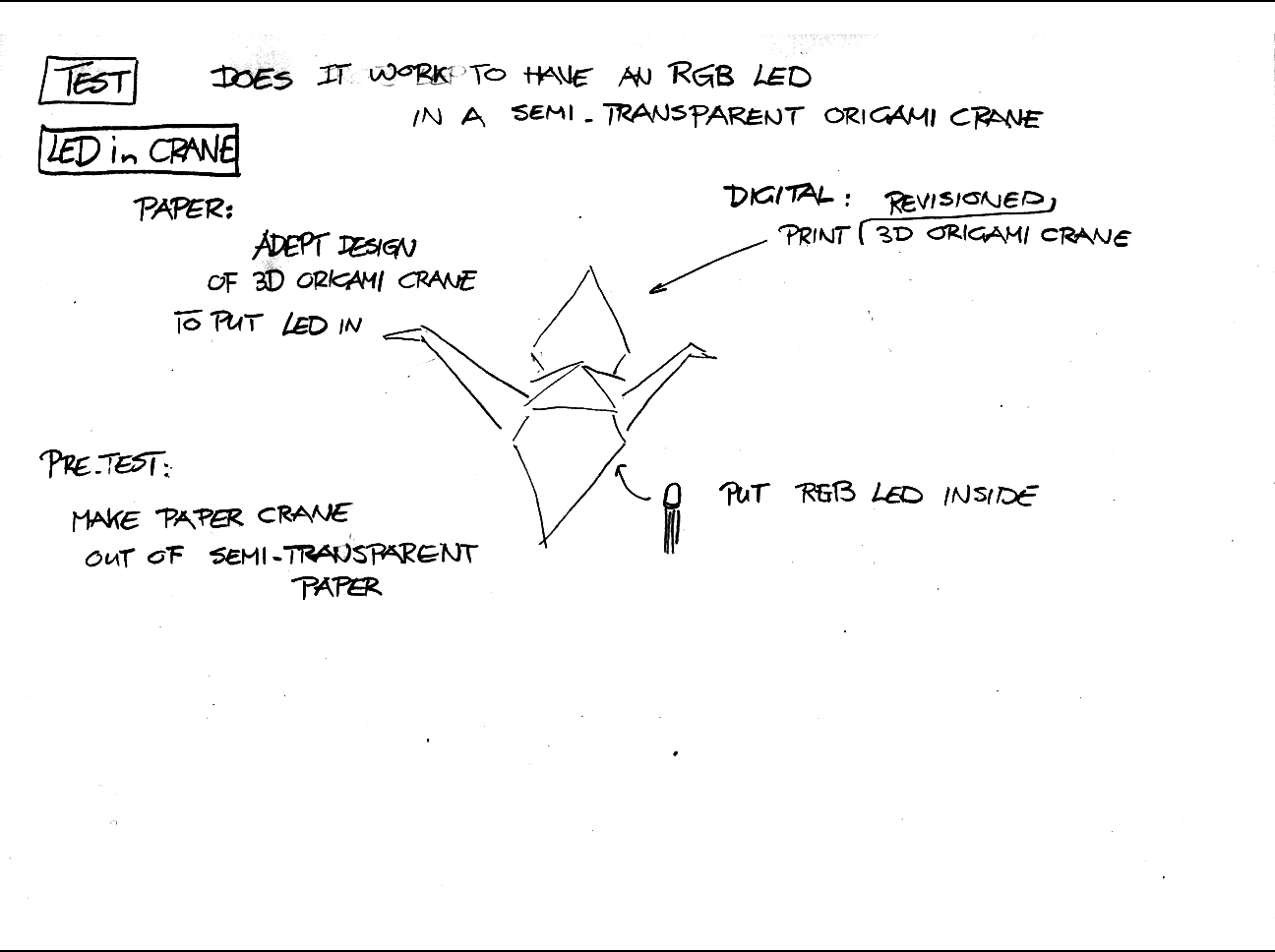
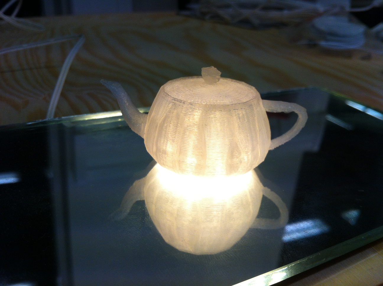
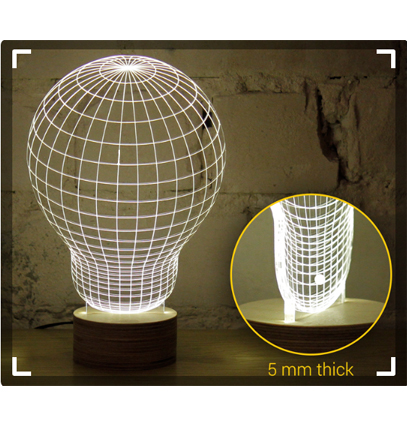
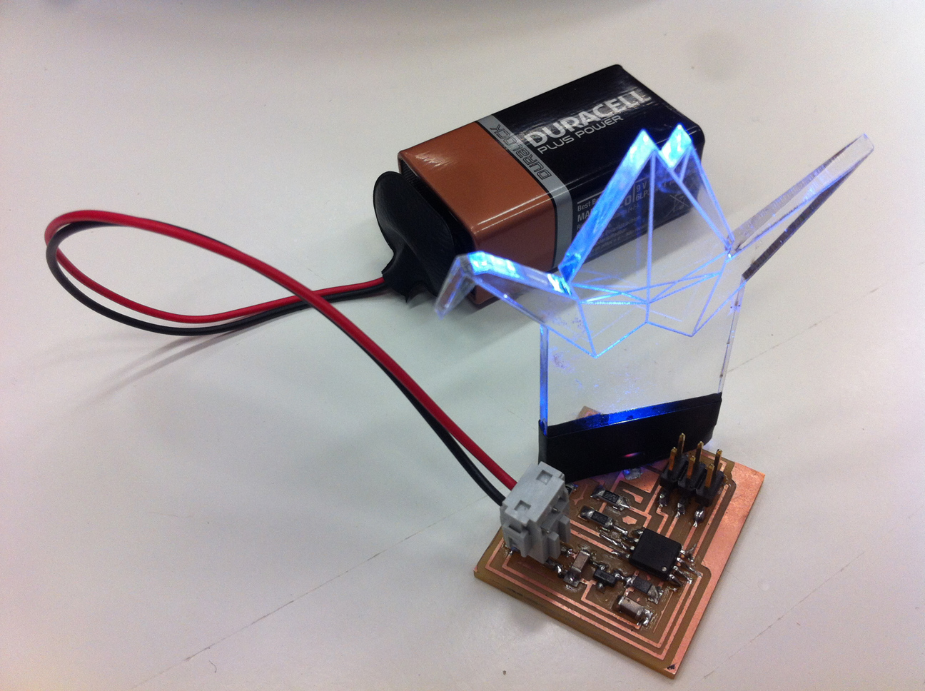
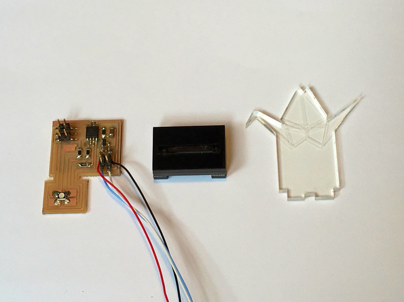
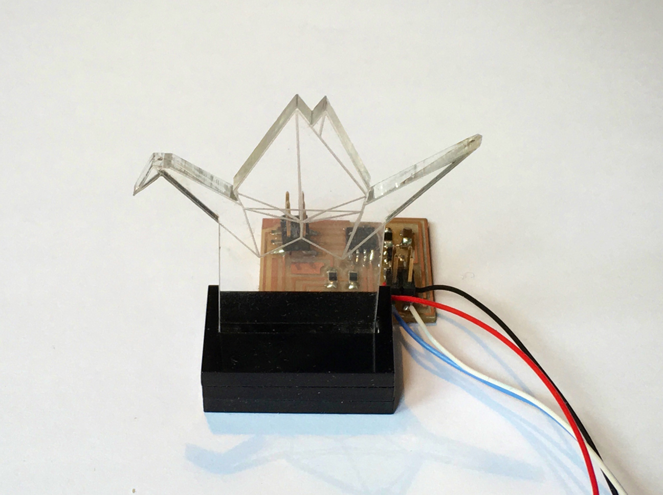
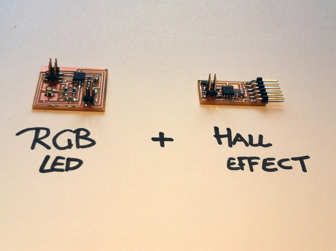
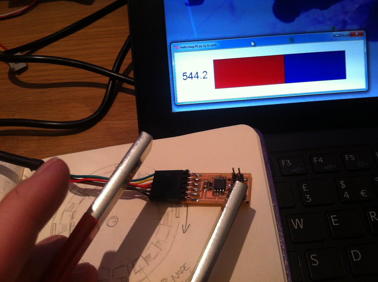
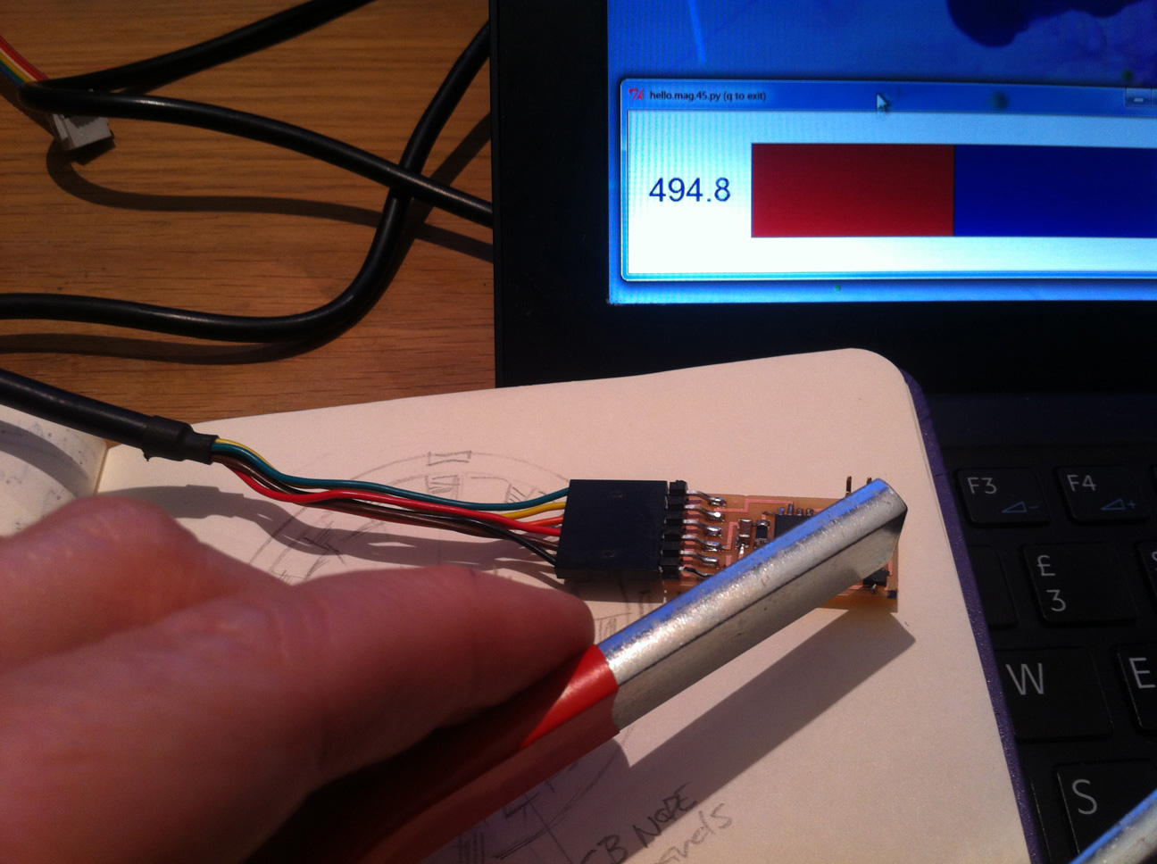
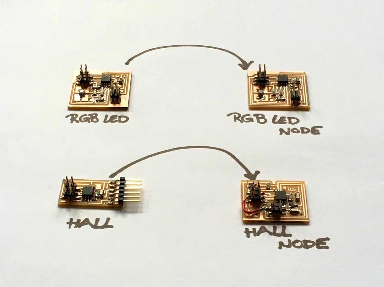
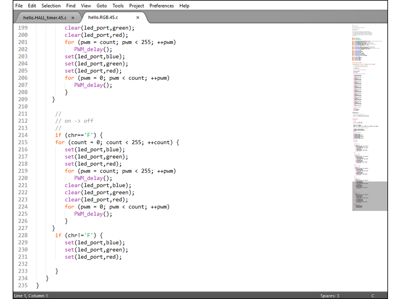
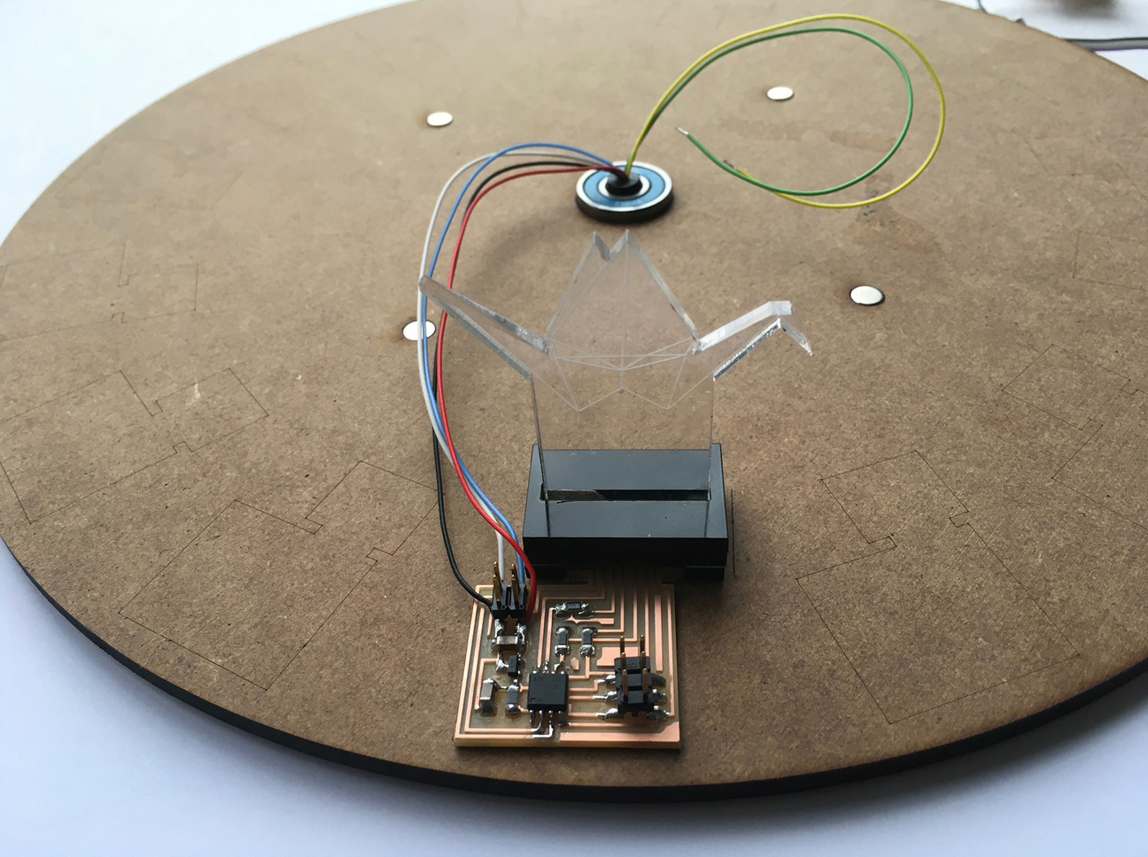
This is where the shades will come from: 16 ATtiny controlled RGB LEDs to display 1024 different colours. The RGB LEDs will be built insides semi-transparent 3D printed origami cranes.
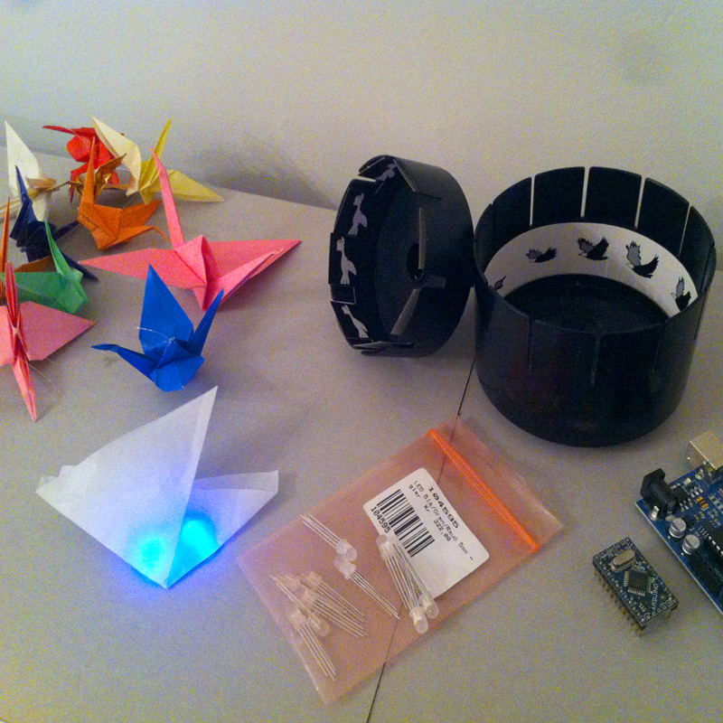
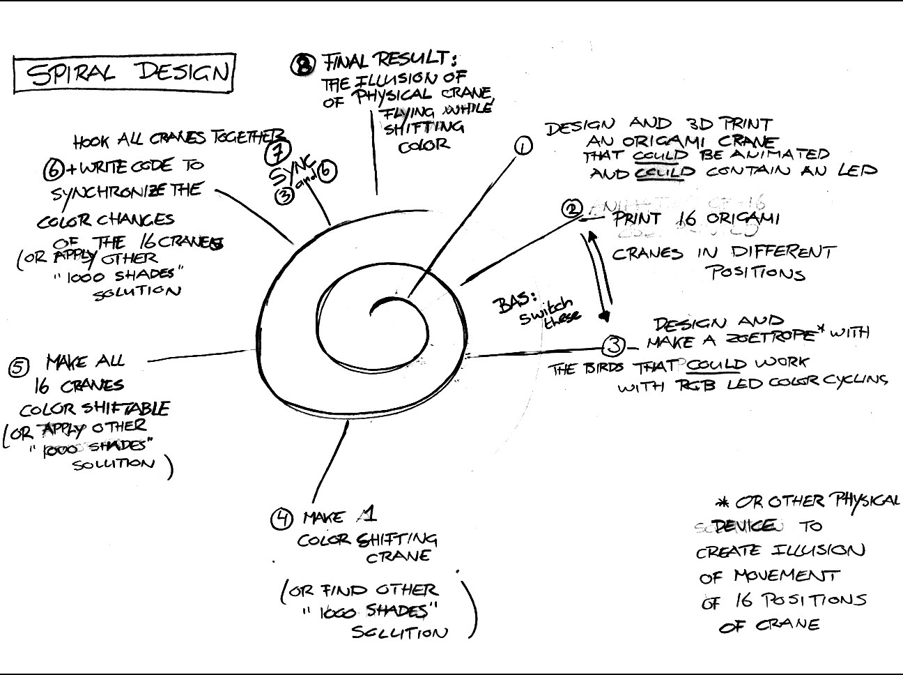
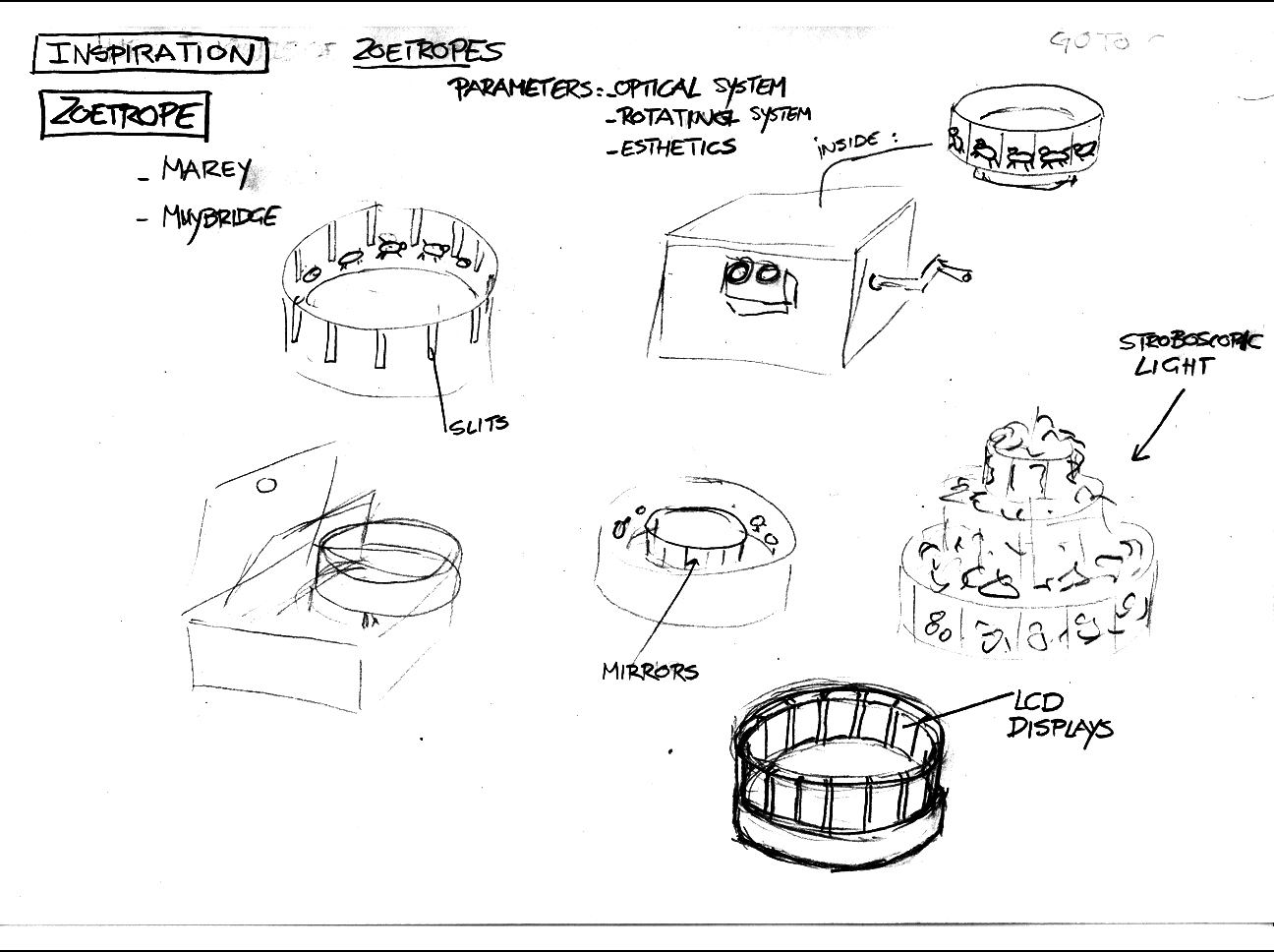
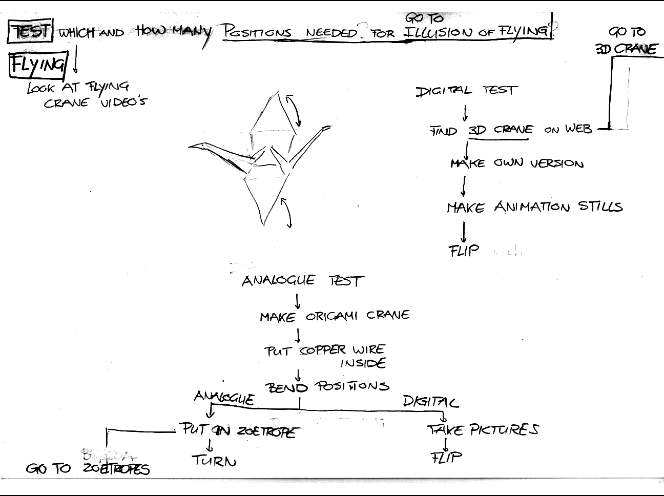
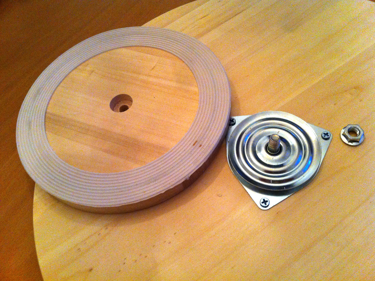
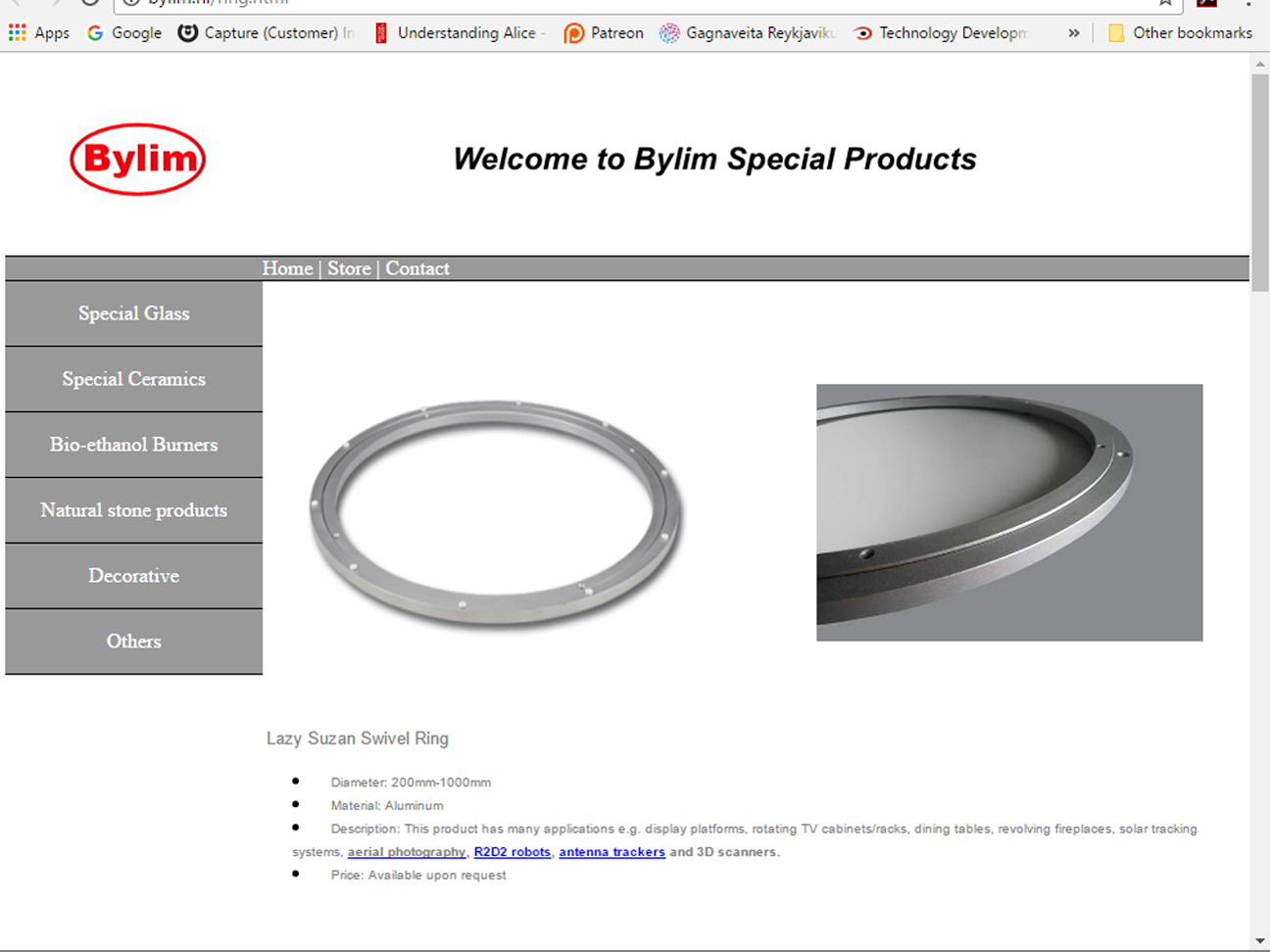
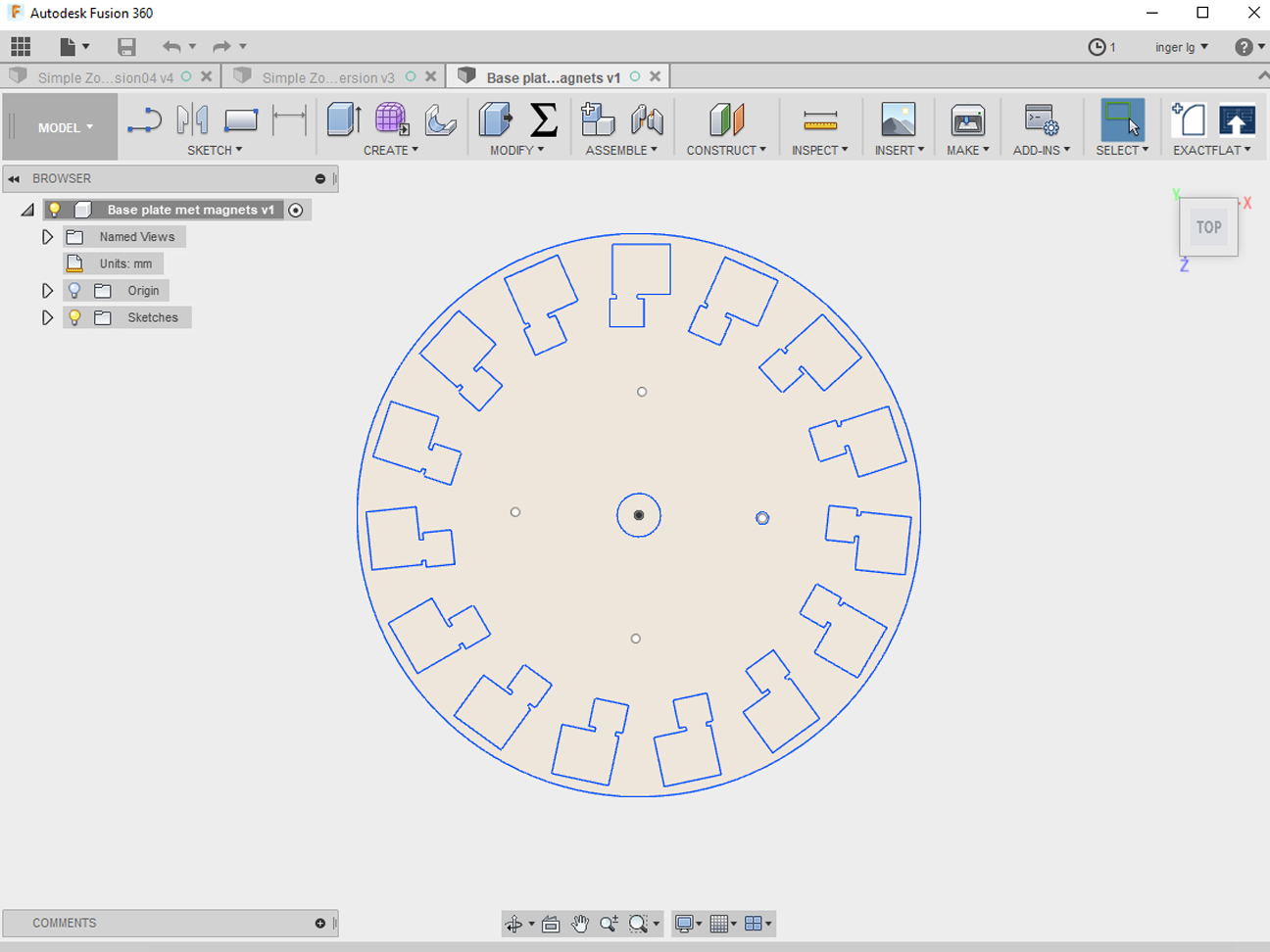
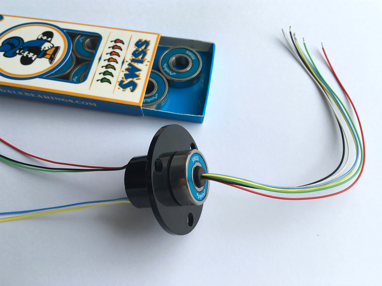
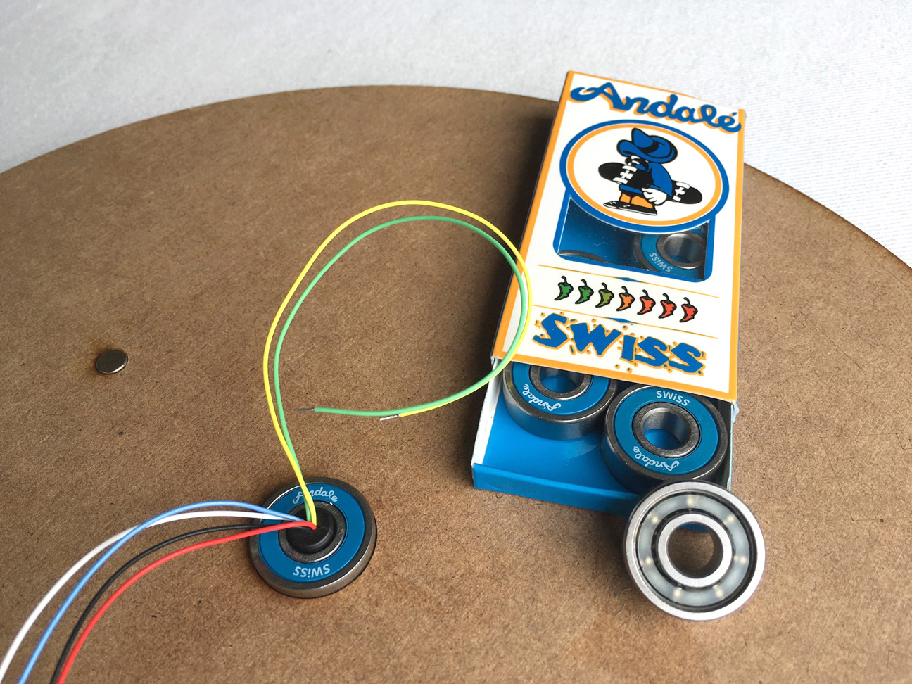
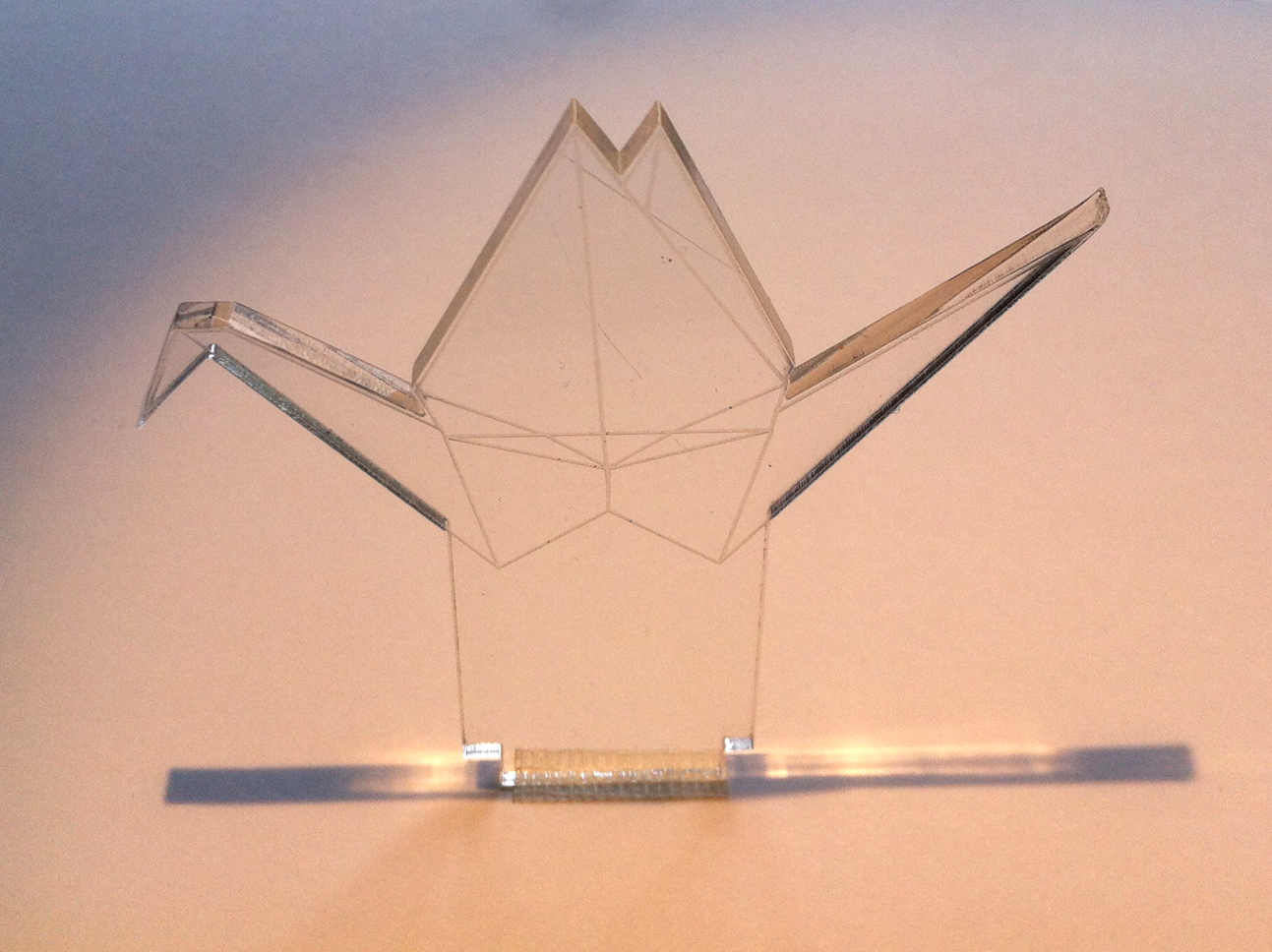
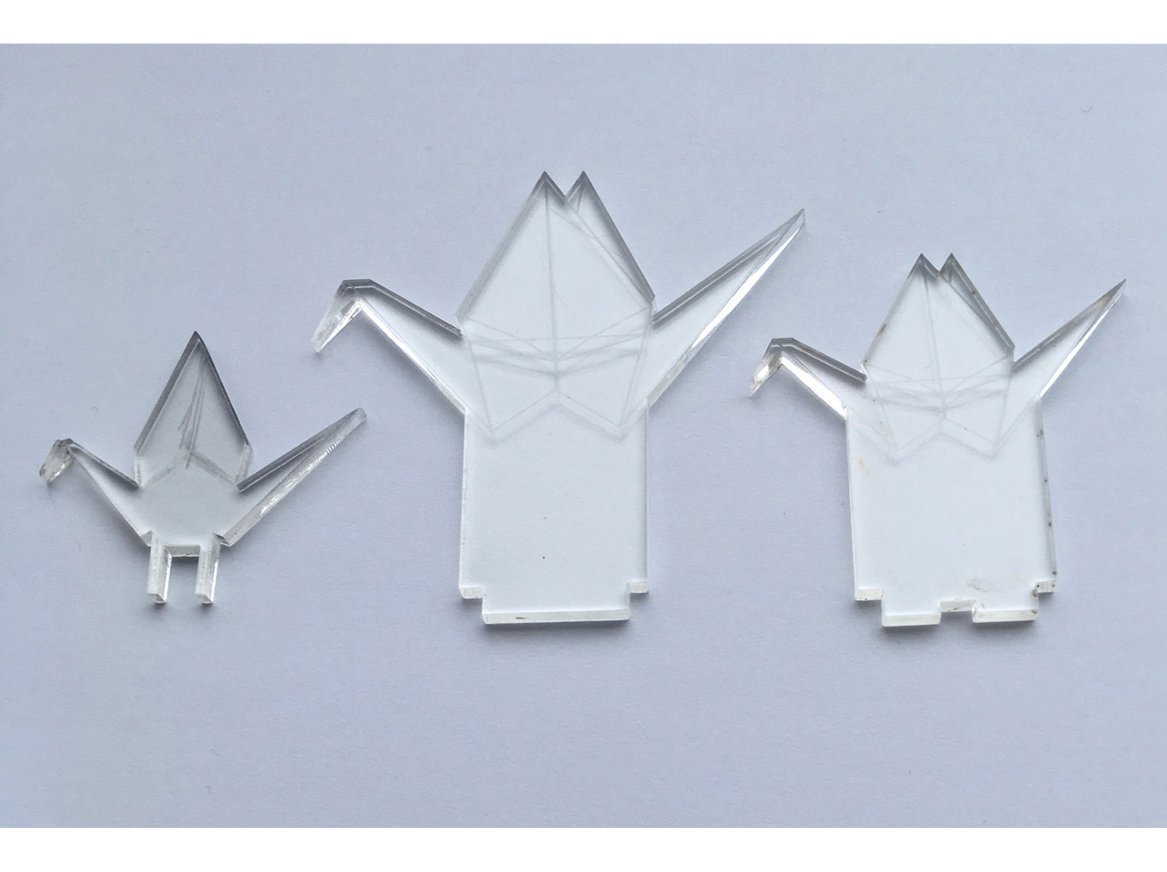
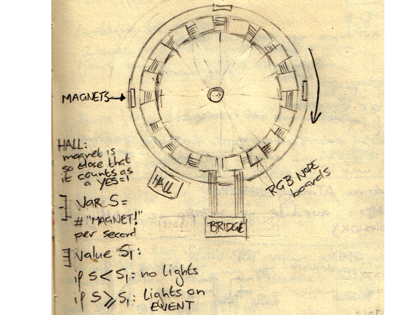
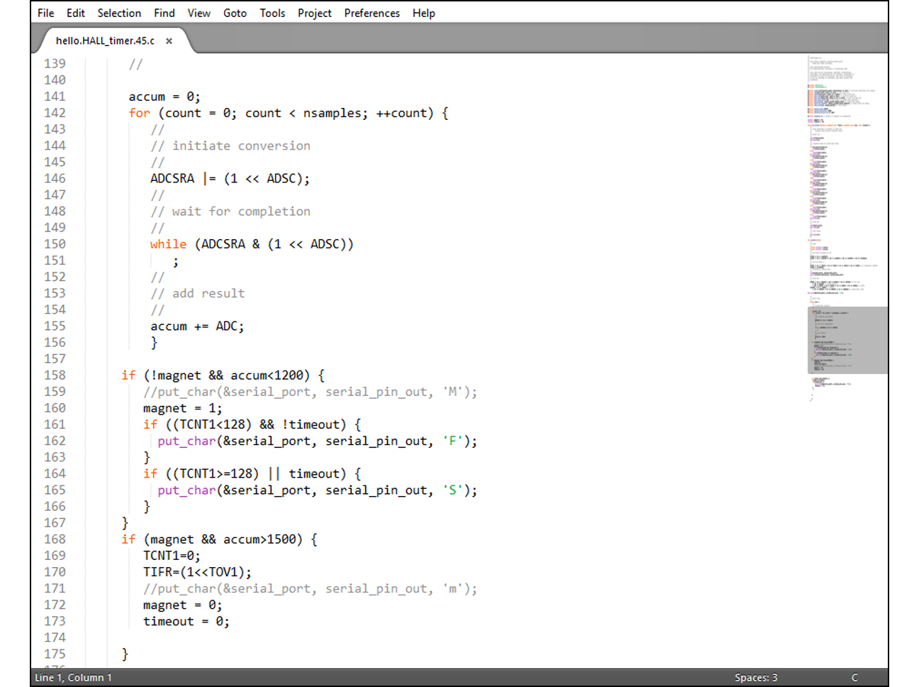
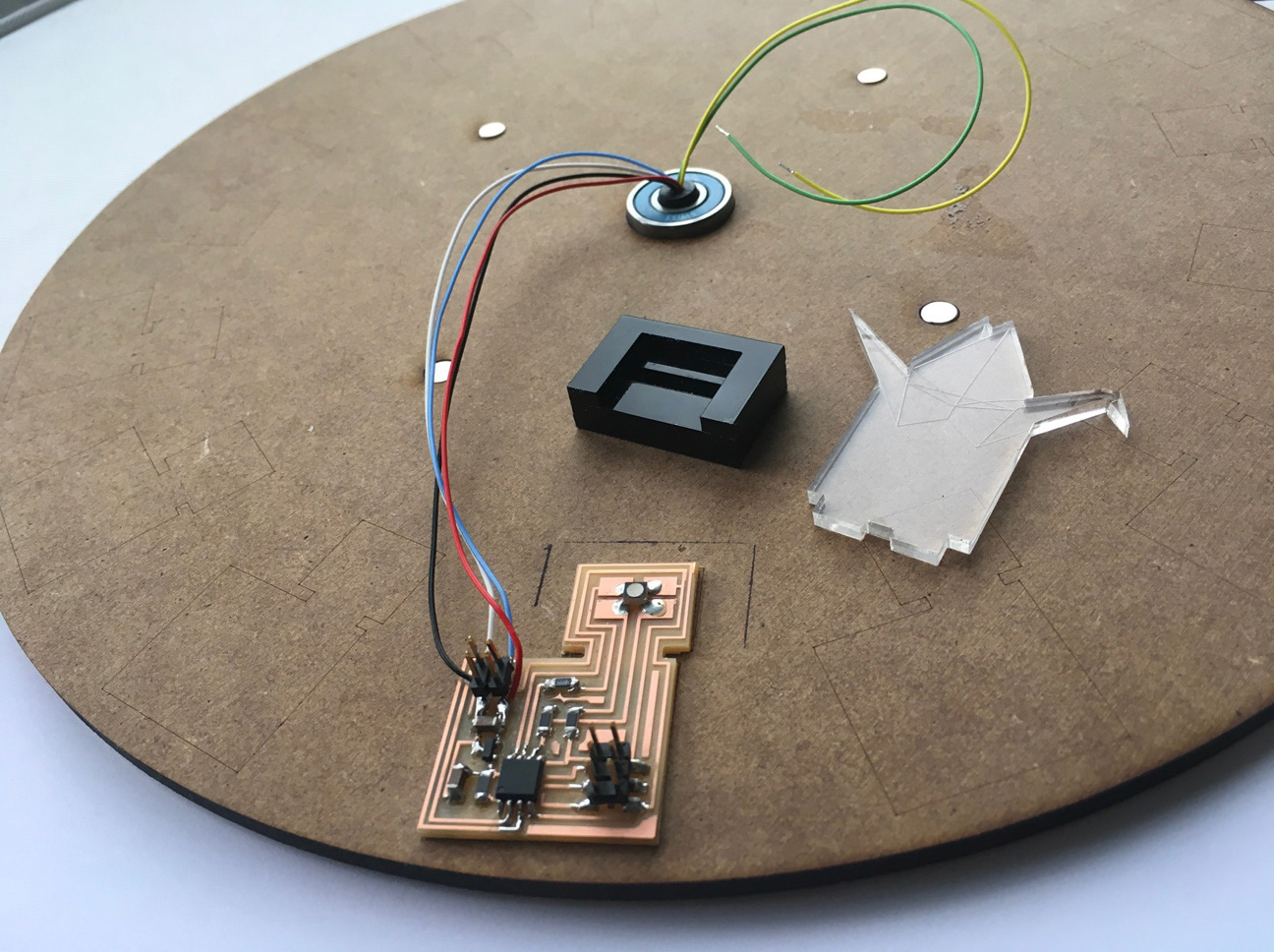
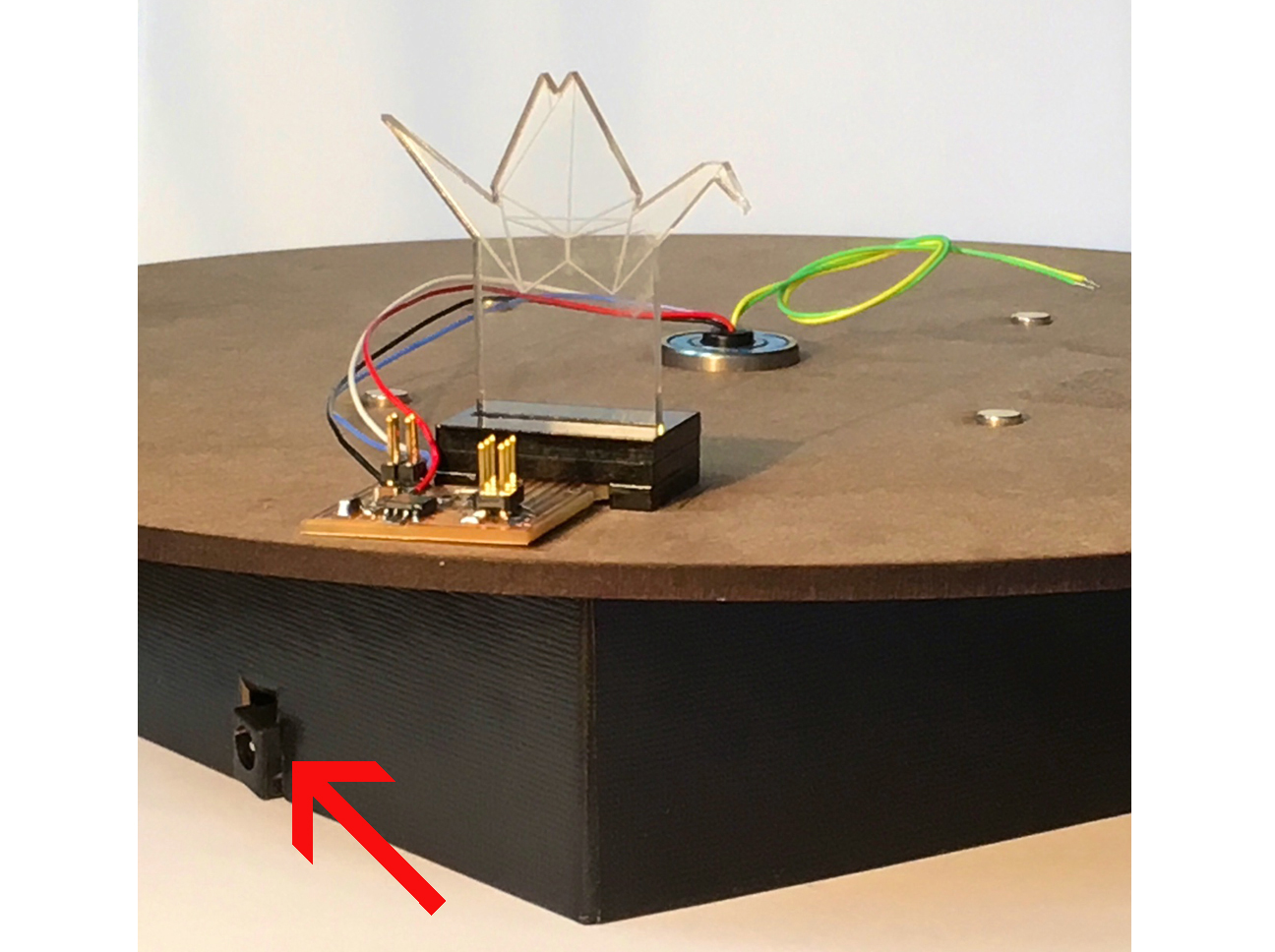
Twelve to sixteen 3D printed semi-transparant origami cranes, each in a slightly different flying position (like the frames of an animation), each containing a ATtiny controlled RGB LED, the cranes positioned on a classical zoetrope: when the turning speed of the zoetrope and the pulse width modulation of the LEDs are properly synchronized, will one really see a colour shifting flying crane?
Various types of zoetropes and comparable devices exists, all making use of the latency in the human visual system to create the illusion of movement. By presenting a series of static images, alternated with a status "no visual information", the human visual system perceives motion. In a classical zoetrope this alternation was created by the slits in the black cylinder. The nowadays popular 3D printed versions (like the famous All Things Fall) use stroboscopic light to trick the visual system.
Pulse width modulation is used with RGB LEDs to get mixed colors. The big challenge for the Wow version: how to sync the components involved in creating the illusion of continious color change (Frequency 1) and the ones involved in creating the illusion of continious movement (Frequency 2) in order to create the illusion of a color shifting flying crane.
What needs to be tested is how many wing positions are needed for the illusion of a contious flying movement. This can be tested digitally in an animation program. A quick & dirty first draft might be to photograph a paper bird with (copper wired) bendable wings and use a flip book app or to just draw the bird on a zoetrope strip and watch it in a zoetrope toy.
What has to be tested is whether or not it works to put an LED in a semi-transparent 3D printed crane. It might be that this is not a good idea at all and that the illusion of a color shifting origami crane bird can better be created by illuminating the bird form the outside or from the bottom. It might be needed to adapt the design of the bird then.
My Thousand Shades of Crane zoetrope consists basically of 4 elements: a Zoetrope Base, Crane Birds, the Electronics, and Look Through Slots to create the animation effect. Although I had to work on all 4 elements in parallel because of some interdependencies, for clarity the documentation below is divided into those 4 separate subjects.
I wanted the experience of "making the birds fly" and "make them change colors" to be intimate and direct. With this in mind I decided my zoetrope should be rather small (about 30-40 cm in diameter) and should be turned by hand to make it spin. I looked at things I could use as a starting point and found this Snudda Lazy Susan at IKEA.
Hacking this Snudda Lazy Susan I discovered something really important: because I would need to run wires from the bottom to the top side of the plate for power and data (see Electronics below), there should always be a hole in the middle to allow for this. IKEA's Snudda had a big bolt in the middle, so it did not meet this requirement.
On the web I found these Lazy Suzan Swivel Rings I thought I could use to make a lasercut or CNC-ed Lazy Suzan with a hole in the middle. The swivels not being for sale in Iceland (where I live), I ordered 2 sizes online. Once they arrived, it appeared to be very hard to turn them by hand and even impossible to make them spin, hence indeed fit for use in rotating TV cabinets - as stated in the description - but not for a smooth spinning zoetrope.
Living in Iceland means: never knowing if/ when orders from the mainland will be delivered. Because of this and while waiting for the swivels to arrive, in parallel I looked into DIY possibilities. I found this flat wood thrust bearing (similar to a lazy susan) using marbles and lasercut plates and spacers. It looked promising, until for this design to work properly the importance of using equal-sized marbles was emphasized.
Unfortunately the only marbles on stock in Iceland were these ones from Toys 'R Us, not equal-sized at all! Since I couldn't find any other balls I could use (no steel balls found and 3D printing was not an option because the balls needed to be perfectly round and smooth), this solution was a dead end too.
Meanwhile I had contacted Quinten Zwagerman from The Netherlands who made this Pristitrope, asking him for advise. For the turning mechanism he initially used this type of lazy susan ball bearing, "for sale at any home improvement store". After half a day of driving through the country I know now: this might be true in The Netherlands, but certainly not in Iceland!
In his second model Quinten used this construction and the commercially available ball bearing he is showing in the picture. Unfortunately and again: not for sale in Iceland. The ball bearings that were in stock in Iceland, were the ones used in industrial machinery, trucks and glacier-proof 4wheel drives. Far too heavy to be turned by hand, so no option for my zoetrope.
By the time I was getting desperate, the Slip Ring with Flange I ordered from the UK (see Electronics below) arrived. The design inspired me to try this: would it be possible to pressfit the bottom ring in a box and the top ring in a light zoetrope base plate, hence using the slip ring itself as the turning mechanism for the zoetrope?
To test this I cut a hole in a carton board box and lasercut an MDF base plate that I designed in Fusion 360. (Fusion 360 - Inkscape - Acrobat workflow described week 4). It worked! It was possible to turn the base plate by hand and it keeped spinning smoothly (although wobbely) for quite a while after each turn.
The design of the base plate itself evolved overtime to this final version, including small holes for magnets and engraved contour lines for the RGB LED printed circuit boards (see Electronics below).
In the middle of the base plate's final design is a larger hole to fit in a skateboard ball bearing, as per the suggestion of our lab's instructor/ guru added to the construction to avoid damage to the plastic of the slip ring. After all "not available in Iceland" experiences I was really surprised these ball bearings were for sale and on stock in a skate store just around the corner. I was even more surprised when the ball bearings appeared to have exacly the right size to be pressfitted on top of the slip ring.
Next step was to fold a crane bird out of semi-transparent paper en put it on top of the RGB LED board I made for the OUTPUT assignment in Week 13. This RGB LED in Crane Bird test looked less promising: no light went into the wings of the bird. Since getting the illusion of a flying bird heavily depends on seeing different wing position, this was quite a big problem.
Since my initial plan was to make 3D printed birds, first thing to check now was how LED light spreads in small semi-transparent 3D printed objects. There was a teapot lit from below by an LED in the FabLab and here too I could see the light did not spread very well through the whole object.
I changed the geometry of the stands and tested several possibilities for putting acrylic birds on top of the RGB LED board. The one at the right gave a very nice result, as can be seen in this video clip.
What can be seen in the video too was the importance of blocking off the sight on the LED itself to have the "magic" effect of the engraved traces lighting up and the light escaping from the borders. To see the difference I wrapped a piece of black tape around the bottom of the acrylic bird. It made a huge difference not to be blinded by the LED itself.
I designed a small black box to put on top on the RGB LED with a slot in the middle to put the foot of the bird in. The box consisted of 3 layers of acrylic glued together by double sided tape.
As can be seen already in the previous picture, I changed the design of the RGB LED board so that the RGB LED would be exacly in the middle of the crane bord and the whole unit could be press fitted together. (The soldered wires are the very quick & dirty solutions for not having thought over well enough how to power the birds once they would be glued to the base plate of the Zoetrope and were to be powered through the wires of the slip ring).
Initially I made the black boxes out of shiny black acrylic plate. This looked really good, but press fitting an acrylic bird in an acrylic slot does not work very well. Also: I forgot to have an additive component in my Final Project, so as a solution for both issues I re-designed the black box as a 3D object in Fusion 360 and exported it as an .stl file to be 3D printed.
The basic idea for the electronics part was: use a Hall effect board (= INPUT) to deduct the spinning speed of the hand-turned zoetrope from the number of times a magnet passes the sensor per time unit and when the spinning speeds exceeds a predefined number: switch on an RGB LED (= OUTPUT) and make it colour cycle through the colour spectrum.
In Week 11: Input Devices I made a Synchronous Detection board because I planned to use this as an input device. I changed this plan because of to expected latencies and problems that would arrise from that. Using a Hall effect board and 4 magnets spread evenly around the circular base plate of my zoetrope seemed to be a better solution. I designed and made the board, programmed it and used the python script for Hall boards to see the difference between holding one pole of a magnet close to the board .... .
After what I learned in Week 15: Embedded Networking and Communication, hooking up the boards was "business as usual", although for programming the boards the assistance of our local instructor Bas was indispensable. In this setup a bridge board was still used. Later, when it became clear I was running out of time and would not be able to make more than one bird unit, the bridge board was skipped and the RGB LED board was listening directly to the Hall board.
One of the resons I was running out of time was the shortage of sharp tools in our Fab Lab, resulting in bad milled boards like this. Only one Modela being available for milling good boards in the days just before Presentation of Final Projects and six Fab Academy students still needing to mill their Final Project boards does not help to speed up production.
In top view and layed out flat, this is what my networked Hall - RGB LED network looked like. Power was supplied by a 12 Volt DC power supply. A slip ring was used for wiring the RGB LED node on top op the zoetrope's base plate, allowing the base plate to rotate without entangling the wires.
The counter part of that piece of Hall board code can be seen in this part of the code for the RGB LED board. The code shows the instruction for what to do when an 'F' character is received from the Hall board, being: switch on the RGB LED and colour cycle throught the colour spectrum as long as the predefined minimal rotating speed is preserved.
Once everything was "just in time" ready to be put in place, I discovered I didn't think of how to connect the RGB LED board on top of base plate to the network cable with the Hall board glued the other side of the base plate attached to it. I was saved by our local instructor who showed up really "just in time" with a soldering iron and soldering wire to allow for this last minute fix.
After putting everything together this is what my zoetrope looks like from above. Most remarkable details: due to lack of time only one crane bird instead of fifteen and because of that no need for an outside wall and see-through slots. Would I have had more time, I would have add 14 birds. On the other hand: creating the illusion of continuous movement of a real-world birdy has been done already by Marey in 1887 and by many, many others since then. On the other hand: making a bird shift colors driven by the rotational speed of the hand-spun circular plate it stands on, hence creating the illusion of continuous colour change through the spectrum, is a trick I have not seen done before. It is for this reason I myself consider my Final Project to be succesfull ...
... even though there are some other details (not visible when looking at the zoetrope from above) that could have been taken care of would I have had more time. Then again: none of these are visible when looking at the beautiful continuous change of colour of an acrylic crane bird!
Twenty weeks and a full cycle of Fab Academy later this is how I presented my "Thousand Shades of Cranes" final project. In the sections above, separate parts of the design and fabrication process were described. Answering the question whether or not making this digital equivalent is a viable alternative to folding 1000 origami cranes, falls beyond the scope of this documentation and will be discussed at a different time and a different place in the cloud.
A few days after I presented my Final Project, this zoetrope by Akinoro Goto went viral. It is so innovative and beautiful I thought it really should be added to this page.
As a 2016 Reykjavik student I presented my Final Project June 2016. Overtime the requirements for Final Projects have changed, for instance: wires should be properly encased now and not just dangle loose as obviously was the case when I presented my results. Meanwhile my live has also changed: to get additional rehabilitation therapy for my husband (the "beloved one" I made my Thousand Shades of Crane for) we moved to The Netherlands. Here, at Fablab Amsterdam, a few weeks ago and in the context of MakeHealth:prototyping I pitched a project that has been chosen amongst 5 others to be prototyped by a team of "citizens, caregivers and makers" in a period of 8 weeks time. My team is working on a solution for people with acquired brain damage (like my husband) who have lost their sense of time and need a kind of "metronome" as a cognitive prosthetic to keep them in a daily rythm. As stated in week 18: my Final Project can not be disseminated. What is disseminated though is the knowledge and skills I got by doing Fab Academy. It is one thing to make the digital equivalent of folding 1000 origami cranes and wish for health and recovery for a beloved one, but another to be able to make a tool that actual contributes to that health and recovery of your beloved one. I will continue to post links to future projects here.