Input Devices
Description
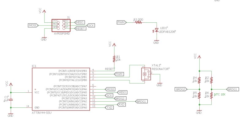
For the Input Devices assignment, I used a 10K NTC thermistor (NHQ103B375T10) to measure ambient temperature. The thermistor is part of a bridge circuit. According to the ATtiny44 data sheet it has 8 single ended analogue to digital converter (ADC) inputs. I used two of these inputs to measure the thermistor bridge voltage and convert it to a digital number that indicated the thermistor temperature. Referring to the schematic, each side of the bridge goes to a different pin of the ATtiny44. These two inputs are configured as analogue to digital converters(ADC). Within the program code the ATtiny44 ADC's convert the input voltage to digital numbers which are then subtracted from each other to give the voltage difference from which the temperature can be calculated.
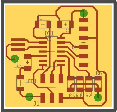
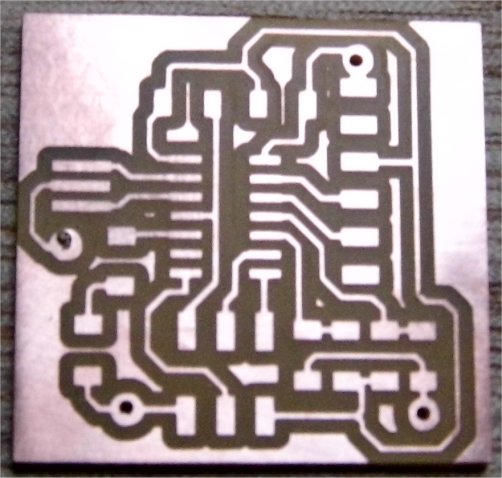
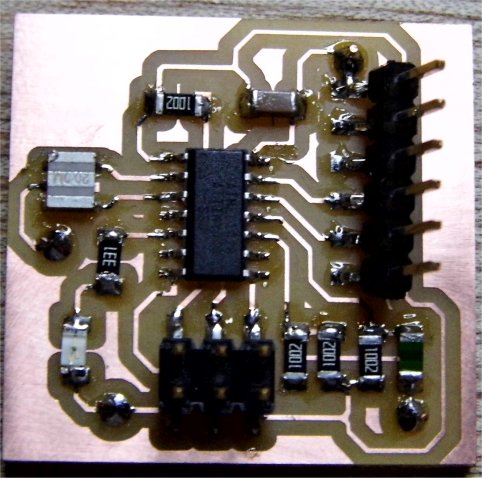
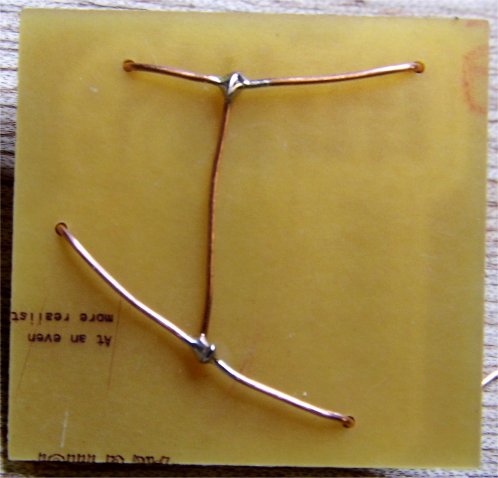
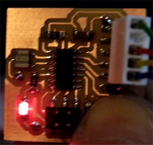
The circuit board was laid out in Eagle PCB editor. Some images of the CAD and hardware are shown below. This was constructed as a 1.5 layer board in that the bottom layer was configured as a ground plane but not actually routed as such. Instead any connections to ground were linked together via copper wire. The pcb was routed out on the Modela MDX20 using the Fab Modules. This process has been previously described here.
The thermistor's resistance decreases with an increase in temperature. From the schematic it can be seen that the voltage across the thermistor falls as the temperature rises. This voltage is fed into ADC input A2 of the ATtiny44 where it is converted into a 10 bit number (0 to 1023) where 0 represents zero volts and 1023 the ADC reference voltage which in this case is 5V. A thermistor's resistance changes according to the following equation:
Thermistor resistance = R0e^-B((1/T0) -(1/T))
where R0 is the resistance at 25C and B is the material constant that determines the resistance/temperature profile.
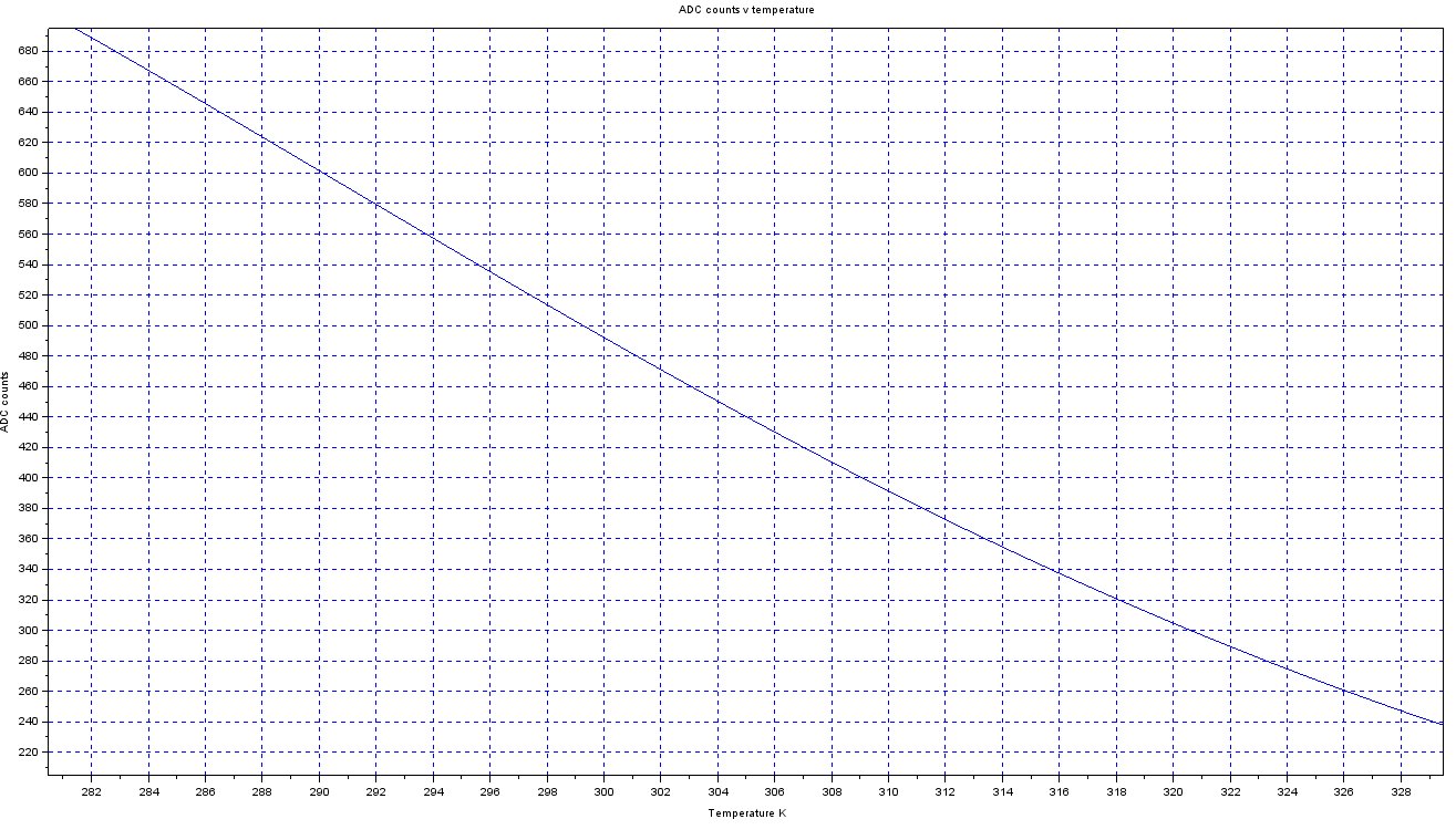
I created a script in Scilab which allowed me to plot the ATtiny44 ADC counts against temperature and used this to determine if my circuit was working. The graph below illustrates the plot results.
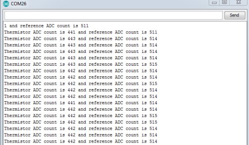
An Arduino program was written that sent the Thermistor ADC value -BRDG1 in the schematic - and the ADC value of BRDG2 - the other side of the bridge circuit - via RS232 to the PC where the values could be checked. I heated up the thermistor to hand temperature and noted that the ADC counts reduced and the count value reflected the measured temperature of approximately 32C.
New Arduino code was written that compared the two sides of the bridge circuit and if the voltage difference was greater that a set value then the LED would turn on. The count difference was also sent over RS232 to the computer which will help when debugging. This simultes something I wish to put into my final project where fans will only turn on if the temperature is above a set value.
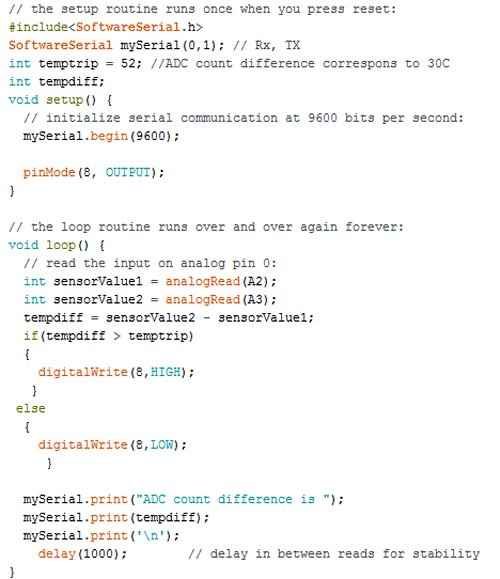
The code was tested by monitoring the counts as sent over the RS232 link to the PC and noting that the LED turned on when the count difference exceeded the threshold value.
Conclusion
The main thing I noticed from doing this assignment had to do with writing code for the ATtiny44 within the Aduino IDE. Adding the SoftwareSerial library and serial functions to the code pushed the compiled code to 3278 bytes, close to the maximum of 4096 bytes. For any future projects involving serial communications I will look at writing the code within another development environment or stick with the Arduino IDE but use a processor with more memory.
Downloads
- Eagle Cad files
- Modela manufacturing files
- Scilab thermistor script
- Arduino serial code
- Arduino temp trip code