Assignment 7: Electronics design
Redraw the echo hello-world board,
add (at least) a button and LED (with current-limiting resistor)
Learning outcomes:
-
Select and use software for circuit board design
-
Demonstrate workflows used in circuit board design
Group assignment:
-
Use the test equipment in your lab to observe the operation of a microcontroller circuit board (in minimum, check operating voltage on the board with multimeter or voltmeter and use oscilloscope to check noise of operating voltage and interpret a data signal)
-
Document your work to the group work page and reflect on your individual page what you learned
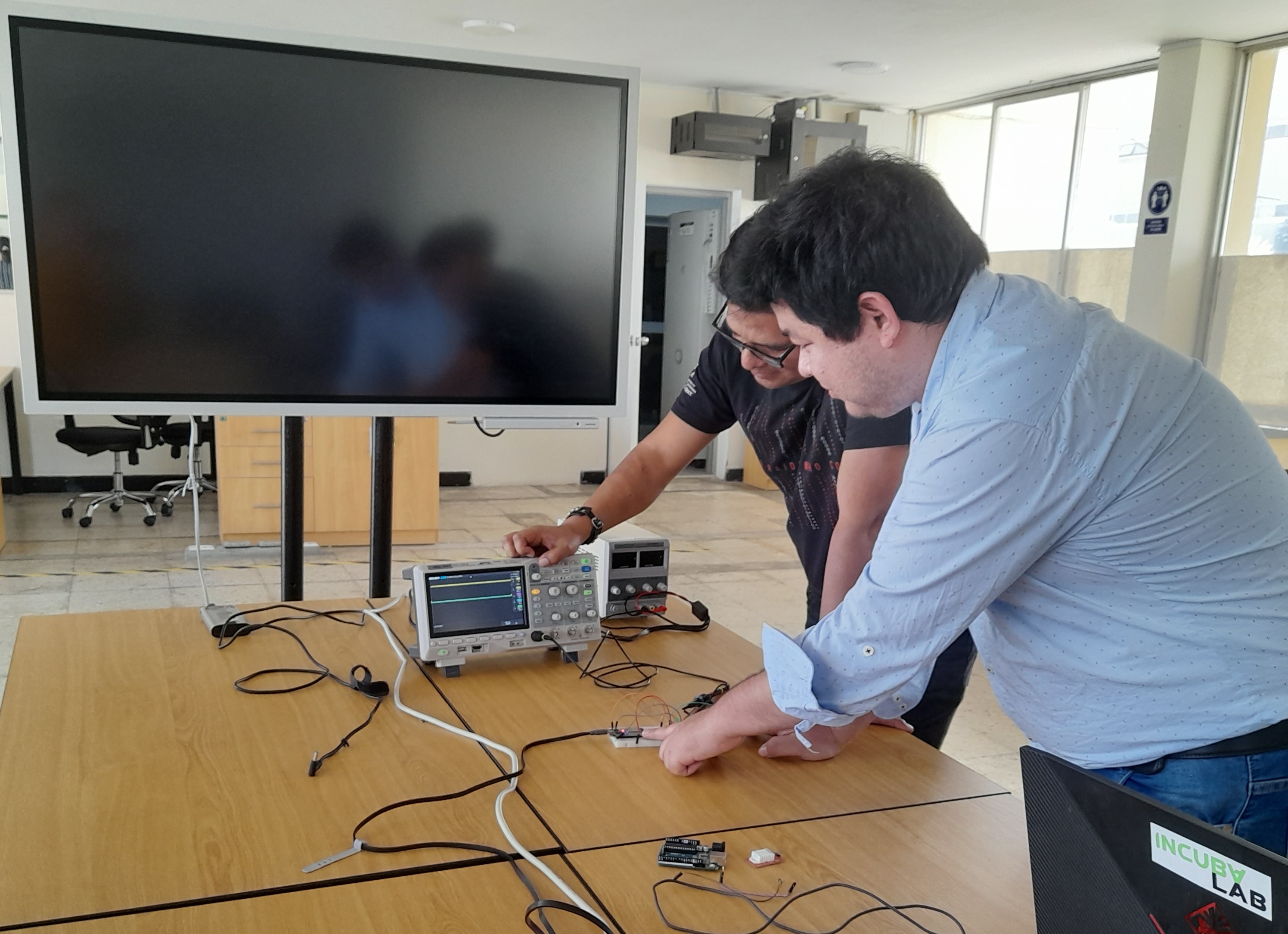
For this group assignment we tested the following equipment: oscilloscope and multimeter.
-
Oscilloscope
The oscilloscope is a device used to record oscillations of waves and presents them on a screen. The oscilloscope allows you to visualize the shape of a sound wave.
The main purpose of the oscilloscope is to measure and display voltage as a function of time. They are widely used for electrical/electronic design, testing, and debugging of almost any electrically powered device.
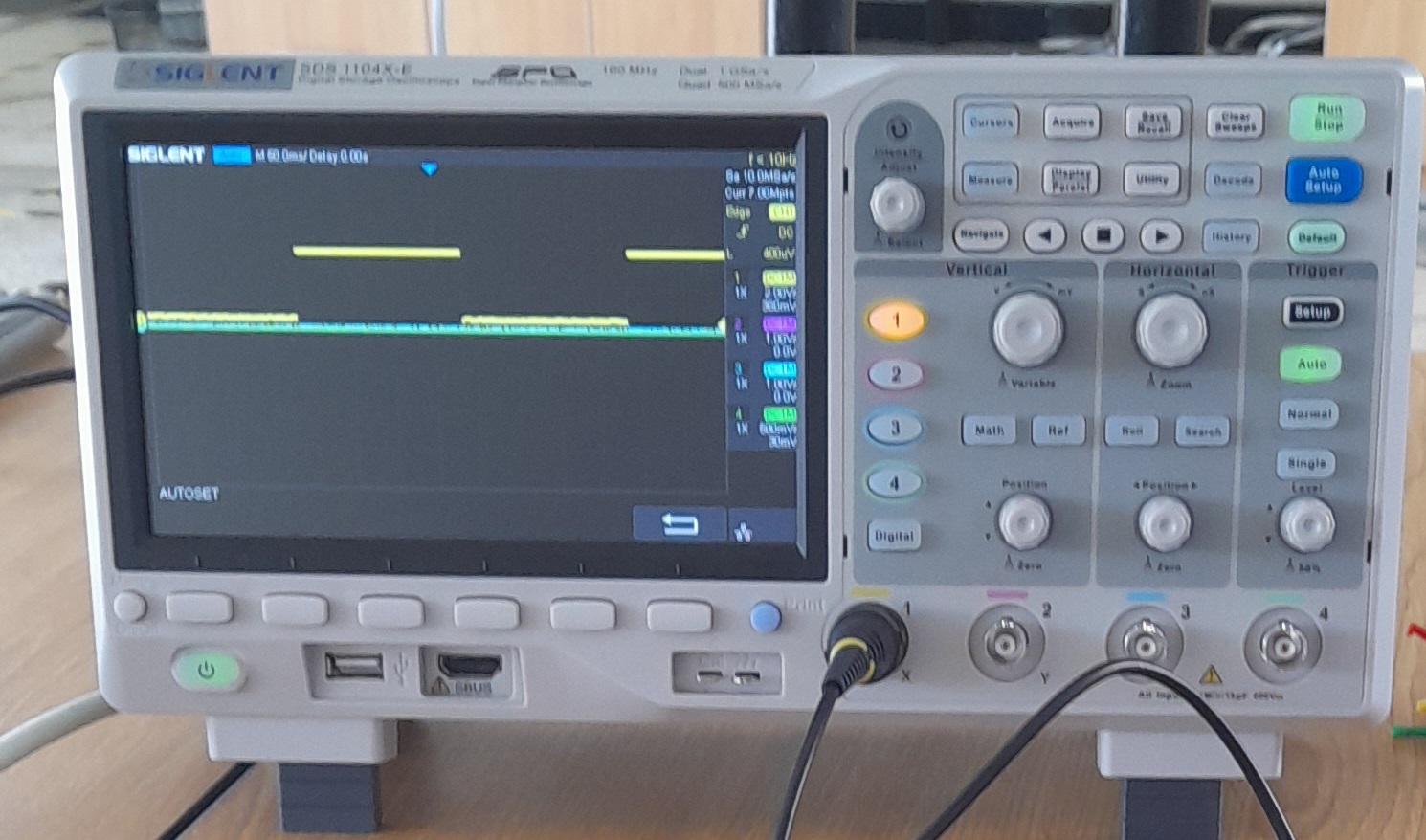
The oscilloscope model we use is the SDS 1104 X-E. It is a 4-channel digital phosphor oscilloscope with 100 MHz bandwidth, 1 GSa/s real-time sampling rate, 14 MB memory, oscillogram capture speed up to 400,000 osc/sec and 7.0" TFT LCD screen.
-
Oscilloscope test.
To understand how the oscilloscope works it was necessary to review the oscilloscope user manual.
The oscilloscope is a device that allows you to measure the electricity contained in electrical circuits. The measurement is made considering mainly two variables:voltaje and time.
Voltage: It is the force with which electricity is moving, depending on the circuit it can have different values, in the case of the circuit in which the measurement was made, there are resistors and devices that can make consumption.
Time: the time in the oscilloscope can be observed in values of milliseconds.
In the scilloscope we can see the electrical behavior of devices and circuits in their different phases of operation. The electrical behavior of devices can be displayed in different ways:
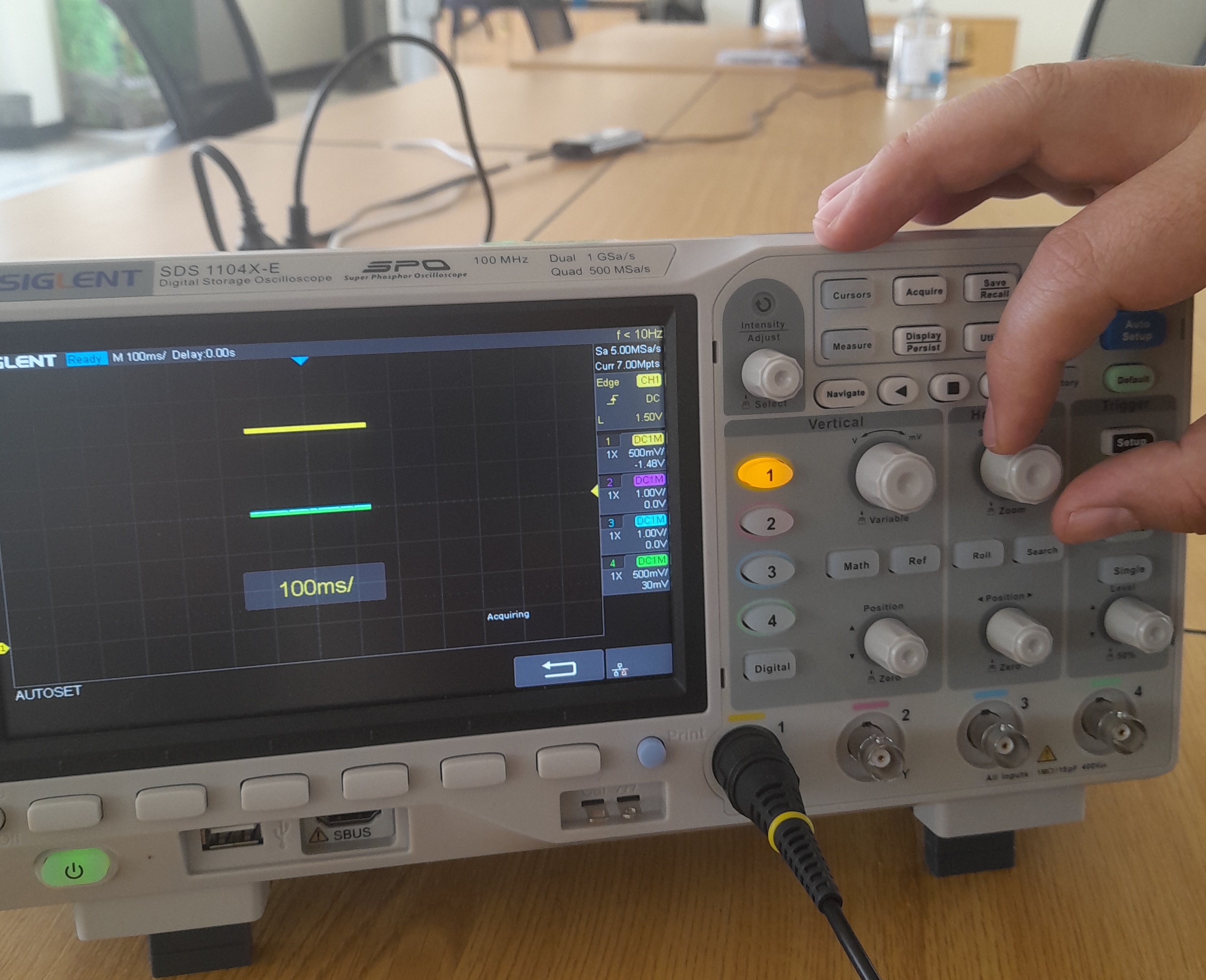
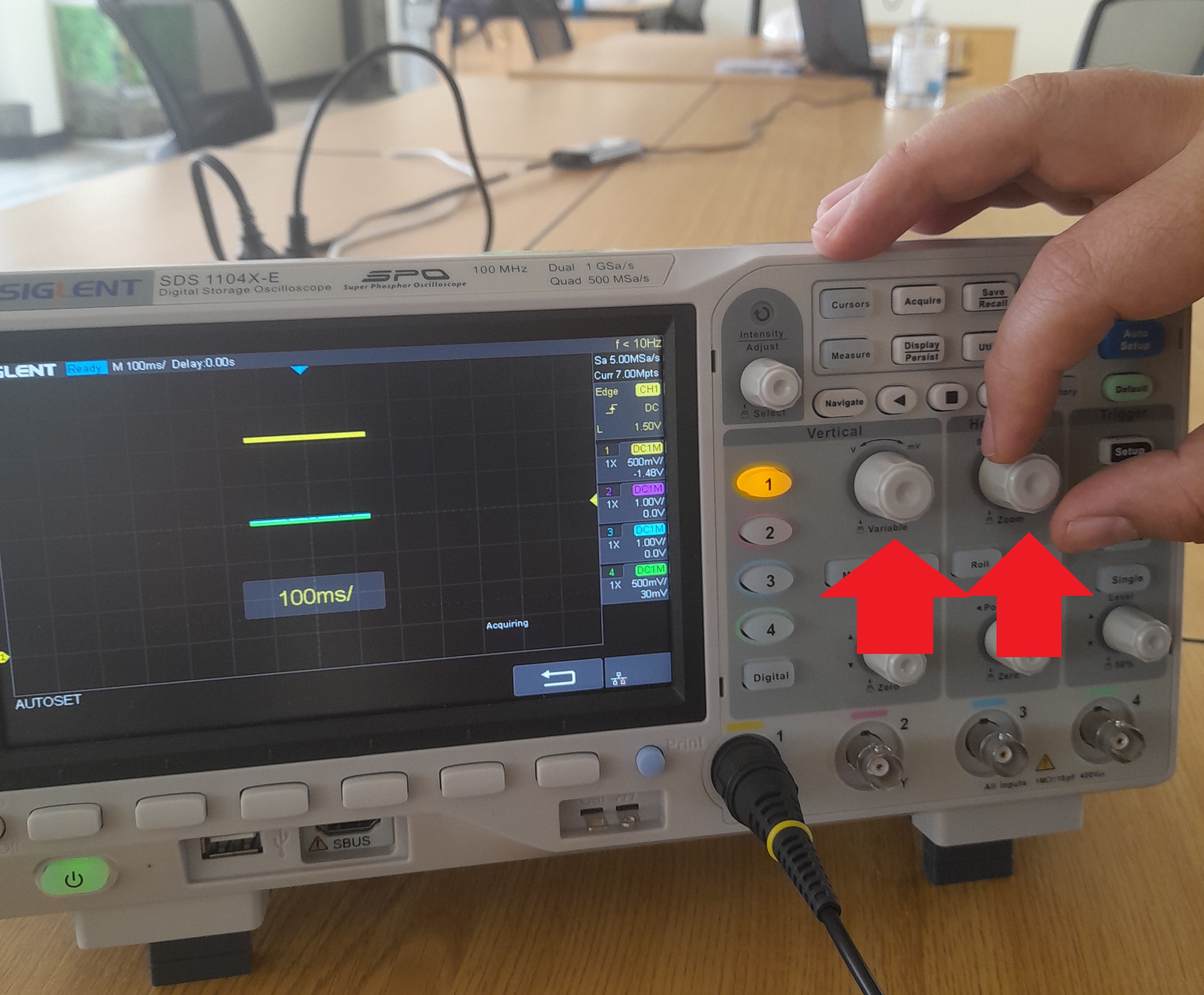
For the control of these two variables (voltage and time) there are two handles that can change the value of the grid that is presented in the graph, there are limits in the data acquisition based on time.
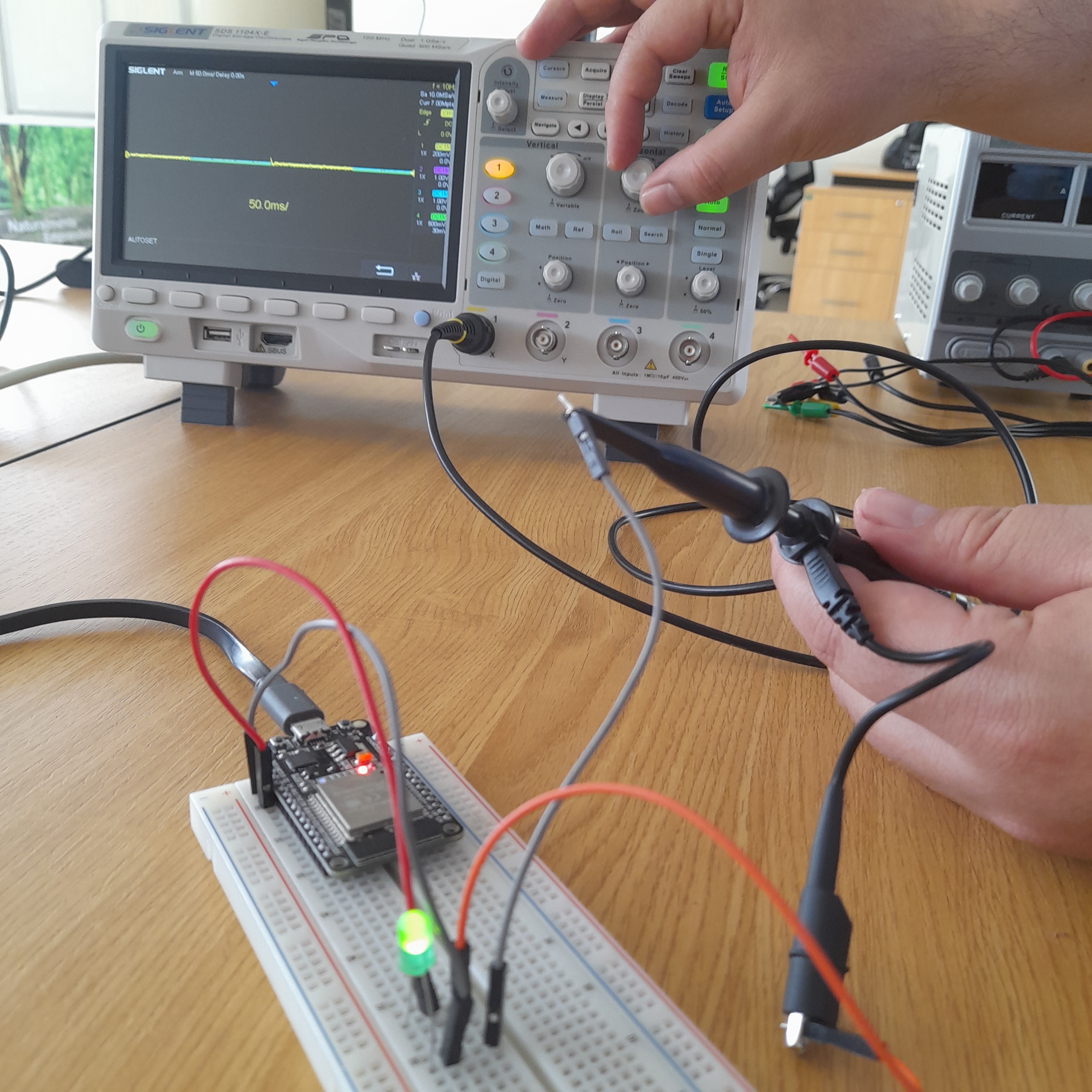
In the oscilloscope we have important buttons for the use process such as the "Auto Setup" that allows to automatically calibrate the signal processing. It is also important to consider that the oscilloscope model works by channels. In this case we are working with channel 1.
To make measurements with the oscilloscope, it is necessary to connect the crocodile to the negative terminal of the channel and the hook to the positive terminal.
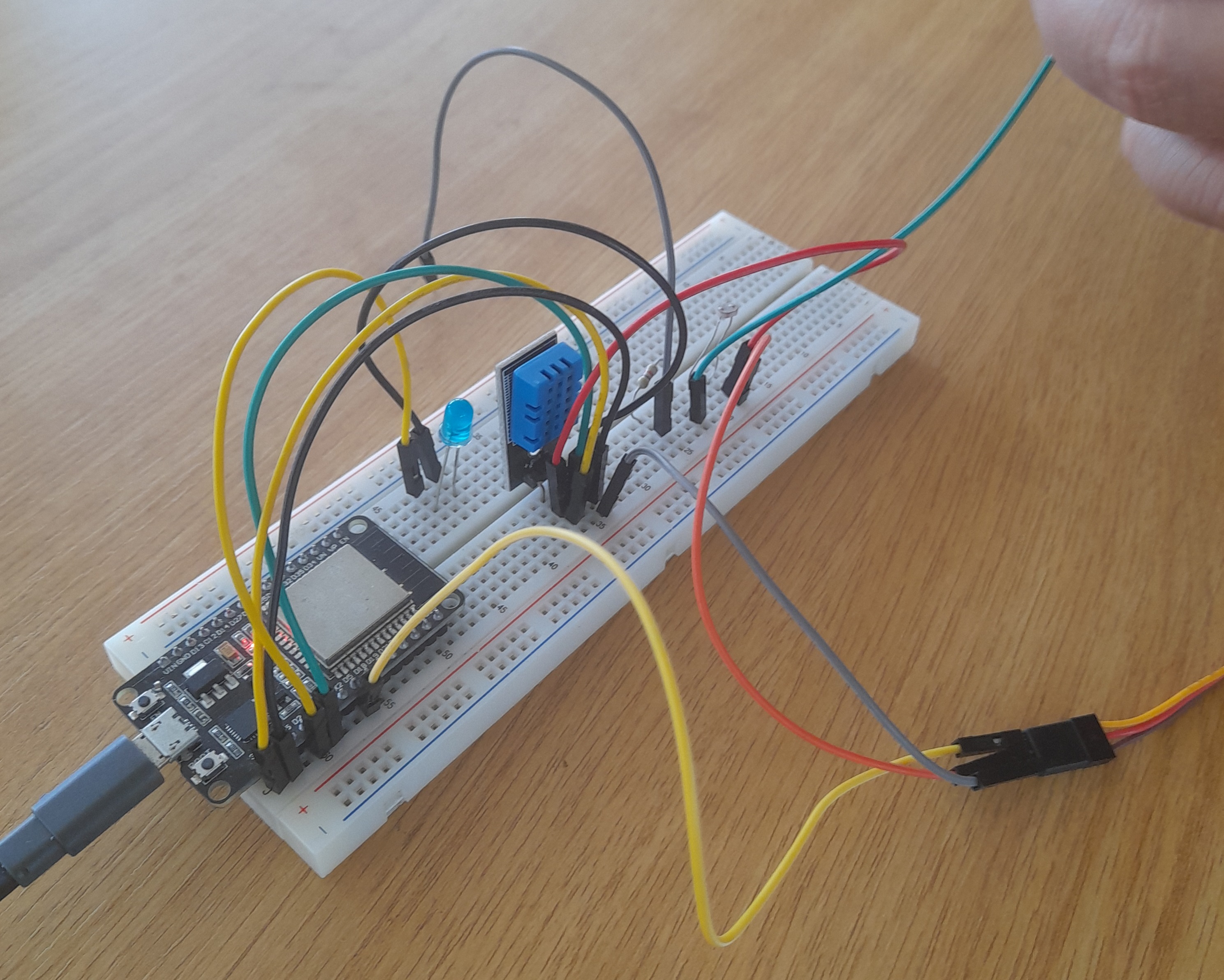
The type of board used for the tests is a connected Esp32 that receives power from its usb port which in turn is connected to the computer. The Esp32 pinout helped us connect the 3.3 V and GND outputs to a circuit built for a photoresistor and a DHT11 sensor.
The voltage reading on the card is displayed in mV (volts) and in the case of time in MS (milliseconds). The time and voltage intervals can be graduated with the vertical (Voltage), horizontal (time) control buttons.
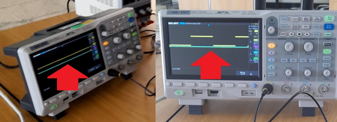
We observe that the analog reading shows a non-square undulating type graph while the analog signal does show a square-shaped signal since there is only the on and off order, there are no variations.
-
Digital Multimeter
A digital multimeter is a testing instrument used to measure two or more electrical values, primarily voltage (volts), current (amps), and resistance (ohms). It is a standard diagnostic tool for technicians in the electrical and electronic industries.
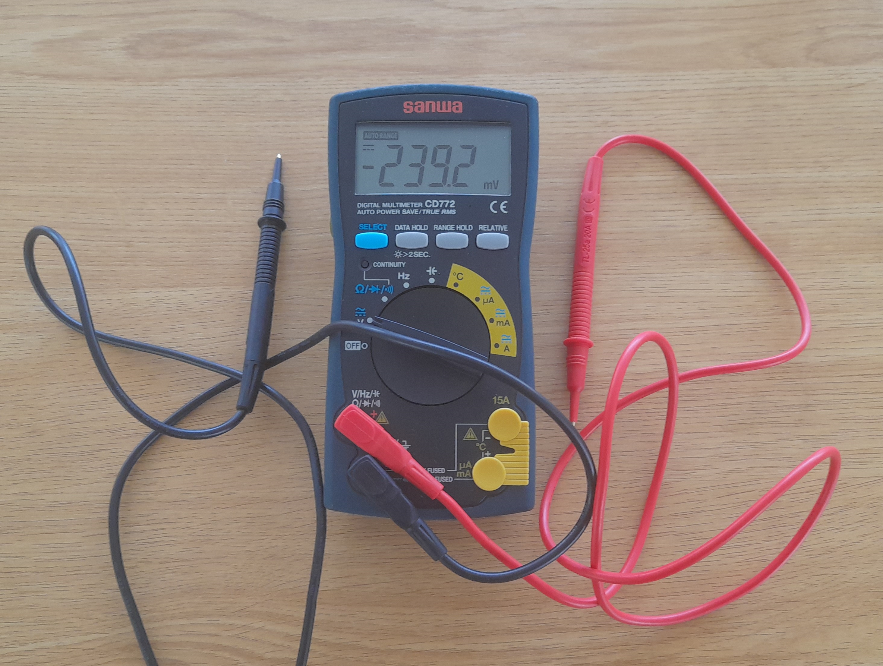
The multimeter model we use is the Sanwa CD772. This Digital Multimeter is useful for measuring/analyzing circuits of small communication devices, home appliances and batteries in the CAT ranges. II 1000 V and CAT. III 600V.
The test leads are flexible insulated leads (red for positive, black for negative) that plug into it. They act as the conductor from the material under test to the multimeter. The test leads on each cable are used to test the circuits.
-
Multimeter test.
To understand how the multimeter works it was necessary to review the multimeter user manual.
The multimeter can register the amount of voltage in an electrical circuit both in direct current and in alternating current, it is also possible to check the continuity of the electrical current.
To access the direct current voltage reading, the handle is placed in the direct current reading direction and the reading sign is observed. If in case the reading shows a negative value, it is necessary to invert the polarity of the reading.
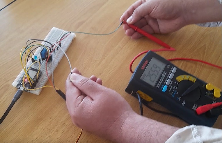
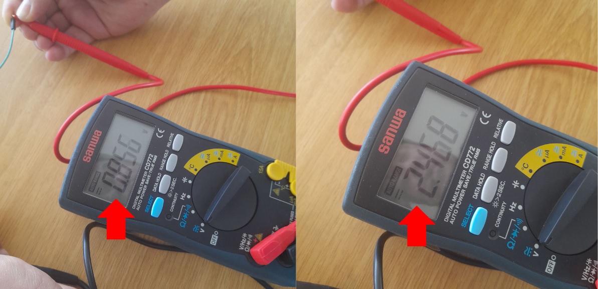
For this test, the multimeter was connected to an Esp32 board. Different voltage readings were observed.
In this test we observe that in the voltmeter we cannot have a record of the time. However, we can see the voltage change in the digital signal from 0 to 2.4 V when a “LOW” or “HIGH” command is issued from the microcontroller. We also observe multiple voltage changes on the analog sensor.
Individual assignment:
-
Redraw one of the echo hello-world boards or something equivalent, add (at least) a button and LED (with current-limiting resistor) or equivalent input and output, check the design rules, make it, test it. Optionally, simulate its operation.
For this assignment I made the following actions:
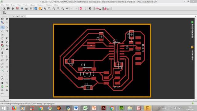
Step 1: The first thing I did was download the echo hello-world board and the Eagle program from Autodesk. EAGLE is a software for the design of printed circuit boards (PCBs).
Eagle has played a very important role in the circle maker / hacker for being one of the first options with limited free licenses. Eagle is a good software with multiple facilities for the design of PCBs, it is cross-platform and has a good community of users behind that release a large number of projects to use or study them.
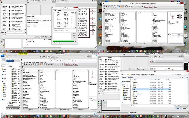
Step 2: Then I downloaded the "Fab" library from the Fab Academy website and saved it in the Eagle program library folder that was installed on my computer.
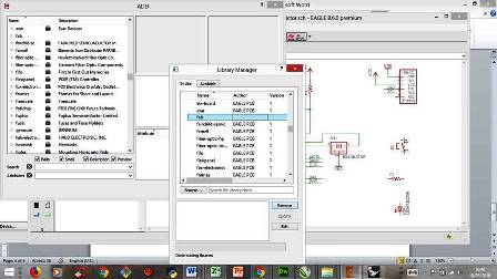
Step 3: Next I opened the Eagle program and tried to import the new "Fab" library using the library manager. I had some problems because the new library was not shown in the Eagle program. I had to re-download the library and reinstall the Eagle program, finally the library could be successfully imported into the tbspace file.
Step 4: Then I review the charge of the new library in Eagle and rename the name of the author of the library.
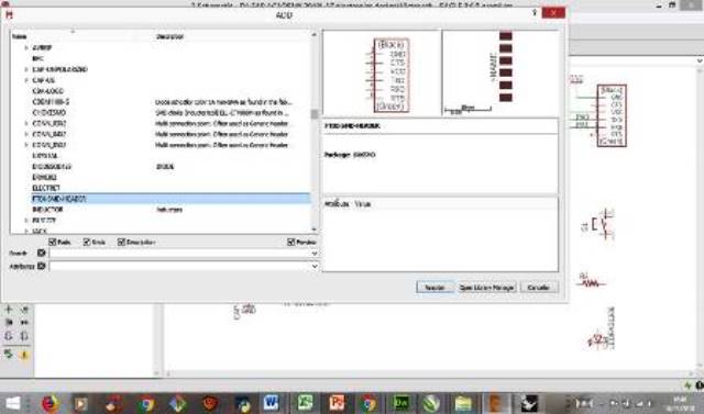
Step 5: Then I proceeded to insert the FTDI terminal in the schematic of the echo hello-world board.
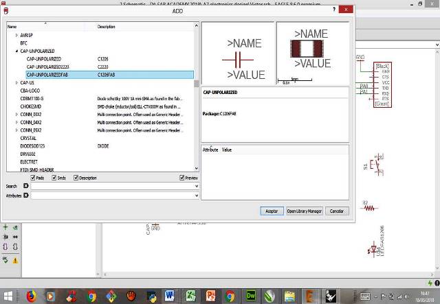
Step 6: Then I proceeded to insert the capacitor in the schematic of the echo hello-world board.
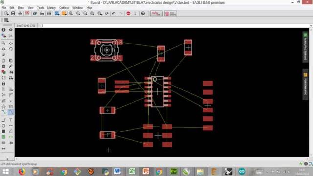
Step 7:Then I proceeded to connect the inserted devices of the "Fab" library in the schematic of the Eagle program.
Step 8: Then I proceeded to change the measurements of the connectors to 16 ml.
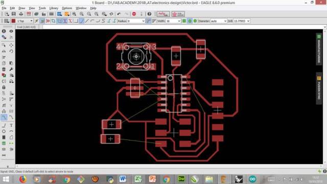
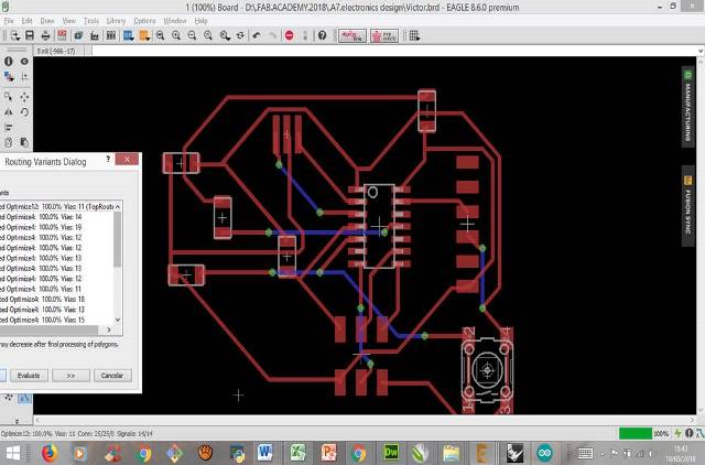
Step 9: Then I proceeded to make the path edition.
Step 10: Then I proceeded to correct the errors. I noticed that several connections were on top of each other. I had to erase and redo almost all the connections.
Step 11: It was very complicated to correct the errors of the connections. I had to try to find new routes for connections.
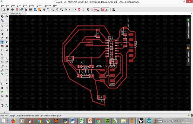
Step 12: Next I made sure that the connector paths do not overlap each other.
Step 13:I put the edge to the design and checked the order and the correct functioning of the connectors and the components.
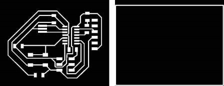
Step 14: Then I exported the files for the inside and the outside of the board.
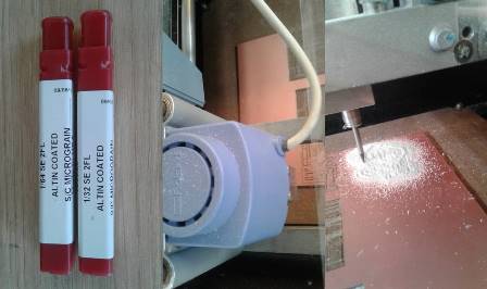
Step 15:The Roland Modela 3D Plotter MDX-20 milling machine was prepared. Then cut a piece of PCB bakelite plate. Then I put a glue paper so that the cut of the plate does not move from the work table. The 1/64 cutter was used for the inner cut and the 1/32 cutter was used for the outer cut.
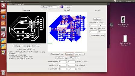
Step 16: Next, Then the Modela program was configured for the inner cut.
Step 17:Then the Modela program was configured for the outer cut.
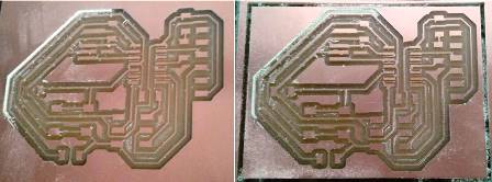
Step 18: At the end of the cuts I proceeded to clean the remains with an air vacuum.
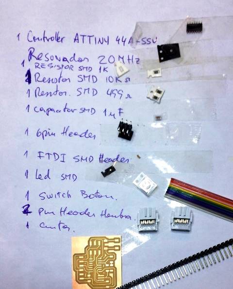
Step 19:The next step was to request the components of the PCB in the Fab Lab ESAN warehouse.
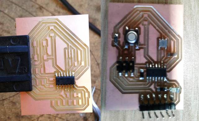
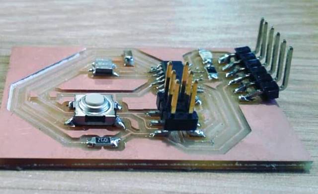
Step 20:The next step was to solder each component of the PCB one by one.
Step 21:Finally I checked that the components are correctly welded according to the schematic developed in the Eagle program.
