Final Project
Learning Outcomes:
-
Create your own integrated design.
-
Demonstrate 2D & 3D modelling capabilities applied to your own designs.
-
Select and apply appropriate additive and subtractive techniques.
-
Demonstrate competence in design, fabrication and programming of your own fabbed microcontroller PCB, including an input & output device.
What does it do?
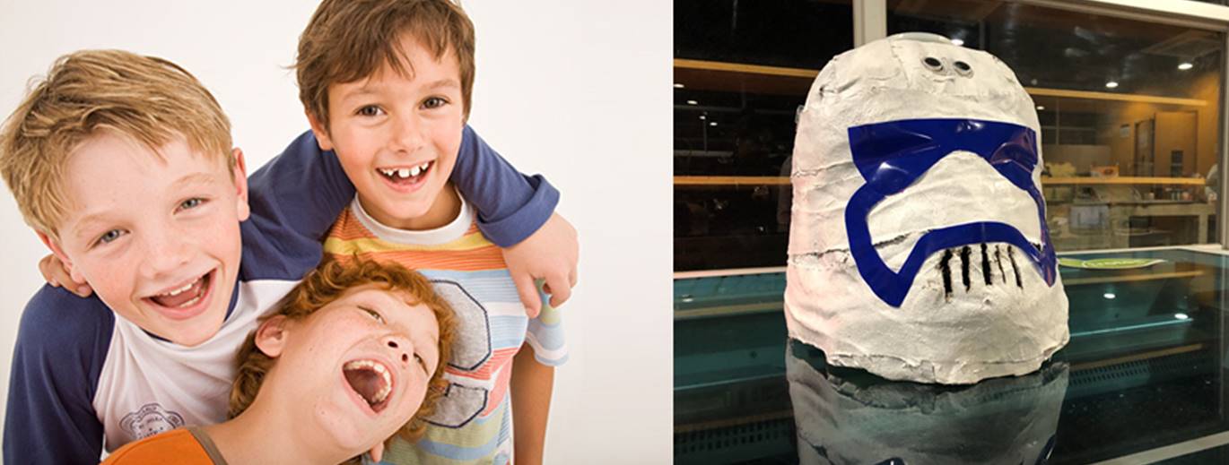
The project is an intelligent helmet that helps children develop spatial location skills. Spatial location ability typically develops in children 3 to 5 years of age. This ability is very important for the cognitive development of children because it allows us to locate ourselves in a spatial context. This cognitive ability allows the ability to perceive the environment from sizes, shapes, distances, etc. For this, it is essential to understand the location of the objects, the concepts of distance, speed and placement (left, right, front, back, top, bottom, top, bottom, etc.).
Planning of project tasks
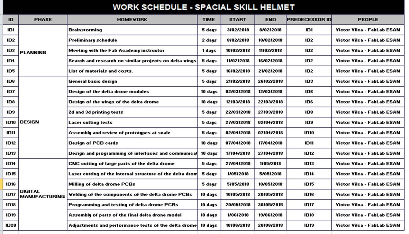
Who's done what beforehand?.
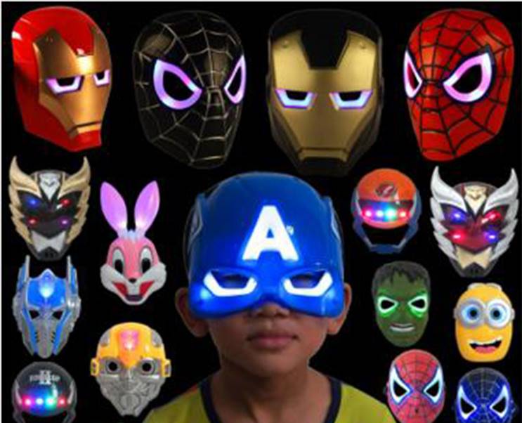
I have seen projects of smart helmets of Marvel or Star Wars characters built by fanatical makers of science fiction movies. I have also seen some computer programs that help children develop fine motor skills, including spatial location skills.
What did you design? What materials and components were used?
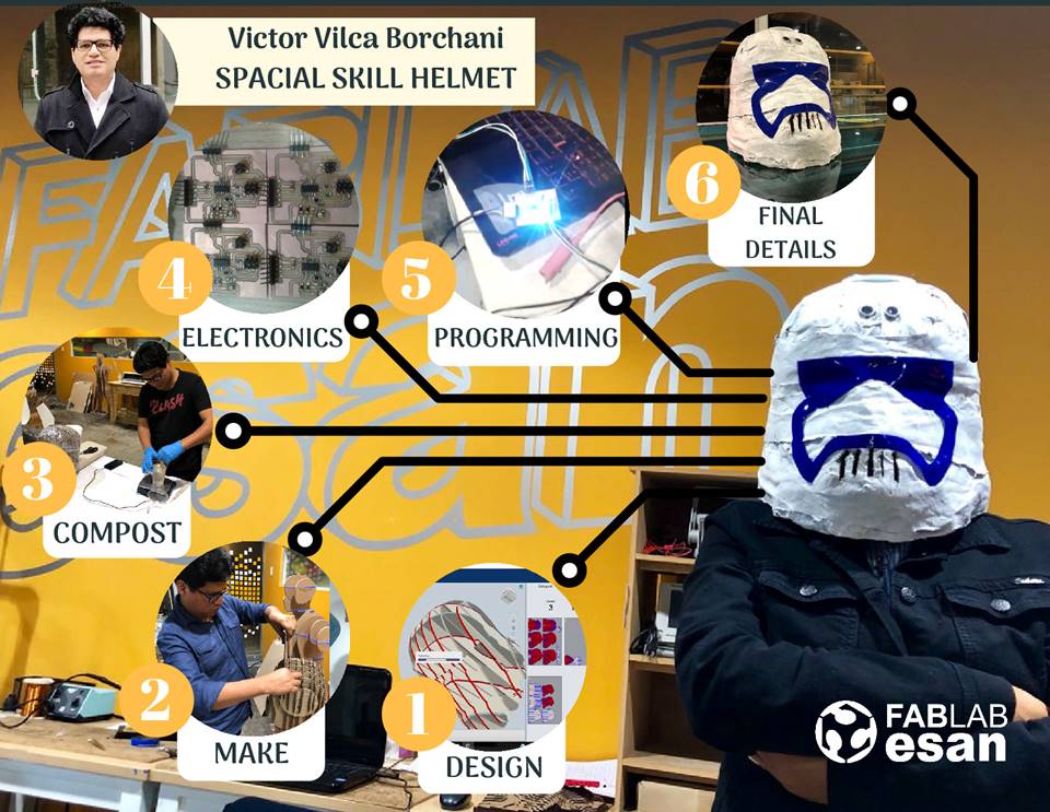
For the manufacture of the smart helmet I did the following steps:
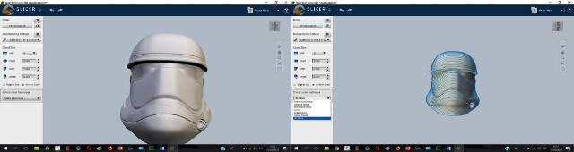
Step1: I designed a smart helmet.. For the design of the helmet I used the Slicer 3D program. Slicer for Autodesk® Fusion 360 ™ is a tool to turn your digital 3D models into appealing artefacts. It slices and converts 3D models into 2D patterns that you can cut out of any flat material. Download here.
This part of the final project was done in assignment 17: Wildcard Week.
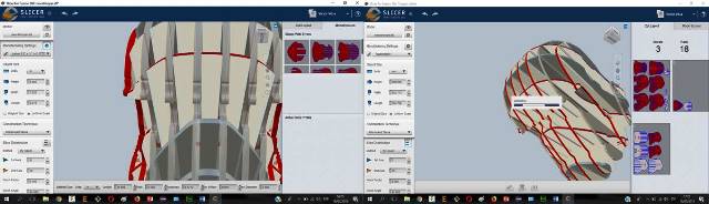
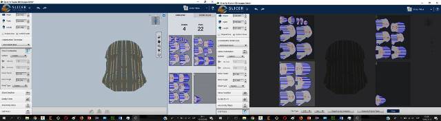
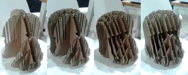
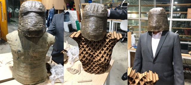
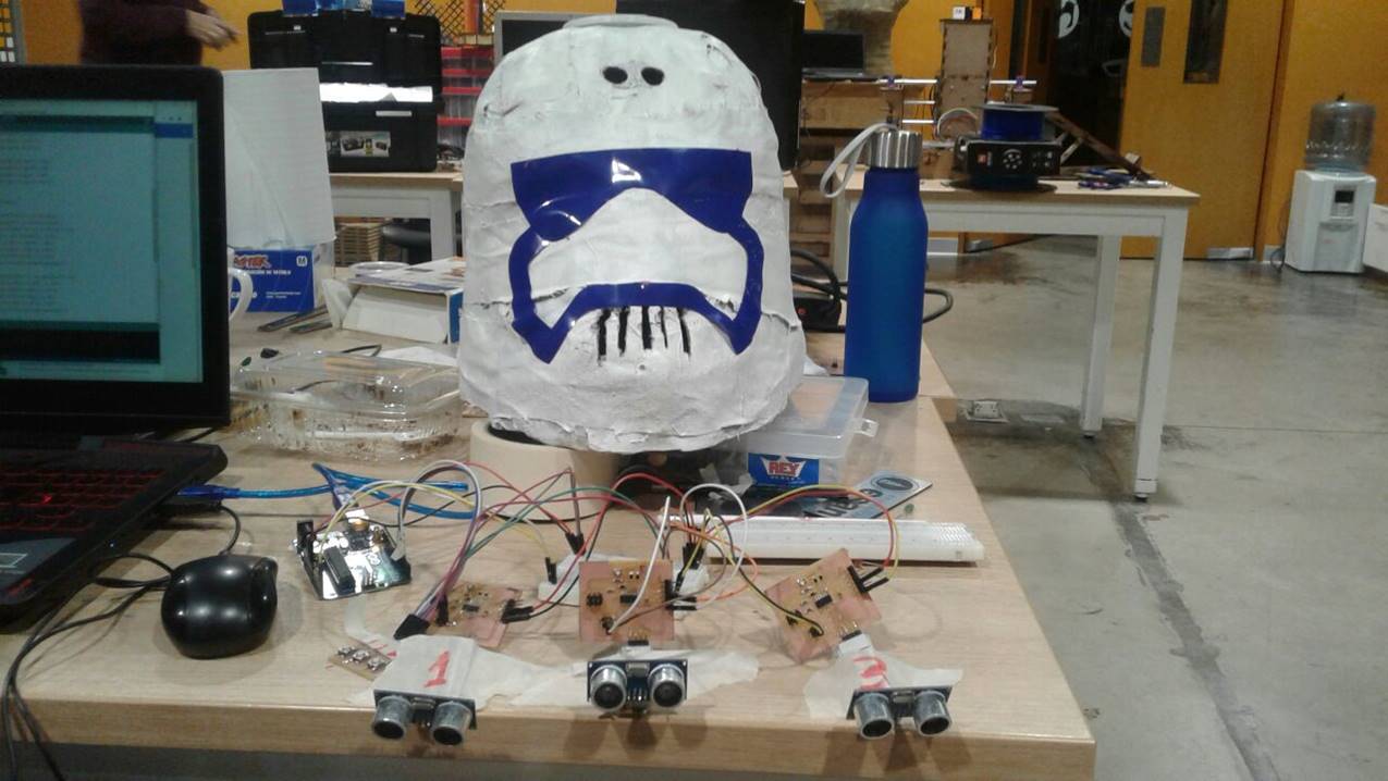
Step 2: For the reinforcement of the internal structure of the helmet I used cardboard paper cut with the laser cutter and assembled with press fit. After several fitting tests, 22 two-dimensional objects were placed on four cardboard paper plates. Then the design was exported in the DFX format so that it can be cut in the laser cutter. Then I made the cut of the 22 two-dimensional pieces using the laser cutter.
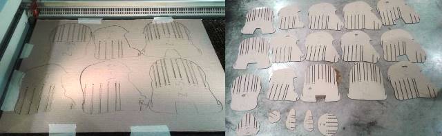
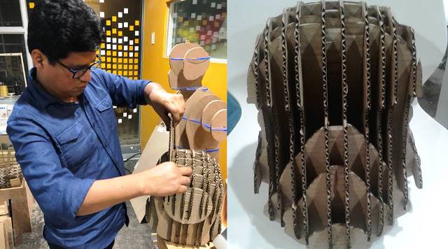
Step 3: Next I proceeded to assemble the printed pieces in the laser cutter. The assembly was simple because the pieces had a correlative numbering. When I was placing the last pieces I had some problems because the material was quite thin. After several attempts I was able to finish the helmet assembly.
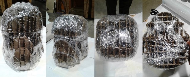
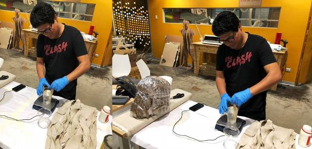
Step 4: I then covered the helmet with a layer of plastic cover. This I did in order to have a separating layer between the structure of the helmet made of cardboard and the layers of fabric with resin that I would use to cover the outside of the helmet. I requested the necessary materials to cover the helmet: resin and resin catalyst, cloth, protective lenses, plastic gloves, plastic cover, plastic cups and pallets.
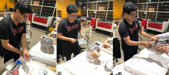
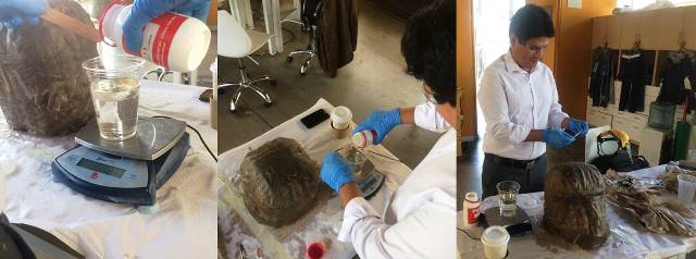
Step 5: For the armed the external structure of the helmet I used the compost technique. The materials used were plastic wrap, cloth, resin and resin catalyst. Next I used the electronic scale to mix 300 milliliters of resin with 60 milliliters of resin catalyst. The ratio to mix both components was 5 to 1. I used a palette of ice cream and gloves to make the mixture. Then cover a piece of cloth with resin and place it around the helmet. Repeated the process several times until completely covering the outer edge of the helmet. Finally I let the helmet dry for 24 hours.
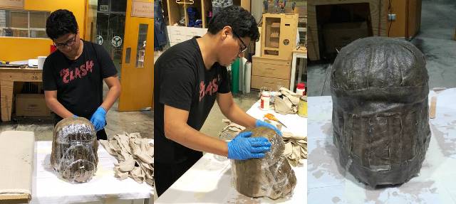
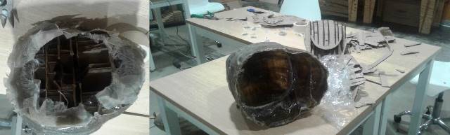
Step 6: The next day I went back to mixing the resin with the resin catalyst. Then I returned to cover the helmet with pieces of cloth with resin to form a second layer around the entire helmet. I let the piece dry for another 24 hours. The next day I checked that the coverage of the helmet was already totally hard. I proceeded to remove the material inside the helmet until I had only the outside part. Finally I checked the size of the helmet by placing it next to other similar structures.
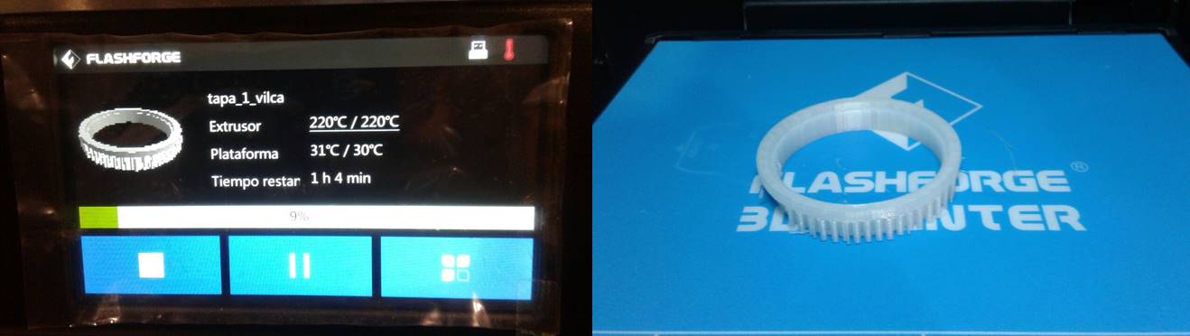
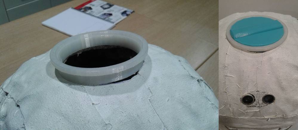
Step 7: For the upper part of the helmet it was necessary to design a kind of circular cover. The cover would serve to place supports for the electronic cards that should be located inside the helmet. The printing of the two parts of the cover lasted approximately 4 hours. The printing was made on a BCN3D Sigma printer. The material used for the printing was PLA.
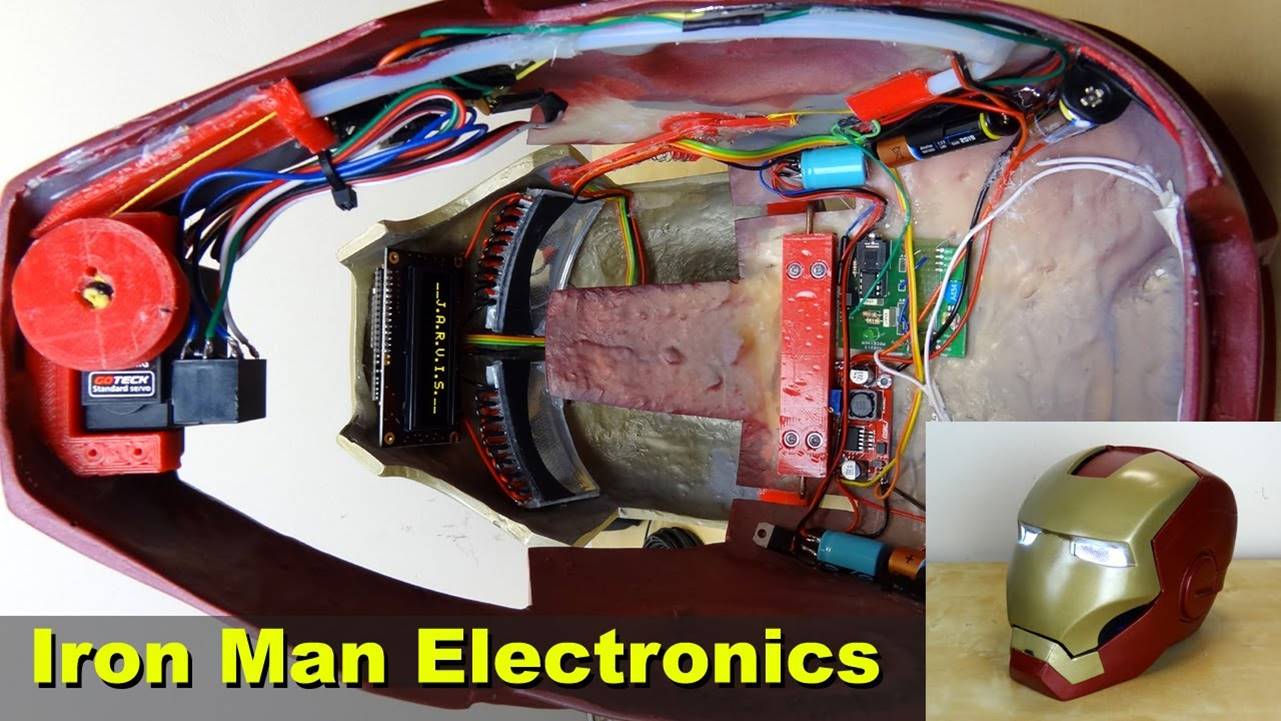
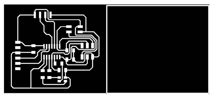
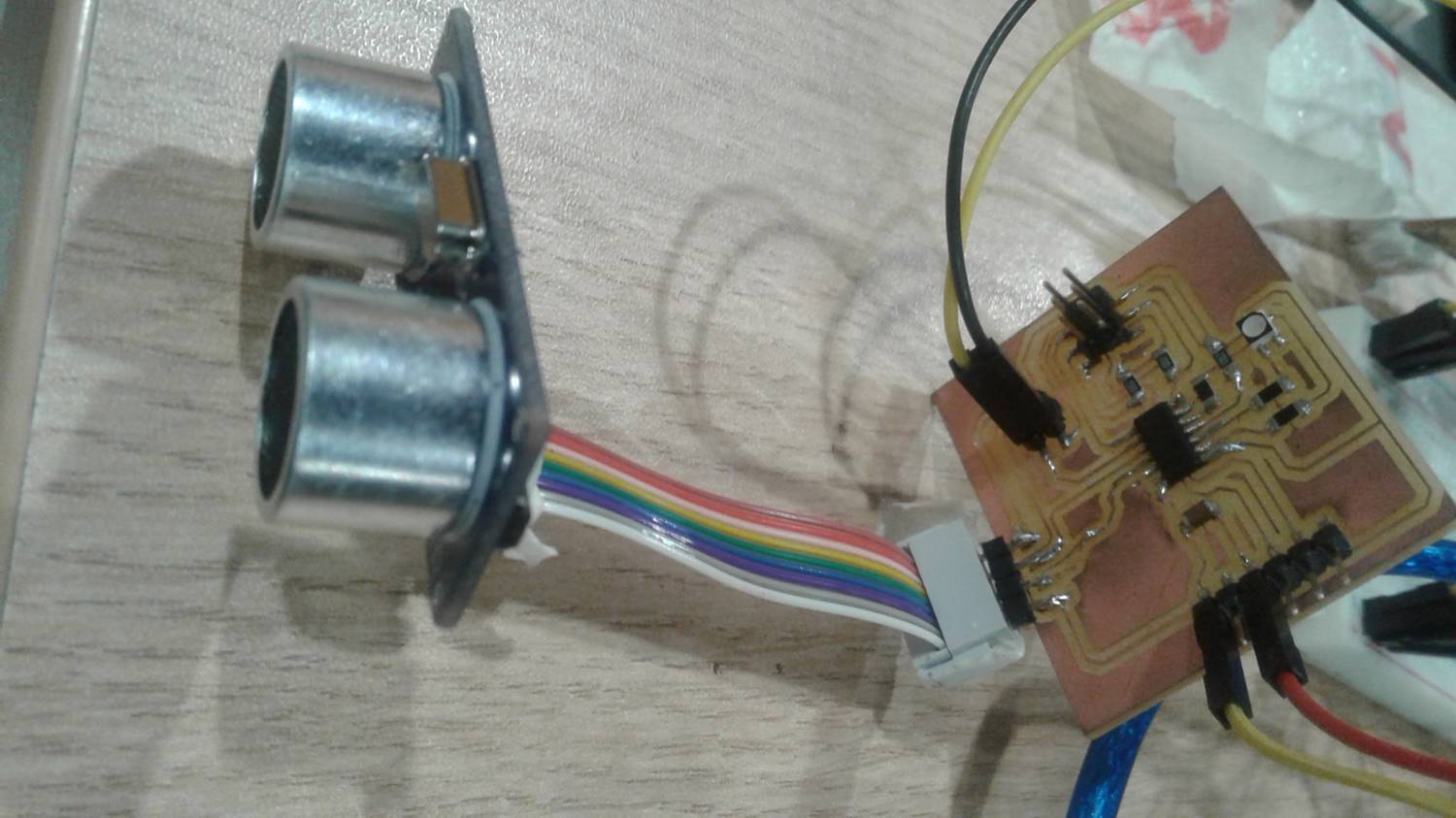
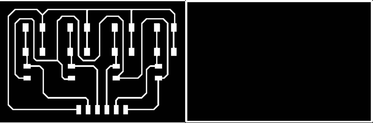
Step 8: Next, it was necessary to design a PCB with the necessary components that receive the signal from an ultrasound sensor and that can turn on an LED depending on the distance of the object received by the sensor. The Eagle program was used to design the card.
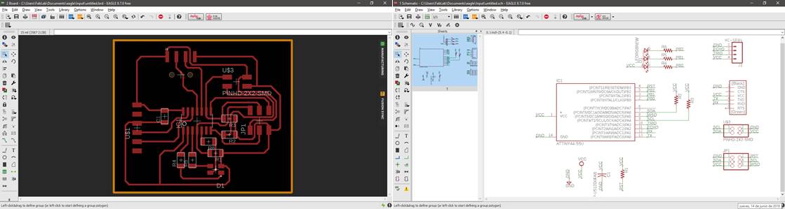
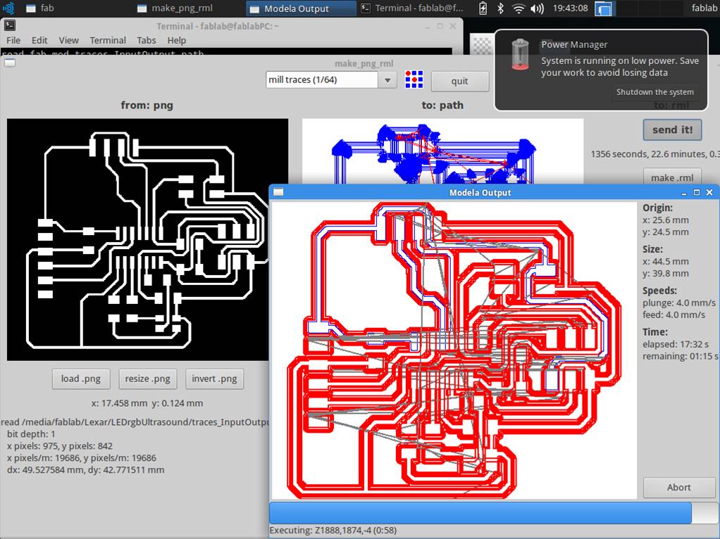
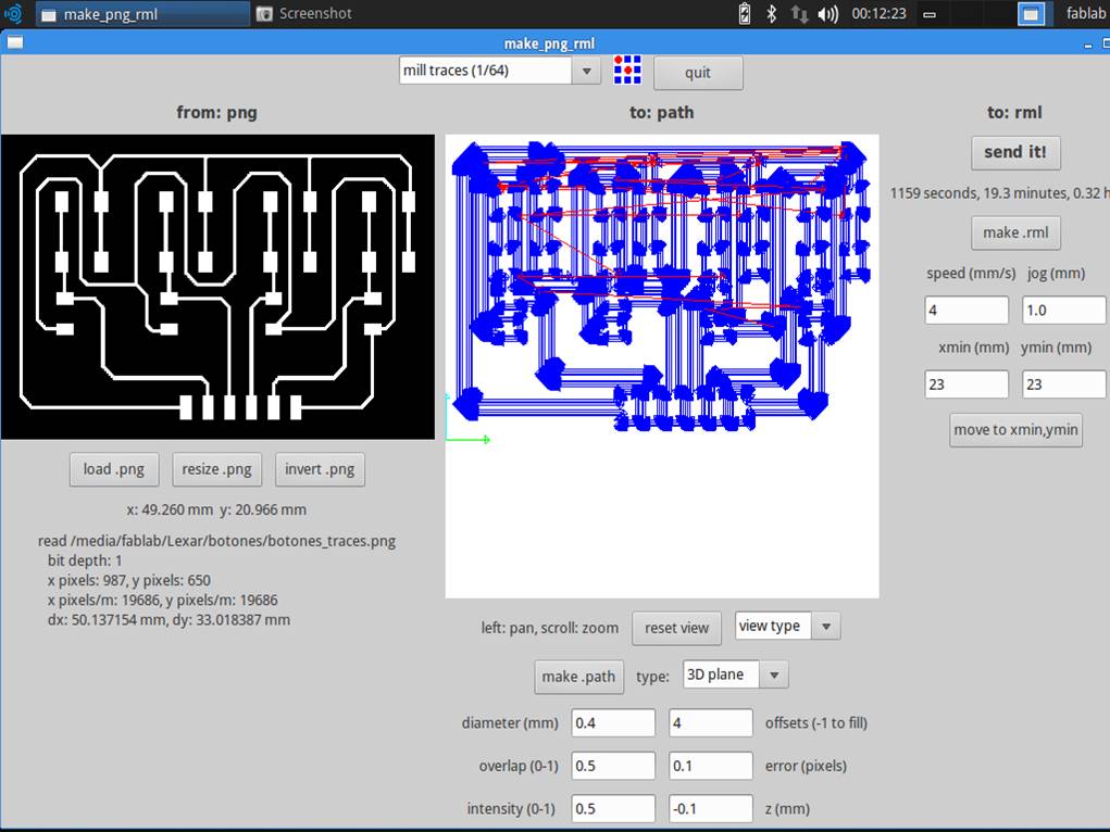
Step 9: Next, the tracer and interior images are exported in .png format to be milled.
Step 10: The cards were then milled using a Roland Modela MDX 20 milling machine. For the milling of the PCB, 1/64 and 1/32 cutters were used.
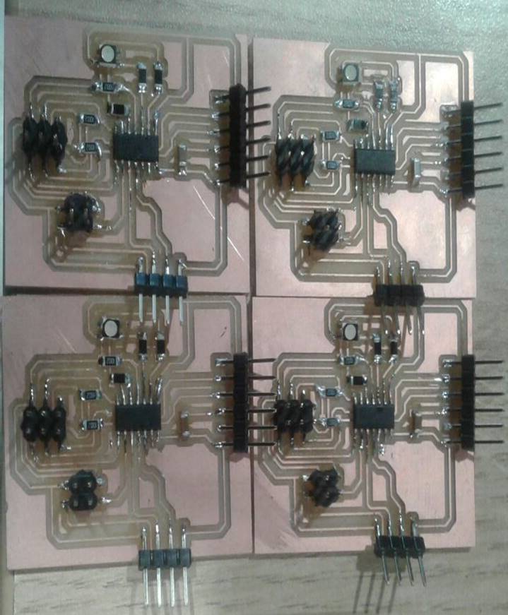
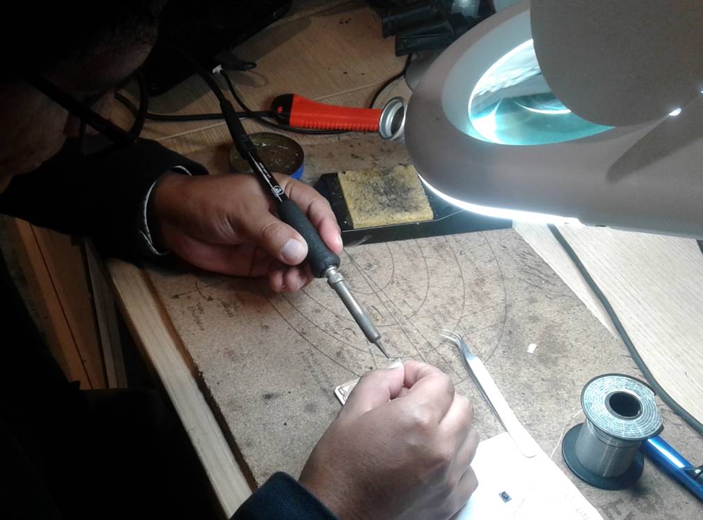
Step 11: The components of the PCB were then welded according to the schematic previously designed in the Eagle program.
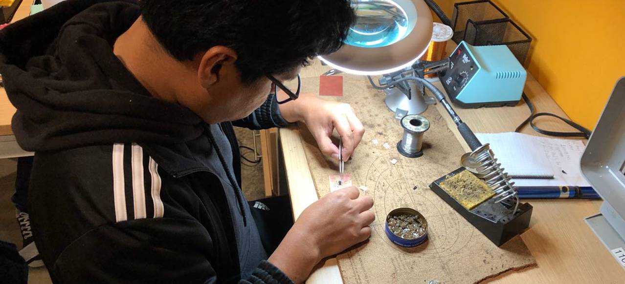
Step 12: The process of milling and welding components of the PCB was repeated four times. It was necessary to have 4 PCBs to be able to locate the 4 cardinal points within the smart helmet: north, south, east and west.
Step 13: Then the card was connected to an ultrasound sensor.
Step 14: Next, the necessary code was written to make the PCB detect objects near the ultrasound sensor and turn on a led if an object is located 20 centimeters away from the sensor. The programming was done using the Arduino program.
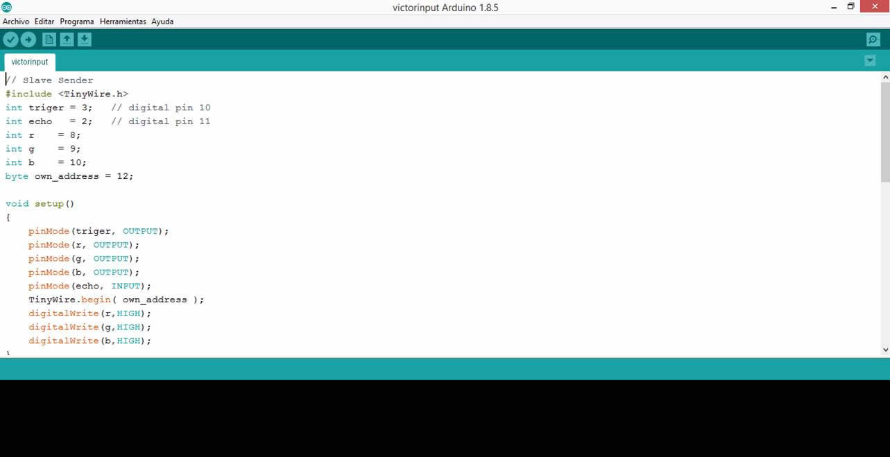
// Slave Sender
#include <TinyWire.h>
int triger = 3; // digital pin 10
int echo = 2; // digital pin 11
int r = 8;
int g = 9;
int b = 10;
byte own_address = 12;
void setup()
{
pinMode(triger, OUTPUT);
pinMode(r, OUTPUT);
pinMode(g, OUTPUT);
pinMode(b, OUTPUT);
pinMode(echo, INPUT);
TinyWire.begin( own_address );
digitalWrite(r,HIGH);
digitalWrite(g,HIGH);
digitalWrite(b,HIGH);
}
void loop()
{
float duration;
int distance=0;
digitalWrite(triger,LOW);
delayMicroseconds(2);
digitalWrite(triger,HIGH);
delayMicroseconds(10);
duration = pulseIn(echo,HIGH);
// distance =((time(us)*sound_speed(m/s))/2)*(100(cm)/1(m)*1(s)/1000000(us))
distance = round(duration*340/20000.0); // distance in cm
if (distance<20)
{
TinyWire.onRequest( onI2CRequest );
for(int i =0;i<5;i++)
{
digitalWrite(r,LOW);
digitalWrite(g,LOW);
digitalWrite(b,LOW);
delay(50);
digitalWrite(r,HIGH);
digitalWrite(g,HIGH);
digitalWrite(b,HIGH);
delay(50);
}
}
}
void onI2CRequest() {
TinyWire.send('F');
}
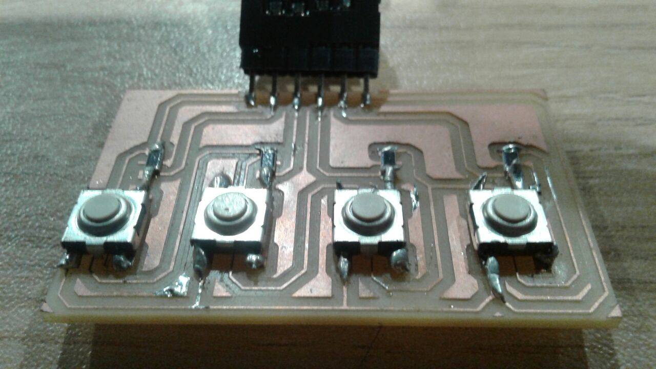
Step 15: Then it was necessary to design another PCB with 4 buttons and their respective components so that pressing a few buttons could indicate the exact location of the LED that is lit inside the smart helmet.

Step 16: Next, the tracer and interior images are exported in .png format to be milled.
Step 17: The cards were then milled using a Roland Modela MDX 20 milling machine. For the milling of the PCB, 1/64 and 1/32 cutters were used.
Step 18: The components of the PCB were then welded according to the schematic previously designed in the Eagle program.
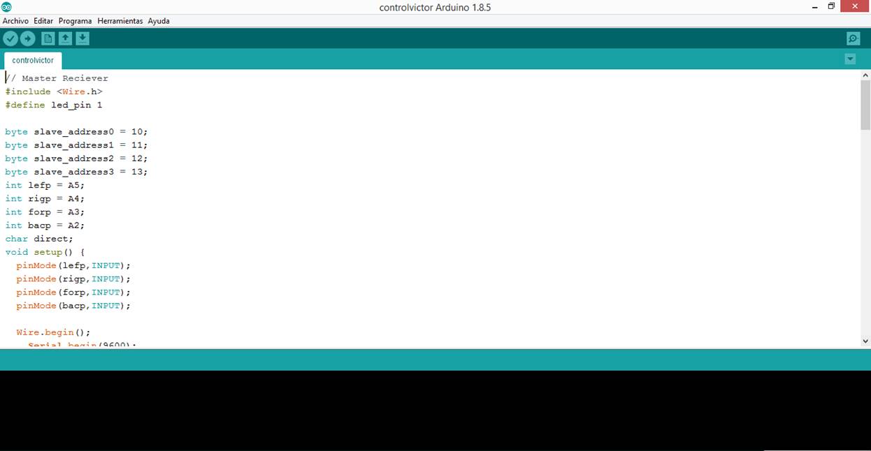
Step 19: Then the code was written so that the four buttons of the PCB allow the user to correctly detect which led was turned on. Also the PCB should indicate in an interface if the pressed button was the correct or the wrong one.
#include <Wire.h>
#define led_pin 1
byte slave_address0 = 10;
byte slave_address1 = 11;
byte slave_address2 = 12;
byte slave_address3 = 13;
int lefp = A5;
int rigp = A4;
int forp = A3;
int bacp = A2;
char direct;
void setup() {
pinMode(lefp,INPUT);
pinMode(rigp,INPUT);
pinMode(forp,INPUT);
pinMode(bacp,INPUT);
Wire.begin();
Serial.begin(9600);
int lefv=digitalRead(lefp);
int rigv=digitalRead(rigp);
int forv=digitalRead(forp);
int bacv=digitalRead(bacp);
Serial.println(lefv);
Serial.println(rigv);
Serial.println(forv);
Serial.println(bacv);
Serial.println("aaaaa");
}
void loop() {
/*if( Wire.requestFrom( slave_address0, 1 ) == 0 ) {
while(Wire.available()){
direct=Wire.read();
}
}
if( Wire.requestFrom( slave_address1, 1 ) == 0 ) {
while(Wire.available()){
direct=Wire.read();
}
}*/
Serial.println("aaaaa");
Wire.requestFrom( slave_address2, 1 );
Serial.println("aaaaa");
Wire.requestFrom( slave_address2, 1 );
Serial.println("aaaaa");
while(Wire.available()){
direct=Wire.read();
}
/*if( Wire.requestFrom( slave_address3, 1 ) == 0 ) {
while(Wire.available()){
direct=Wire.read();
}
}*/
int lefv=digitalRead(lefp);
int rigv=digitalRead(rigp);
int forv=digitalRead(forp);
int bacv=digitalRead(bacp);
Serial.println(lefv);
Serial.println(rigv);
Serial.println(forv);
Serial.println(bacv);
Serial.println("aaaaa");
delay(1000);
if(lefv==1||rigv==1||forv==1||bacv==1){
/*if (direct=='L'){
if(lefv==1)
{ Serial.println("Correct");
}
else
{Serial.println("Incorrect");
}
}
if (direct=='R'){
if(rigv==1)
{ Serial.println("Correct");
}
else
{Serial.println("Incorrect");
}
}*/
if (direct=='F'){
if(forv==1)
{ Serial.println("Correct");
}
else
{Serial.println("Incorrect");
}
}
/* if (direct=='B'){
if(bacv==1)
{ Serial.println("Correct");
}
else
{Serial.println("Incorrect");
}
}*/
}
}
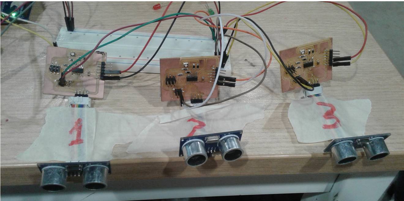
Step 20: I connect three cards to a microcontroller. Each card had the function of reading the distance with an ultrasound sensor. Each ultrasonic sensor was programmed to turn on a led when it detected objects located 20 centimeters away. I have used this library for the OIC communication between the Attiny 44 microcontrollers: TinyWire.
Where did they come from?
All the components, materials, tools and equipment prevented from Fab Lab ESAN. To take control of the materials used throughout the Fab Academy program, a warehouse management program developed in the FabLab ESAN itself was used.
How much did they cost?
According to the warehouse management software, the total development cost of the final project was $ 250. The cost includes materials, components, use of equipment, use of machines and external advice.
What parts and systems were made?
The inner and outer part of the helmet, the helmet caps, the helmet electronic cards and the buttons that activate the responses to the stimuli of the RGB lights were built.
What processes were used?
The processes of additive manufacturing (3D printing) and the processes of subtractive manufacturing (milling of electronic cards) were used. Also the electronics design and production, microcontroller interfacing and programming and the system integration and packaging were used.
What questions were answered?
The following questions were answered:
Is it possible to build a toy that helps children develop spatial location skills?
Is it possible to design the internal structure of a helmet with the image of a movie or television personality?
Is it possible to design, mill, weld and program electronic cards to detect objects located around the helmet?
Is it possible to design, mill, weld and program electronic cards that allow storing information about hits and errors when detecting objects located around the helmet?
How was it evaluated?
The project was evaluated by two children between three and five years old who tested the helmet in two spatial location tests. Both children commented that the helmet seemed like a fun toy. Both children had a level of success greater than 90% when detecting objects located around the helmet.
What are the implications?
I believe that the smart helmet is a prototype that needs to be improved and put to various tests in terms of its structure, operation, electronics and usability. It is necessary to confirm if it can actually be a valuable tool to develop spatial location ability in children between 3 to 5 years of age.
If the tests are favorable, you could think of building other helmets with other structures and other functionalities that can help children develop other cognitive skills.
It is necessary to indicate that the project has a social purpose and that if it becomes successful the entire design, manufacturing, electronic and documentation process would be available to schools, families, children, adults, teachers, students, and any organization or person in general that you want to use it.