Electronics Design
01
Asigment
Group Project
Use the test equipment in your lab to observe the operation of a microcontroller circuit boardIndividual Project:
Redraw the echo hello-world board
- Add (at least) a button and LED (with current-limiting resistor) check the design rules, make it, and test it.
- Extra credit: simulate its operation.
- Extra credit: render it.
Resource
Software
Download File
Tutorial
Group Project
02

Individual Project
02
for the circuit design I use the program called eagle, previously I used another program but this time I ventured to learn how to use it since I did not know it. for the design we open as a new file a work area called schematic.
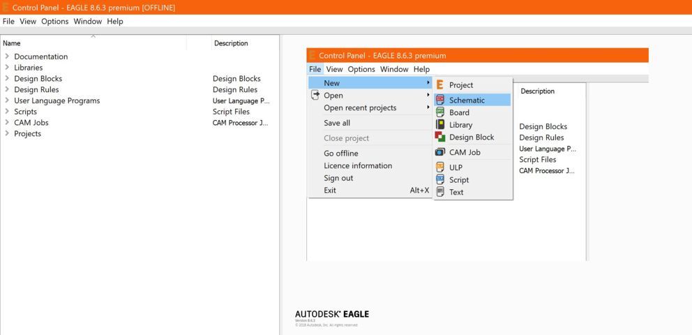
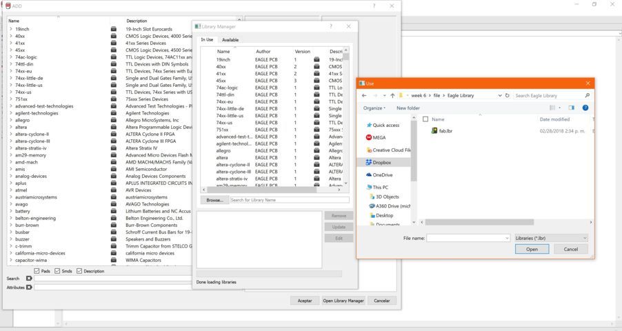
To have the components for the design we must add the fab library to eagle.
then we add the components that we ask in the fab tutorial, one by one.
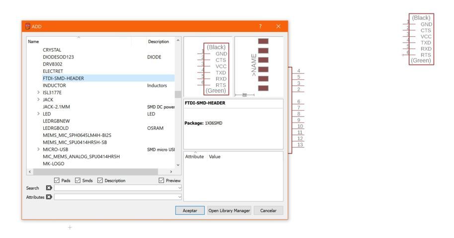
Along with the image that we provide the tutorial fab we must have all the necessary components.
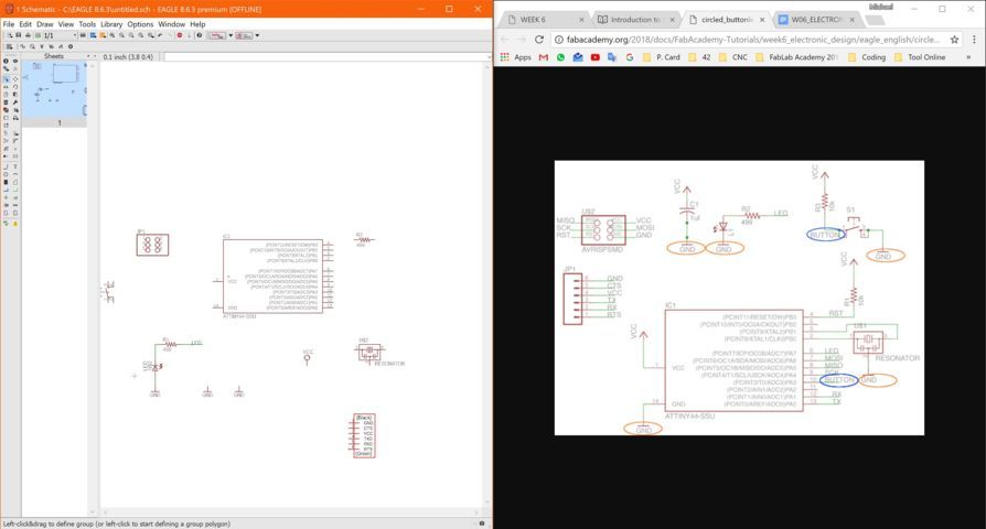
using the schematic design image we must connect all the components like this in the image. which uses a green line to make the connection name and label where, when defining the name, an automatic link is made.
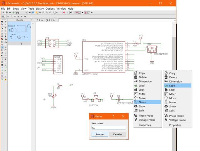
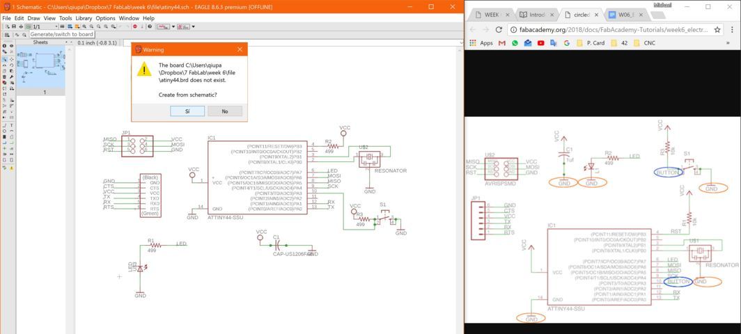
After having everything connected correctly, we must have the schematic design of the physical card.
Once you have the work area of ??the physical schematic of the card, you have to accommodate in the black area that you ask for, then you must reflect the track between the connected component. When I took this step, I realized that I was very small.
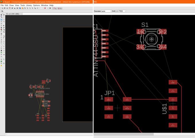
in the autorouter section, the track of the circuit is modified.

To have the proper settings of the autorouter, download a library on github that we provide in the tutorial fab.
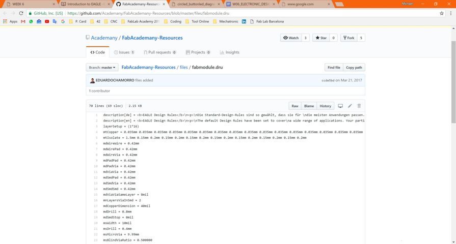
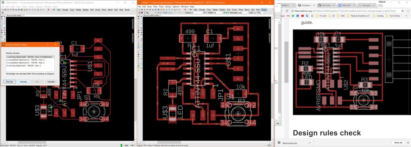
then click on autorouter and verify that they do not generate jumpers and that they are connected between components correctly
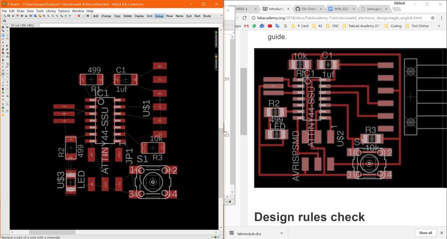
With the autorouter that we have just made, we must make the comparison of the image to be sure of its design.
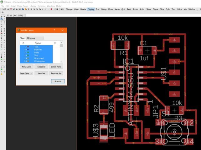
We select the view or the levels that do not want the circuit as etras and draw and export it in .png / monochromatic.
I used the fab modules again to generate the document or the languages ??for the cutting machine.
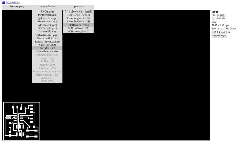
we must carry out the configuration with the cutting offset.
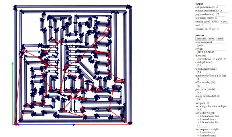
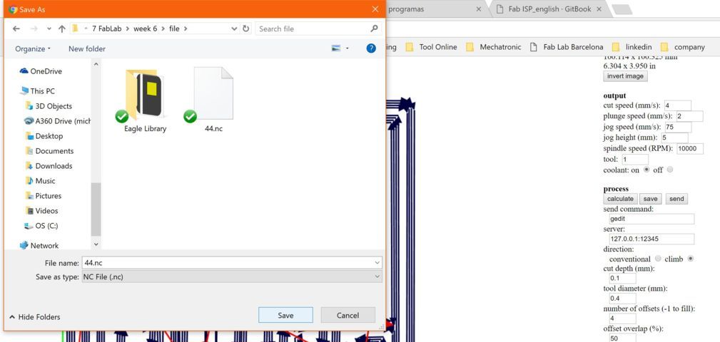
save the file that is in .nc as format.
using the GBRL Controller, let's look at the recently generated gcode file.

Before several cutting test you get to see the little imperfections but they were not serious.
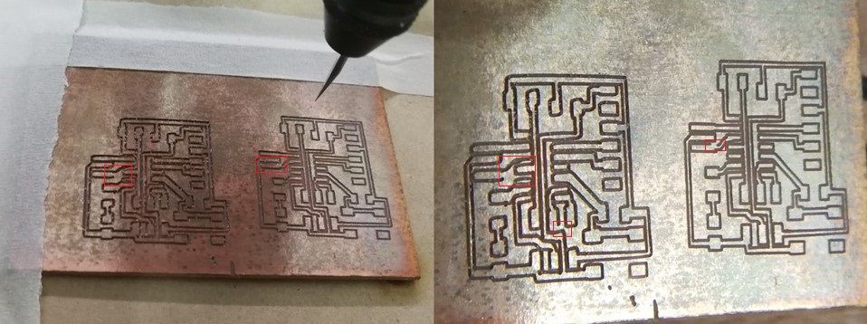
using the multimeter, we verify that the tracks are good and that they have a continuous connection.
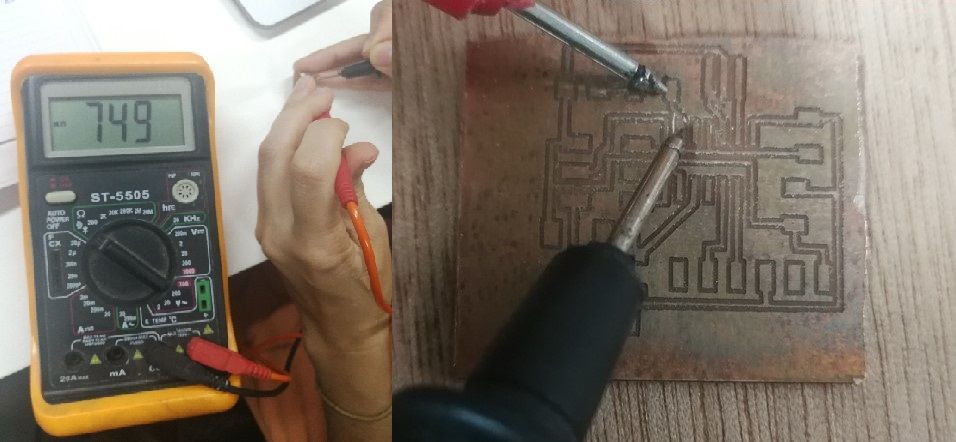
with a visturi cut the copper to separate from the unnecessary track.

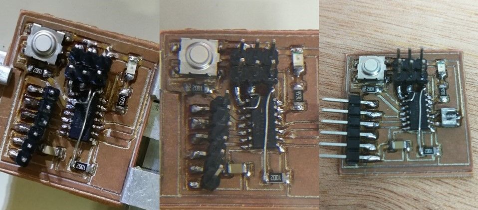
Then we solder all the electronic components to the card.
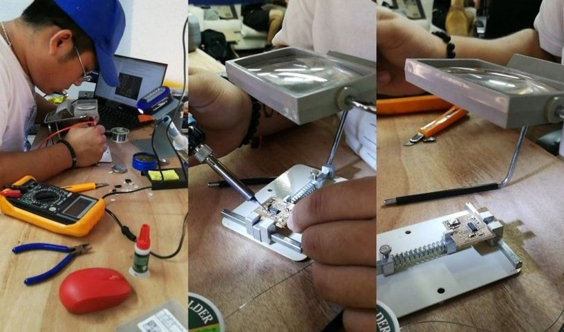
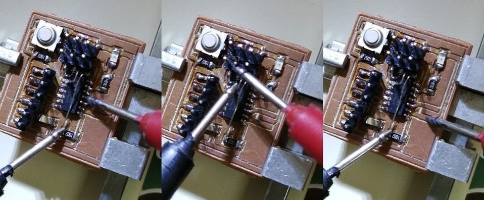
Verify that you have connectivity using the multimeter, if the multimeter sounds is because it has connection and if not it does not have connectivity.
for good luck I was separated from the other pins and the card.
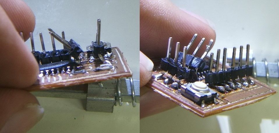
at the same time as the pins of which they were veered, that's why I removed them to solder the pins again, but this one is horizontal from the card.
