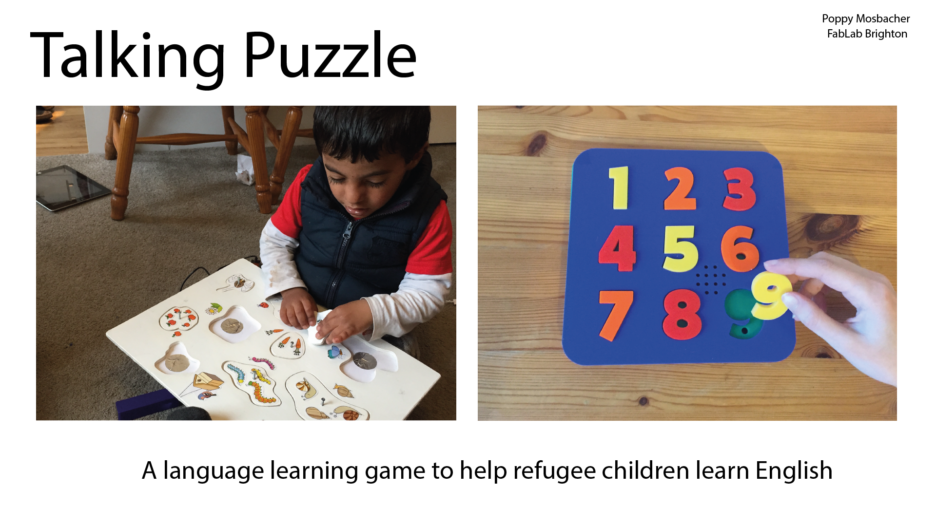
Final Result - Creating the Latest Prototype of the Talking Puzzle
Design Files
- Talking Puzzle Board and Numbers for Laser Cutting
- AAA Battery Holder for 3D Printing
- AAA Battery Holder STL file
- MP3 Board in Eagle
- MP3 Schematic in Eagle
- MP3 PNG File edited in Adobe Illustrator
- MP3 PNG Outline File created in Adobe Illustrator
Materials
- 6 x A4 Sheets of 3mm coloured acrylic or 1 Sheet 600mm x 400mm plywood and 3 different coloured paints
- Either a Leonardo Arduino or Components to make your own board:
- 90mm x 76mm (or larger) Copper Board for milling
- Surface mount components (in 1206 package size to fit circuit board pads):
- 5x 0.2uF Capacitor
- 2x 1uF Capacitor
- 2x 18pF Capacitor
- 10uF Capacitor
- 2 x 22ohm Resistor
- 499ohm Resistor
- 2x 0 ohm Resistor
- 680ohm Resistor
- ISP header
- Mini USB Female Socket
- Atmel AtMega32U4-AU
- Crystal
- DF Player Mini module
- 9 x LDR's (light dependent resistors)
- 10 x 1kohm Resistor
- Thin Speaker 0.25W 8 Ohm 40mm from Kitronik
- Small rocker switch
- Micro SD Card
- PLA to make a battery holder
- Battery contacts: Manufacturer Keystone 1 x 5202 from RS Components
- 2 x 5212
- 1 x 5225
- 2 x M3 x 10mm screws
- Single core wire
- Lead free solder
- Uhu glue
- Hot glue stick
- 500mm x 3.2mm Heat shrink wire sleeve
- 100mm x 10mm x 1mm acrylic to make circles to make it easier to glue LDR's (optional)
- Mini usb lead for programming the board
- PLA filament for storage box (optional)
Equipment
- Laser cutter
- CNC milling machine
- 3D printer
- Soldering iron
- Hot glue gun
- Black marker pen
Step 1 Laser Cut the Game Board
Please see more at Week 3.
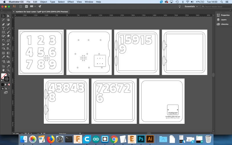
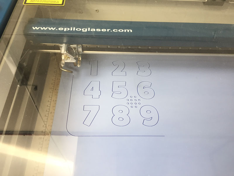
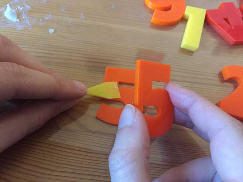
The Illustrator cutting file include two of each number so they can be glued together, as shown above. This means the puzzle pieces protrude from the board, as shown below, making them easier to lift out, without needing to source thicker acrylic.
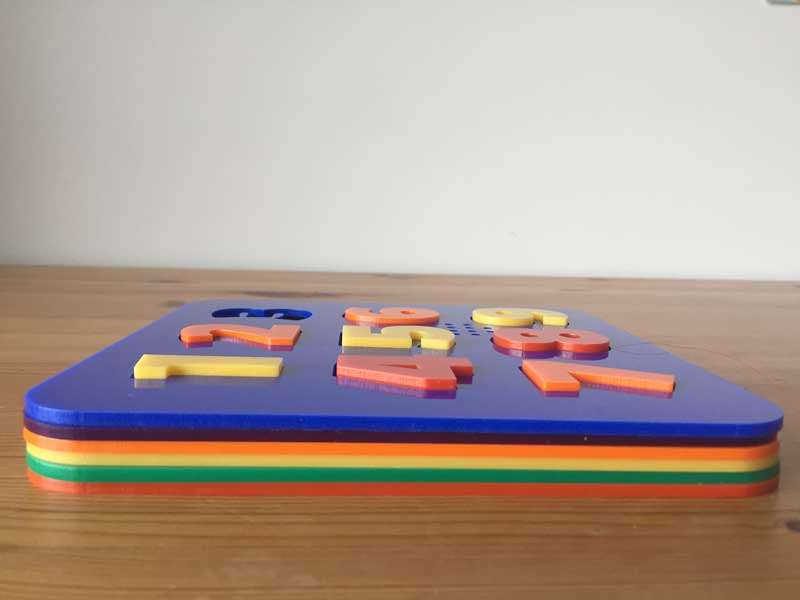
Order of Acrylic sheets:
- Blue - Top layer
- Green
- Yellow
- Orange
- Red
- Pink
- Purple - Bottom layer
Development shown on concept page
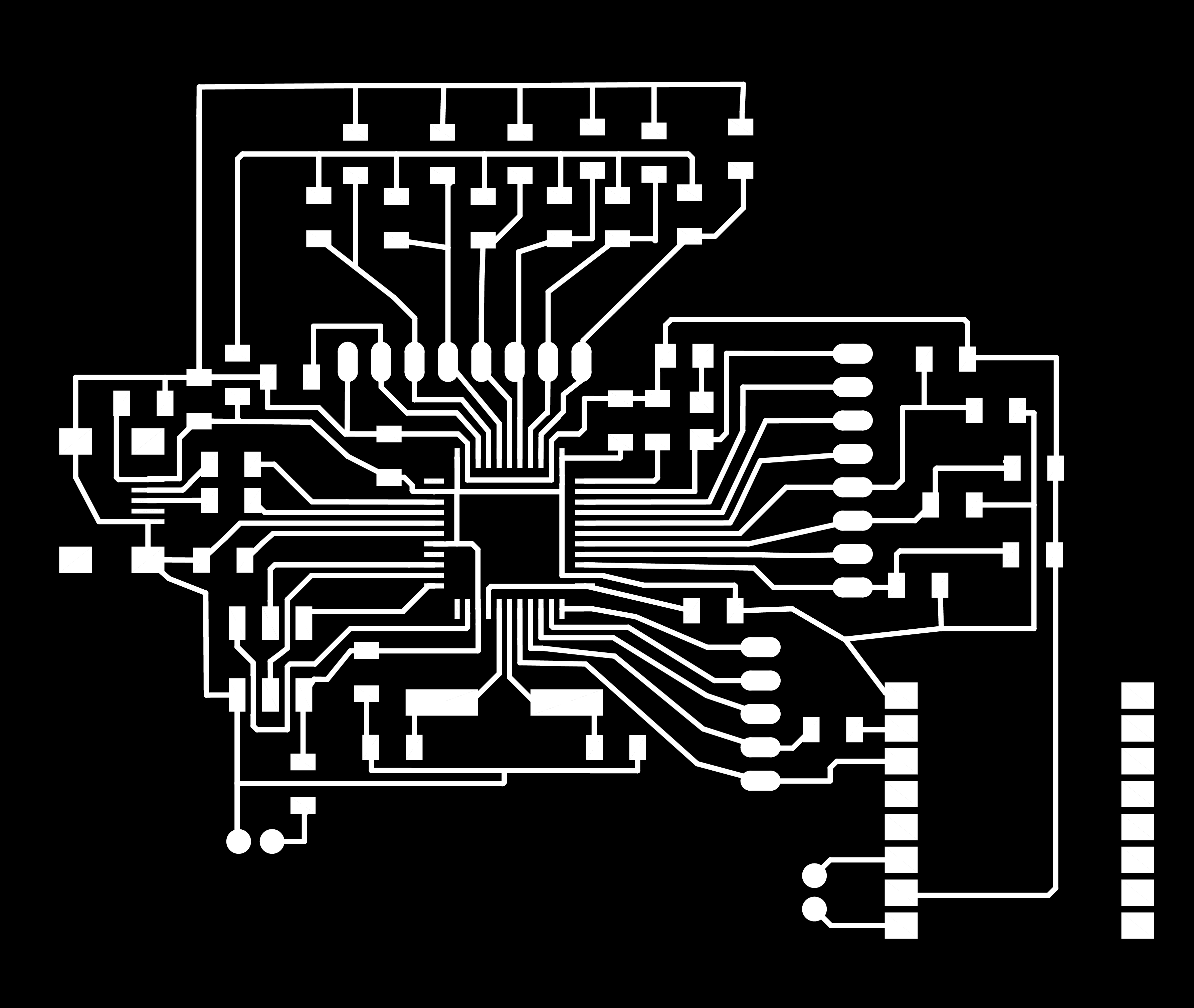
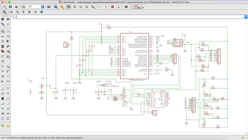
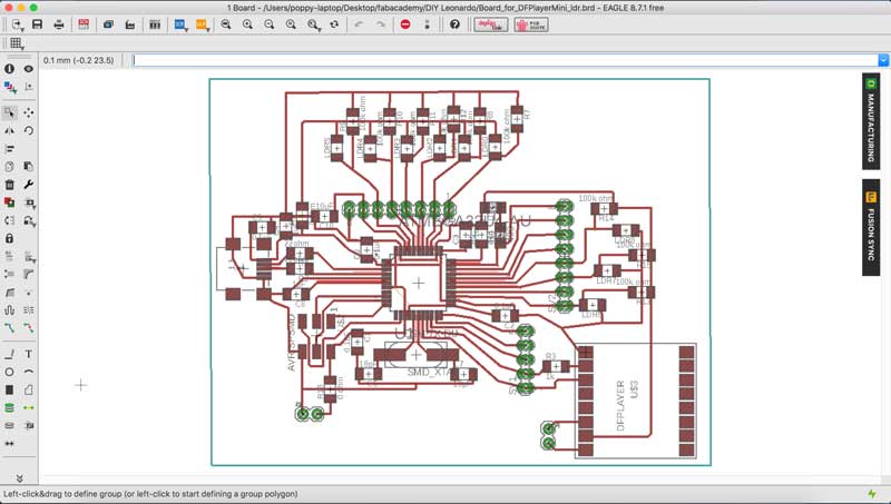
Step 2 Design the Circuit Board
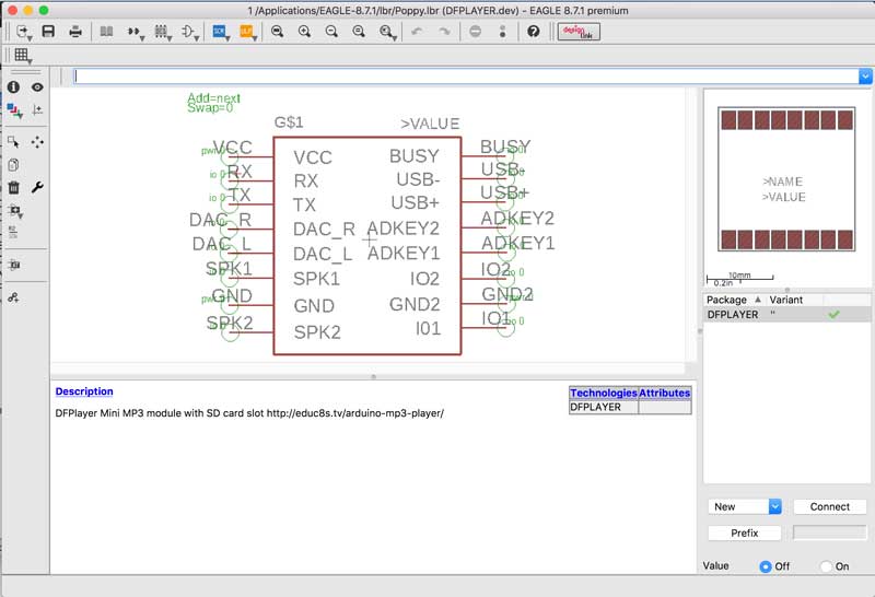
Creating the PCB footprint for the DFPlayer in Eagle
Most of the components used in this project are included in the Eagle library of components, but the DFPlayer Mini was not. So I learnt how to add to the library and it was easier than I imagined.
I followed the instructions at the links below:
Part 1 - Creating a Package
Part 2 - Creating a Symbol
Part 3 - Creating a Device
Eagle Schematic
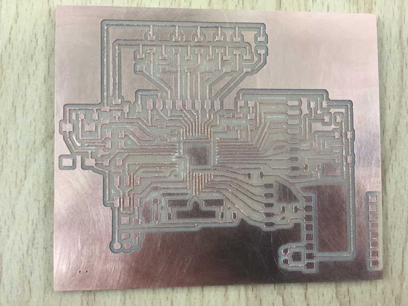
Step 3 Mill the Circuit Board
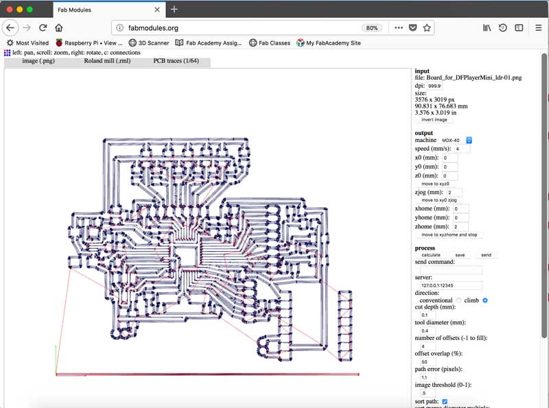
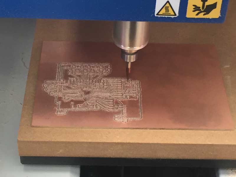
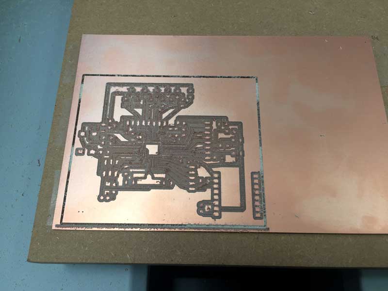
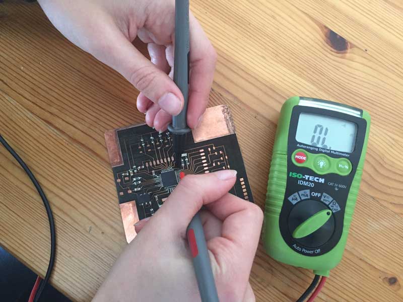
Following the processes in the previous electronics weeks, I milled the circuit board. However this time the finish wasn't as neat, see above, and some of the copper that was supposed to have been removed was still attached at the edges so I scrubbed it with a Brillo pad to remove them. It was hard to know how much pressure to use because some of the traces seemed fragile, but it required a lot of force before it was clean enough to solder, see below.
Step 4 Attach the Electronics to the Circuit Board
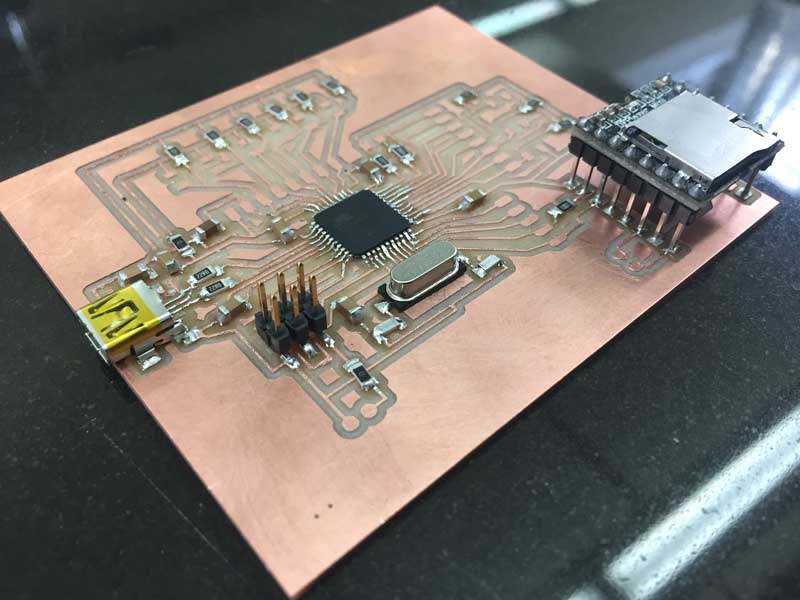
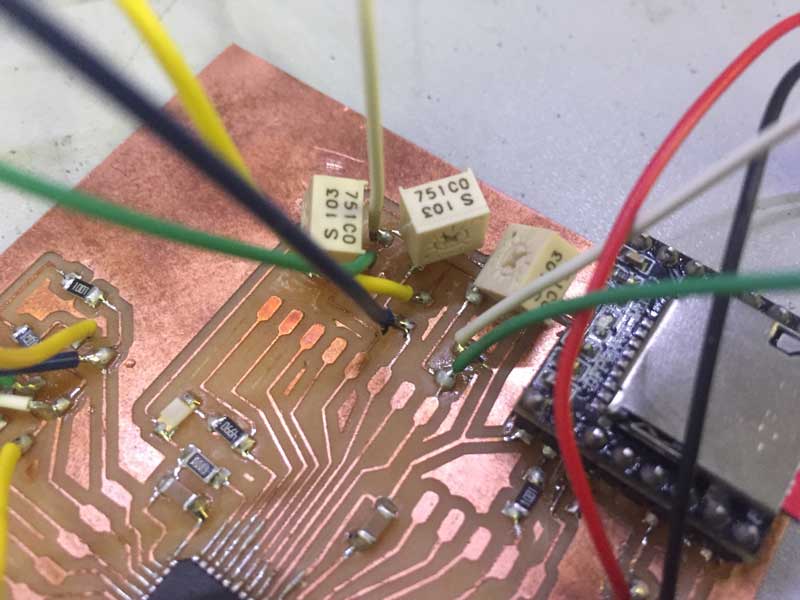
Soldering the micro controller onto the board was tricky as some of the pins got soldered together. I found a heat gun and a blade were the easiest way to separate them. I soldered the other components on and checked for continuity with a multimeter. When I added 10k ohm Potentiometers, shown below, for the LDR's on the digital pins, the board stopped working. So I removed them and worked with just 6 analogue pins. The analog and digital pins might need separate grounds.
Step 5 Boot-loader
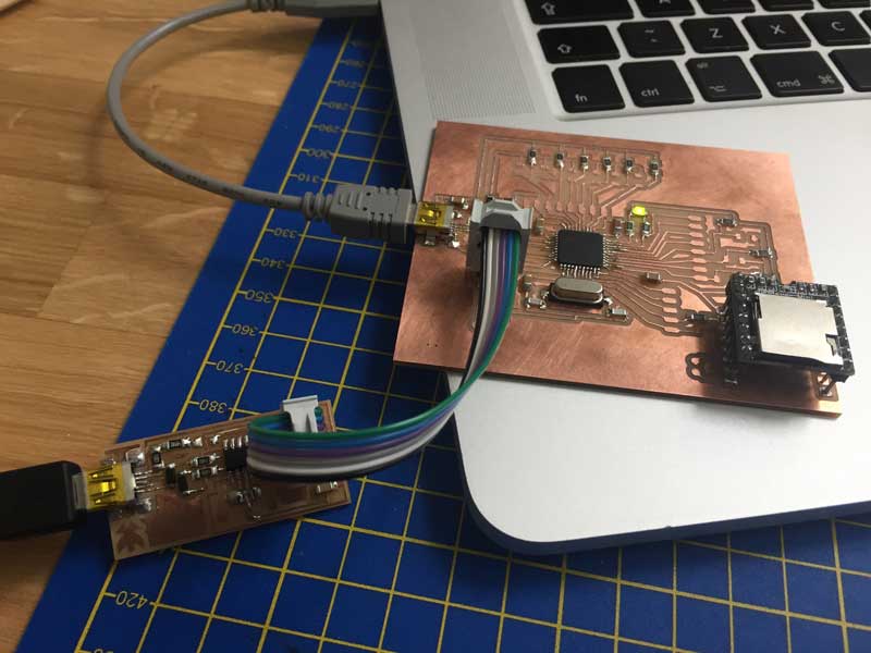
- Using the FabISP made during Week 5, connect the 6 pins on both boards using a ribbon cable. Plug both boards into seperate USB ports on the computer to provide power.
- Open Arduino IDE
- Go to Tools > Board > Arduino Leonardo
- Go to Tools > Programmer > USBTinyISP
- Go to Tools > Burn Bootloader
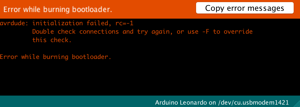
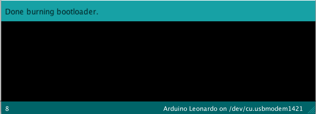
- Look at the bottom of the Sketch window to check progress. When it works it will say "Done burning bootloader." If there is an error message, check the board for shorts and missed connections using a multimeter (called testing continuity aka beep mode). I found I had a short where solder had connected two traces, and the ribbon cable on the ISP was the wrong way round. Once I'd sorted these, bootloading was successful. It was a relief to have found the issues after just a few attempts of troubleshooting.
- The onboard LED lights up when Bootloading has been successful
Step 6 Code and Upload
//This code has been written based on the PlayMP3 sketch from the DFPlayer Mini MP3 by Makuna library and TechPonder'LDR streetlight Instructable.
//
//The number audio files are stored on the SD card with the following names:
//
// sd:/mp3/0001.mp3
// sd:/mp3/0002.mp3
// sd:/mp3/0003.mp3 etc

int sensorPin5 = A5; // select the input pin for the LDR
int sensorPin4 = A4; // select the input pin for the LDR
int sensorPin3 = A3; // select the input pin for the LDR
int sensorPin2 = A2; // select the input pin for the LDR
int sensorPin1 = A1; // select the input pin for the LDR
int sensorPin0 = A0; // select the input pin for the LDR
int sensorValue5 = 0; // variable to store the value coming from the sensor
int sensorValue4 = 0; // variable to store the value coming from the sensor
int sensorValue3 = 0; // variable to store the value coming from the sensor
int sensorValue2 = 0; // variable to store the value coming from the sensor
int sensorValue1 = 0; // variable to store the value coming from the sensor
int sensorValue0 = 0; // variable to store the value coming from the sensor */
int led = 13;

#include <SoftwareSerial.h>
#include <DFMiniMp3.h>

// implement a notification class,
// its member methods will get called
//
class Mp3Notify
{
public:
  static void OnError(uint16_t errorCode)
  {
    // see DfMp3_Error for code meaning
    Serial.println();
    Serial.print("Com Error ");
    Serial.println(errorCode);
  }

  static void OnPlayFinished(uint16_t globalTrack)
  {
    Serial.println();
    Serial.print("Play finished for #");
    Serial.println(globalTrack);
  }

  static void OnCardOnline(uint16_t code)
  {
    Serial.println();
    Serial.print("Card online ");
    Serial.println(code);
  }

  static void OnCardInserted(uint16_t code)
  {
    Serial.println();
    Serial.print("Card inserted ");
    Serial.println(code);
  }

  static void OnCardRemoved(uint16_t code)
  {
    Serial.println();
    Serial.print("Card removed ");
    Serial.println(code);
  }
};

// instance a DFMiniMp3 object,
// defined with the above notification class and the hardware serial class
//
//DFMiniMp3<HardwareSerial, Mp3Notify> mp3(Serial1);

// Some arduino boards only have one hardware serial port, so a software serial port is needed instead.
// comment out the above definition and uncomment these lines
SoftwareSerial secondarySerial(3, 2); // RX, TX
DFMiniMp3<SoftwareSerial, Mp3Notify> mp3(secondarySerial);

void setup()
{
  // initialize the LED pin as an output:
  pinMode(led, OUTPUT);

  Serial.begin(9600);

  // mp3_set_serial (mySerial);  //set softwareSerial for DFPlayer-mini mp3 module

  Serial.println("initializing...");

mp3.begin();
}


void loop() {

sensorValue5 = analogRead(sensorPin5);
sensorValue4 = analogRead(sensorPin4);
sensorValue3 = analogRead(sensorPin3);
sensorValue2 = analogRead(sensorPin2);
sensorValue1 = analogRead(sensorPin1);
sensorValue0 = analogRead(sensorPin0);

Serial.println(sensorValue5);
Serial.println(sensorValue4);
Serial.println(sensorValue3);
Serial.println(sensorValue2);
Serial.println(sensorValue1);
Serial.println(sensorValue0);

if ((sensorValue5 > 50) && (sensorValue5 < 80)) {
    // play track 3:
    Serial.println("track 3");

  mp3.playMp3FolderTrack(3);  // sd:/mp3/0003.mp3
  delay(2500);
  // turn LED on:
    digitalWrite(led, HIGH);
  } else {
    // turn LED off:
    digitalWrite(led, LOW);
  }

if ((sensorValue4 > 60) && (sensorValue4 < 80)) {
    // play track 4:
    Serial.println("track 4");

  mp3.playMp3FolderTrack(4);  // sd:/mp3/0004.mp3
  delay(2500);
  // turn LED on:
    digitalWrite(led, HIGH);
  } else {
    // turn LED off:
    digitalWrite(led, LOW);
  }

 if ((sensorValue3 > 50) && (sensorValue3 < 80)) {
    // play track 3:
    Serial.println("track 5");

  mp3.playMp3FolderTrack(5);  // sd:/mp3/0005.mp3
  delay(2500);
  // turn LED on:
    digitalWrite(led, HIGH);
  } else {
    // turn LED off:
    digitalWrite(led, LOW);
  }

if ((sensorValue2 > 50) && (sensorValue2 < 80)) {
    // play track 2:
    Serial.println("track 2");

  mp3.playMp3FolderTrack(2);  // sd:/mp3/0002.mp3
  delay(2500);
  // turn LED on:
    digitalWrite(led, HIGH);
  } else {
    // turn LED off:
    digitalWrite(led, LOW);
  }

if ((sensorValue1 > 50) && (sensorValue1 < 80)) {
    // play track 8:
    Serial.println("track 8");

  mp3.playMp3FolderTrack(8);  // sd:/mp3/0008.mp3
  delay(2500);
  // turn LED on:
    digitalWrite(led, HIGH);
  } else {
    // turn LED off:
    digitalWrite(led, LOW);
  }

if ((sensorValue0 > 50) && (sensorValue0 < 80)) {
    // play track 7:
    Serial.println("track 7");

  mp3.playMp3FolderTrack(7);  // sd:/mp3/0007.mp3
  delay(2500);
  // turn LED on:
    digitalWrite(led, HIGH);
  } else {
    // turn LED off:
    digitalWrite(led, LOW);
  }
}
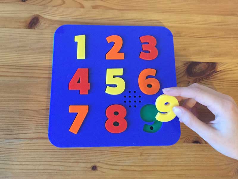
When the pieces are inserted into the holes the light dependent resistors register the level of darkness and trigger the relevant MP3 file to say the right word. One of the issues with the code was that when the numbers remained in the holes the words kept being repeated. I have updated the code so it responds as it goes to light to dark or dark to light and is quiet when it is completly dark or completly light. This overcomes the problem of it repeating the words when the puzzle pieces are in places and has the advantage of saying the word as the pieces are taken out as well as put in.
The additional code:
if ((sensorValue0 > 50) && (sensorValue0 < 80))Step 7 Testing
The milled board worked, but the speaker had a loud crackle which made it difficult to hear the words. Having tried replacing the speaker, checking continuity etc. I took off all the components and rebuilt it. Unfortunately this time the speaker stopped working altogether. I built it on a breadboard and it worked, so I laser cut a new circuit board, using the same PNG file as the milling machine.

The laser cutter was quicker than milling and produced a cleaner board that didn’t need scrubbing. It was etched horizontally, then vertically several times, and I stopped the machine when the black part of the board showed through where the copper was removed.
Due to illness I had to work from home, so I haven’t used the new board. Instead, I soldered all the LDR's to a common ground on my milled board to have something finished by the deadline.
In the next version I will add another positive and ground to the board so that I can have another option for orientating the board.
Step 8 Design and 3D Print Battery Holder
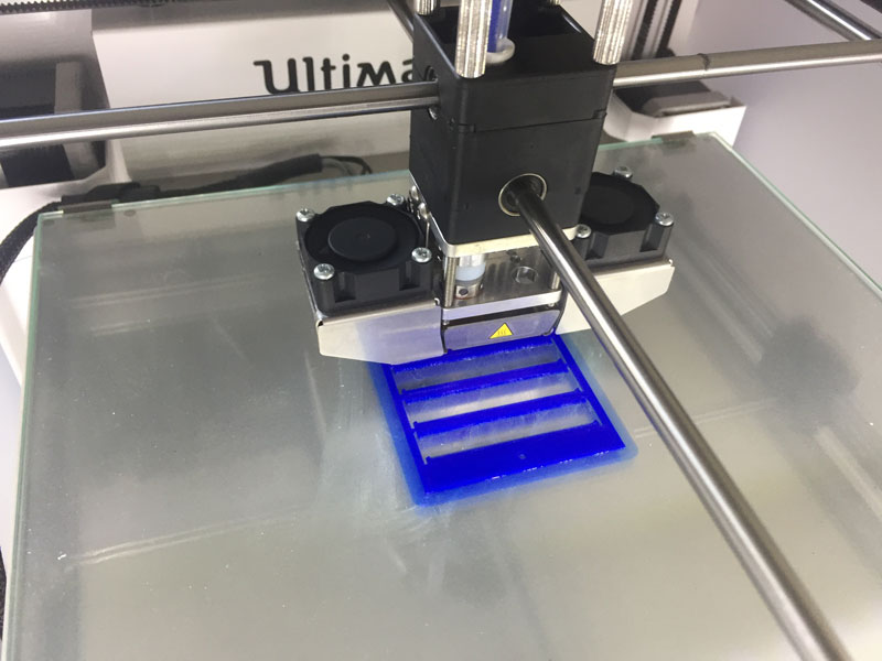
I’ve used 3 AAA batteries in series to power the board, because the depth of the battery holder determines the overall thickness of the game board, and it needs to be kept to a minimum. I’ve recently found out about AAAA batteries, so the next version of the game might be thinner. 6 layers would be lighter, cheaper, easier to hold and close to the golden ratio.
The 3D printed part of the battery holder is designed without a solid base or a top. It doesn’t need them because it’s sandwiched between 2 pieces of laser cut acrylic and a hole in the acrylic can be screwed into the 3D printed part to act as a lid.
The holes for the 3mm screws are 2mm wide because PLA is soft enough to tap the thread by inserting the screws using a screwdriver.
Battery connectors are going to be inserted at the ends of the battery, so a 1mm space was made to fit them. They also need 1mm clearance for wires to be soldered to them, but not across the whole gap because the contacts would be loose. So there are 1mm posts.
Without a solid base, the walls that separate the batteries would not be held in place, so they need a small attachment at the ends to keep them parallel when gluing it to the green acrylic layer. They also have an extra 1mm wide 1mm high layer each side of the walls that separate the batteries, just to make a wider surface area for gluing.
The outline of the battery holder is etched onto the green layer of acrylic during laser cutting, along with plus and minus symbols to indicate the polarity of the batteries. They were legible, but less noticeable once the battery holder is in position, so I drew on them with a black marker pen and wiped off the excess. The black shows up well.
Working parametrically made it easier to make changes. This was particularly useful when I wanted to add 2mm to the length of the case because I hadn’t created enough space for the wires attached to the contacts.
Step 9 Assembly
I used heat shrink to cover the bare wires on the LDR's and attached numbers to make it easier to put the LDR's in the correct holes.
I glued the top 2 acrylic boards together, and placed books on top while drying.
I used a black marker pen on the etched + and - symbols to indicate the battery orientation, see video below, and glued the battery case, lining it up with the outline on the green board.
I glued the bottom 5 acrylic boards together and glued the other components in position.
Then I joined the battery wires to the switch and the ground on the circuit board.
I glued the top boards to the bottom boards, inserted batteries and screwed on the lid of the battery case.