Final project

A device to play music from physical media.
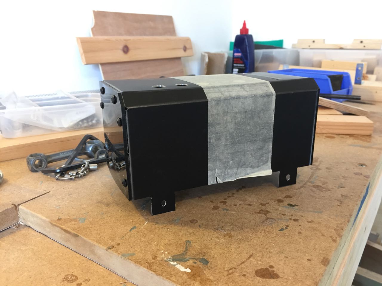
Housed in an industrial-style folded aluminium case.
Contents
- Functionality overview
- Microcontroller board
- SD card reader and MP3 playback
- Media cards and album selection
- OLED Screen and buttons
- SD card reading and MP3 decoding
- File and directory structure
- Media card reading
- Playback controls
- Display
Improvements, lessons learned and next steps
Main Systems
The project is split into several discrete systems. This allowed me to solve problems independently, and complete parts of the overall project in steps. It also gave me flexibility when physically arranging the parts in the case, and determining the overall physical design.
It also introduced a lot of complexity in routing signals and arranging boards. Now I’ve figured out how to make this, for a second version, I would integrate the systems as much as possible onto one board and one mechanical assembly.
Functionality overview
- Music files are stored on an SD card with each alum or playlist in a separate directory. Each directory has an identification number.
- The user inserts cards into the device, and holes in these cards are read, and translated into a number which correlates with a specific directory on the SD card.
- Buttons allow the user to play the MP3s in the directory corresponding to the card inserted, as well as pause, and skip forward and back in the album.
- Actions and status are displayed on the screen
Album selection is only by the use of the media cards. The storage of files on an SD card is invisible to the user (once the card is loaded with files)
Microcontroller board
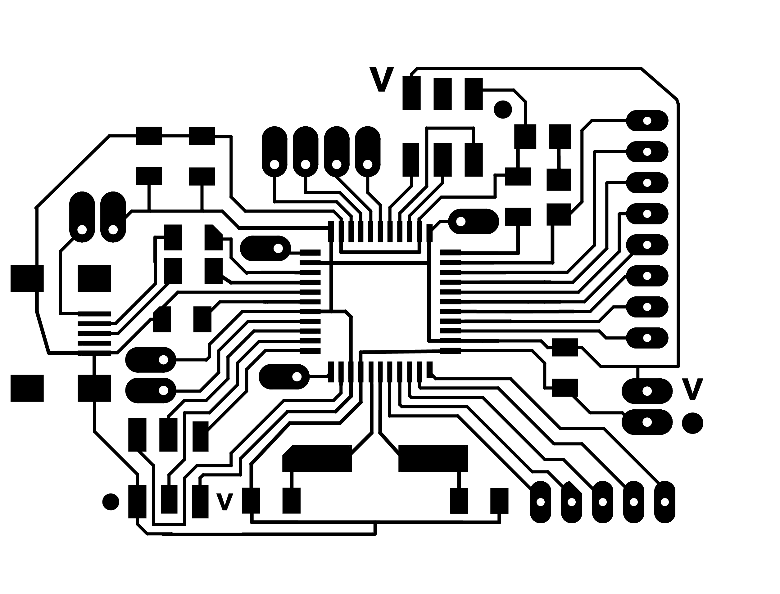
I’m using a board based on the Atmel ATMega 32u4 chip. This gives me plenty of I/O pins, and built-in USB functionality for programming and power. Early versions of this design needed lots of analogue inputs and interrupt pins which this chip also provides. I created a spreadsheet to help me figure out which pins I needed for the functionality required, and how I could swap around pins to let me route traces most easily.
Originally I attempted to integrate the MP3 player board onto this main board, but the routing proved too difficult, so I settled on a design that exposes as many pins as possible in convenient arrangements for my other boards, and takes all the remaining pins out to headers so they can be connected in flexible ways, as my needs change during software development.
For the core chip components (e.g. USB, timing crystal and decoupling capacitors) I derived my design from Luiz Bueno’s Bueno Board V2.

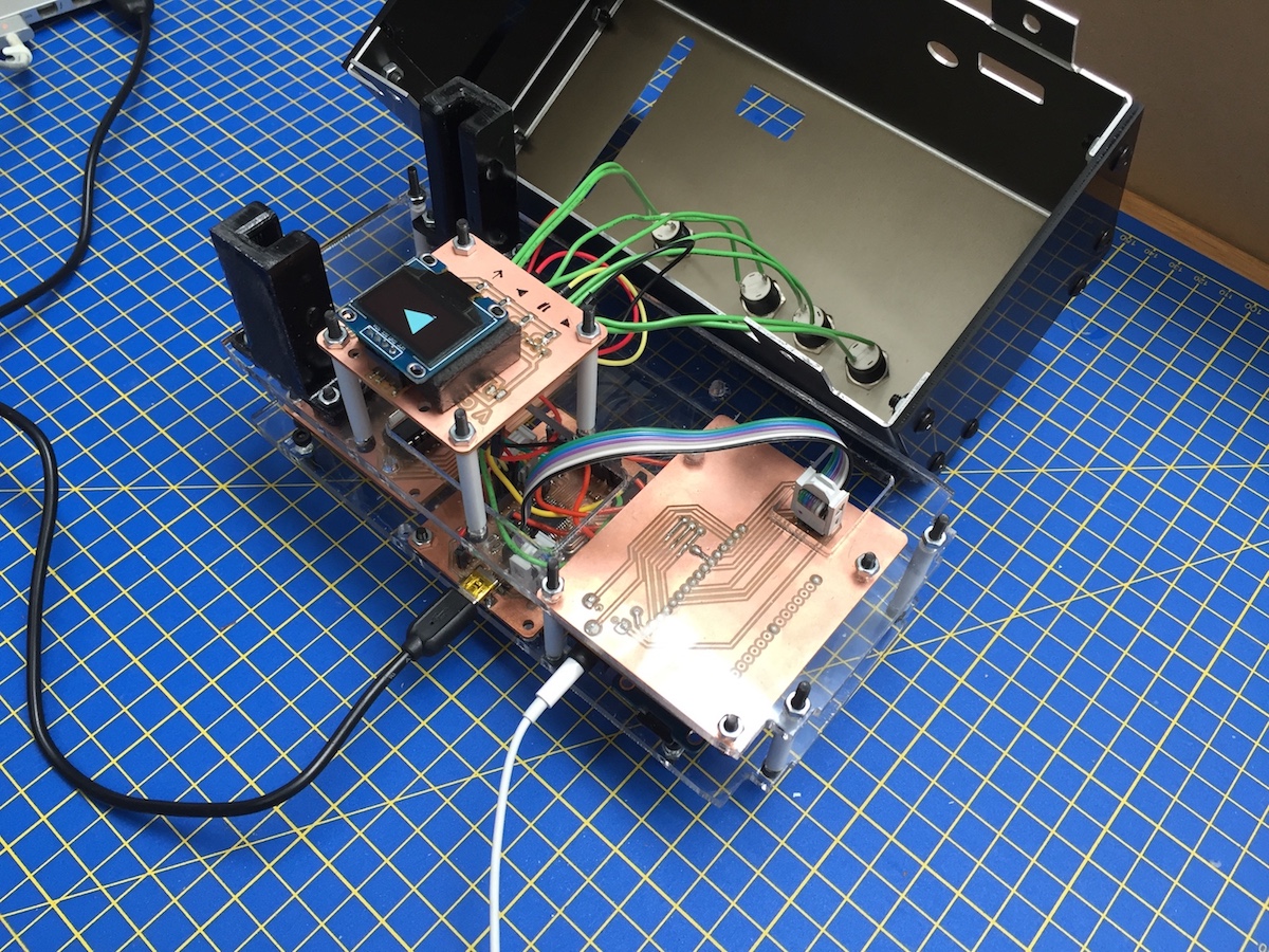
Above, the main board while I was soldering on components. The photo below show the finished main board on the left, connected to my media reader board via a 2x3 header and ribbon cable.

This cable takes power to that board, and also signal to/from the data, latch and clock pins of the shift register.
There is a second 3x2 header near the USB port that does a similar job (for power and SPI connection) to the separate MP3 board.
The red jumper here allows me to add a power switch to break the 5V in from the USB port.
The diagram below shows how all pins are using in the production version.

SD card reader and MP3 playback
I’m using a breakout board from Adafruit https://www.adafruit.com/product/1381 to handle the playback of MP3s from an SD card. This is based on the VS1053 chip http://www.vlsi.fi/en/products/vs1053.html, and is one of many boards that provide this functionality. The board integrates a micro SD card reader, the VS1053 ship for audio decoding and a headphone level output.
It communicates with the main microcontroller board over SPI.
To simplify wiring within the case, I fabbed another board to house the Adafruit board and headphone jack, and to route the wires needed to more convenient locations for connecting to the main microcontroller board.

These photos show an early version of that board. The female headers accept the Adafruit board. Audio signals are routed to the audio output socket. SPI and power are routed to a 3x2 header which plug in via ribbon cable to the ISP header on the main board. Other pins needed for the Adafruit board to work are routed to convenient places where wires are soldered and then connected to headers on the main board.
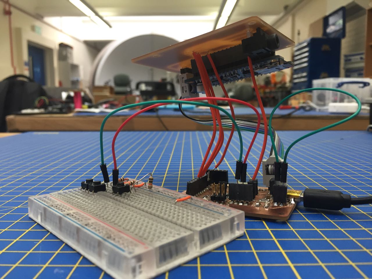
This picture shows how the two boards are connected while in testing.
Media cards and album selection
The media cards work like punchcards with a series of holes aligned along one edge which either block or allow light to pass through at each of 8 points. These points match up with a series of photo interrupt switches which detect whether infrared light is passing between the diode on one side of the switch, and sensor on the other.
Each switch returns a high or low analogue signal, which can be converted to an 8-digit series of 1s and 0s. This can be converted to a decimal number from 0-255, which gives the devices a maximum playback ‘capacity’ of 256 albums.
In prototyping, I tried various ways to read these switches, eventually settling on a PISO (parallel in, serial out) shift register http://www.ti.com/lit/ds/symlink/cd4021b-q1.pdf which is designed to do exactly this task in hardware, allowing me to simplify my code, and also reduce the number of inputs needed from 8 analogue inputs, down to three digital I/O pins. I think this is one of the most elegant features of the project.
Cards are inserted through a slot in the top of the case, and guided into position by two sets of fingers mounted on the internal chassis. These are cast from resin. I modelled them in Fusion 360, then modelled a pre-mold to mill out of wax.


This model shows the final design, modelled into a box to cast the silicon mould. The box has tapered edges to allow the drill bit access as it widens out after the initial 15mm shaft.

I used Oomoo 25 two-part silicone compound to make the mold, and Smooth-Cast 326 two-part resin with some black dye to make the part. You can see from the picture below that the mold is only one part, leaving an imperfect finish on the top surface of the resin. However this face isn’t important for the function of the part, so I wasn’t too concerned about this.

After I’d cast both sets of fingers, I smoothed the functioning surfaces with some 320-grit sandpaper and drilled mounting holes in the bases. You can see from the picture below that air bubbles in the silicone mold caused imperfections in the surface of the parts. This was caused by the exothermic curing of the resin heating the mold and causing the air bubbles to expand. However, these were not present on the guiding surfaces of the fingers, so not a problem in this case, as the parts will not be visible.
The media cards which ‘store’ the albums are made from 5mm black acrylic. After many hours of troubleshooting, I discovered that some of the opaque acrylic we have in the lab is not in fact opaque to infrared light. After substituting acrylic from another supplier, I was able to get these to work. I experimented with laser settings to get the best finish, eventually cutting at 5% speed, 100% power, 5kHz frequency.
Even with these settings, a slight burr was left on the cut edge of the acrylic, which I removed with sandpaper. I then applied a matte finish to each card by sanding the flat surfaces in a regular pattern with very fine (1200-grit) sandpaper.

OLED Screen and buttons
The intention for this device is that the user interface is very simple, and control is primarily through the insertion of media cards. However, some playback controls are useful. On the top are buttons to initiate reading of the card (also starting playback) pause or resume, and skip forward and back one track in the album.
I had originally hoped to use Cherry MX mechanical switches to make controls but I didn’t have time to make or source keycaps, so I bought small momentary panel mount buttons for this version. These are far from ideal, but do the basic job OK. Output is to an existing amplifier and speaker setup, so no volume control is needed on the device.
The OLED screen provides simple confirmation of actions, showing play, pause or skip indicators, as well as prompting the user to insert a media card to start. At this stage, no MP3 metadata is extracted to show which song is playing. (GND, VCC, SDA, SCL) are needed to attach it to the main board.
I made another small breakout board so I could mount the OLED panel just behind the top of the case, and also provide an easy attachment point for the button leads. These photos show the board before and after soldering.

The buttons are mounted to the external case, with nuts accessed from behind the panel. So they must be fixed to the case before the rest of the components are inside. That means they need long flying leads which can be wired to the main board. This is not ideal, and in a future version I would like to use components which are all mounted to one chassis, with a case added afterwards.
This photo show green leads from the panel mounted buttons going to a small breakout board that handles buttons and the OLED screen.

Construction
Internal chassis
WIth 4 boards, a screen and buttons, a media slot, and access needed to USB, SD card and audio out, I needed some way of holding all the components in place, so they were stable, secure, and in definable positions. Then I would be able to make an external case with holes in the right places, and also attach all the parts to the case. This proved to be far harder than I had expected.
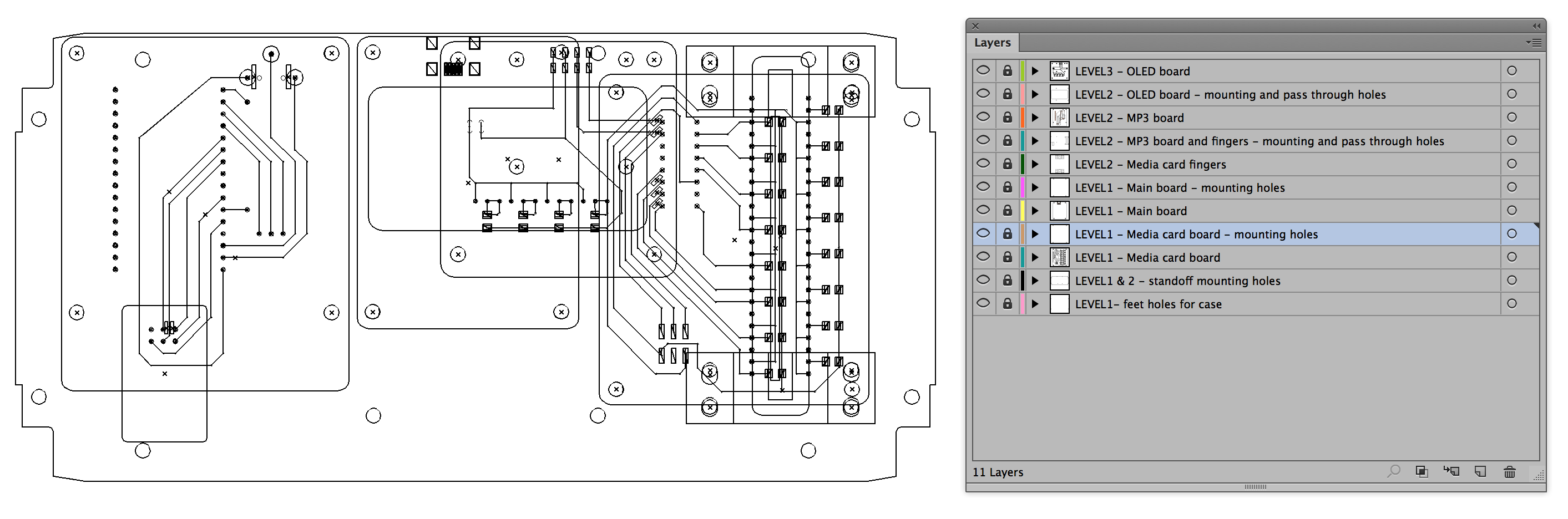
I started by modelling a few options for board layout in Fusion 360, before settling on a chassis made from a series of levels separated by standoffs. In this way, I could mount user controls on the top surface, create space for media cards to be inserted, and hold all the boards in fixed relative positions.
I already had DXF files for all the boards I’d made, as part of the board design process, so I imported these into Illustrator to do 2D layout of each level of the chassis. I marked placement of mounting holes for each board, and pass-through holes in each layer where cables need to run between levels. I also marked holes for screws in the base plate that could be attached to tabs in the case to hold the case and chassis together.
In the course of designing the chassis, I also had to take account of problems which arose in the production of the board, all of which I redesigned in this time, as well as considerations for the fitting of the case and placement of holes for access to the ports. So this was a very iterative process, with many fine adjustments need to ensure the chassis fit into the case, that components were at the right heights, that cables could pass freely, and that the whole thing could be assembled.
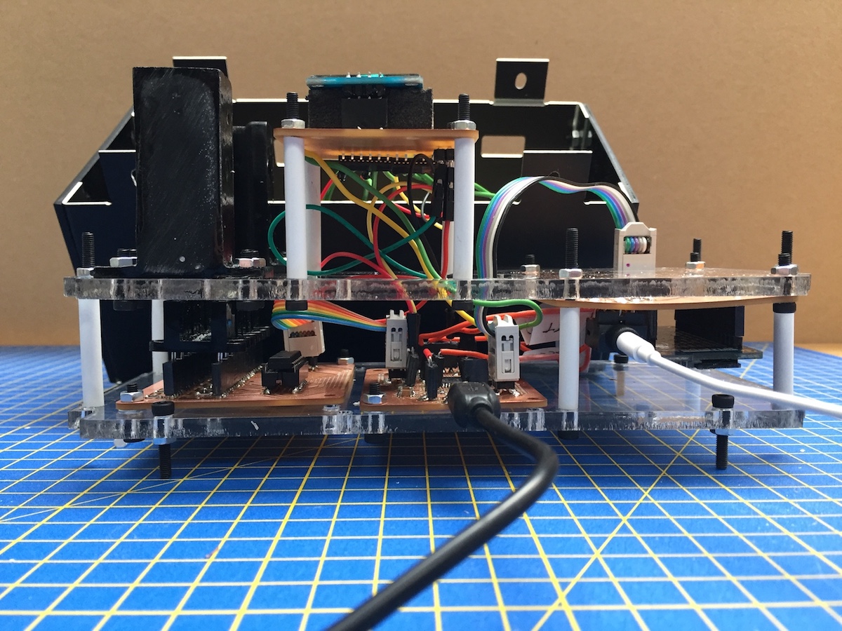
For the final chassis, I used 5mm clear acrylic for strength and visibility to aid wiring. I cut standoffs from styrene modelling tube, and assembled the whole chassis with 3mm machine screws.
### External case
From day 1, it was always important that this project had a well-finished case. I want it to look like a piece of industrial equipment, or something from a spaceship, not something with a typical makerspace aesthetic, typical of laser-cut play, or 3D-printed shells.
I wanted to use metal, and the easiest to work with given the tools available was aluminium. I ordered some anodised 1.2mm thick aluminium sheets, cut to the size of our milling machine bed (300 x 400mm).
I’d done some tests scoring and cutting aluminium during wildcard week, so I was pretty confident I could make a folded metal case. Using my (evolving) chassis designs as a template, I worked out the overall dimensions, and placement of access holes and the front and rear of the case.
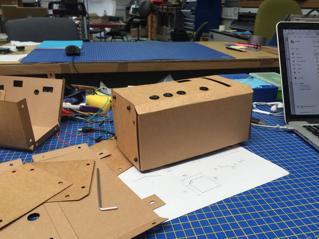
I laser-cut prototypes from thin card and used these to test fit my chassis and top panel components.

Once I was happy with the design, I created a version specifically for milling aluminium. The score lines for folding were drawn as 3.1mm thick lines. This would allow me to mill the scoring pattern with a 3mm bit, which is robust enough to stand up to this treatment.
I would use the same bit for cutting out the holes and external outline, so I needed to adjust the design to allow extra clearance around sharp internal corners, such as those on the fold-over tabs.
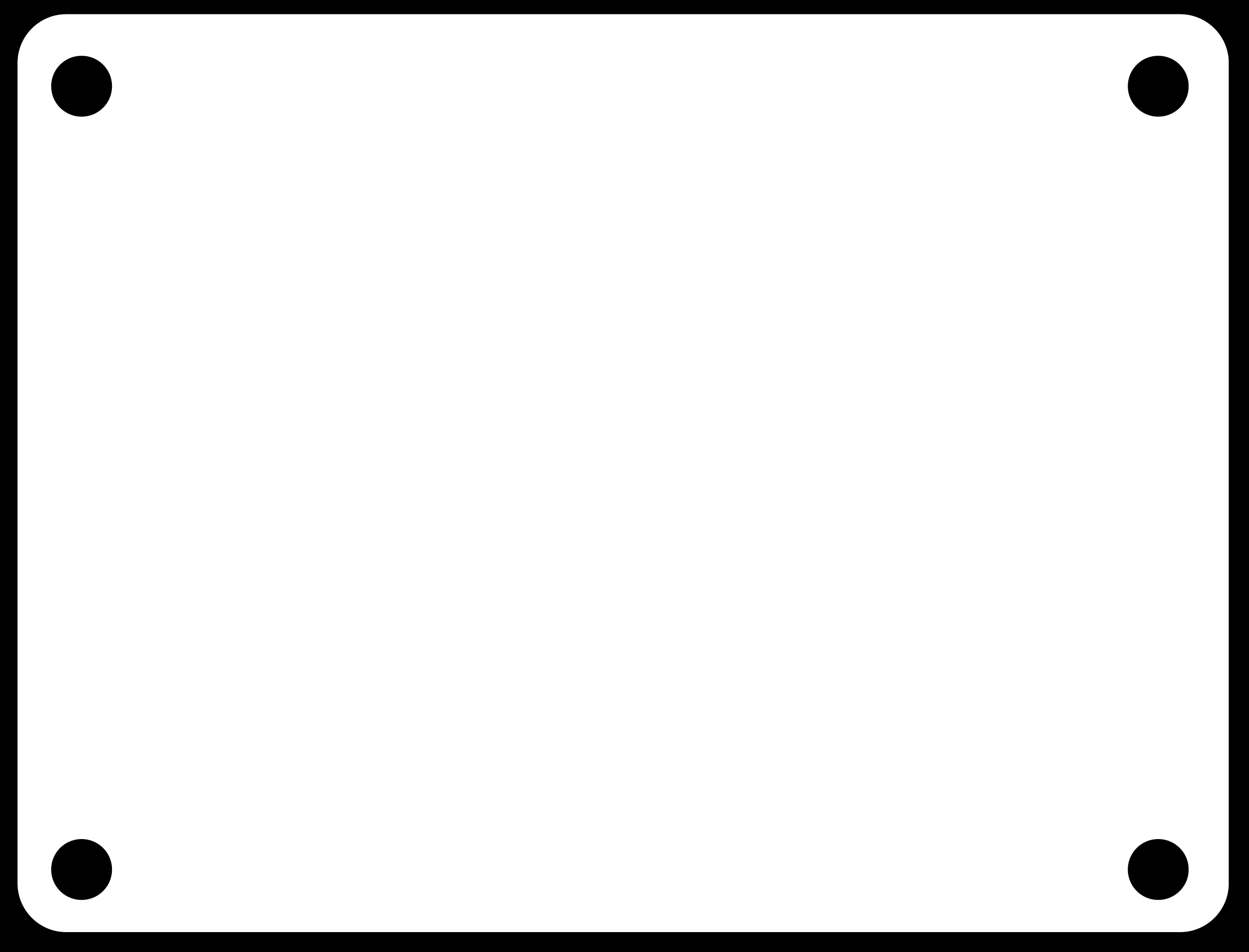
These images show the outline shape, and the score line shapes.

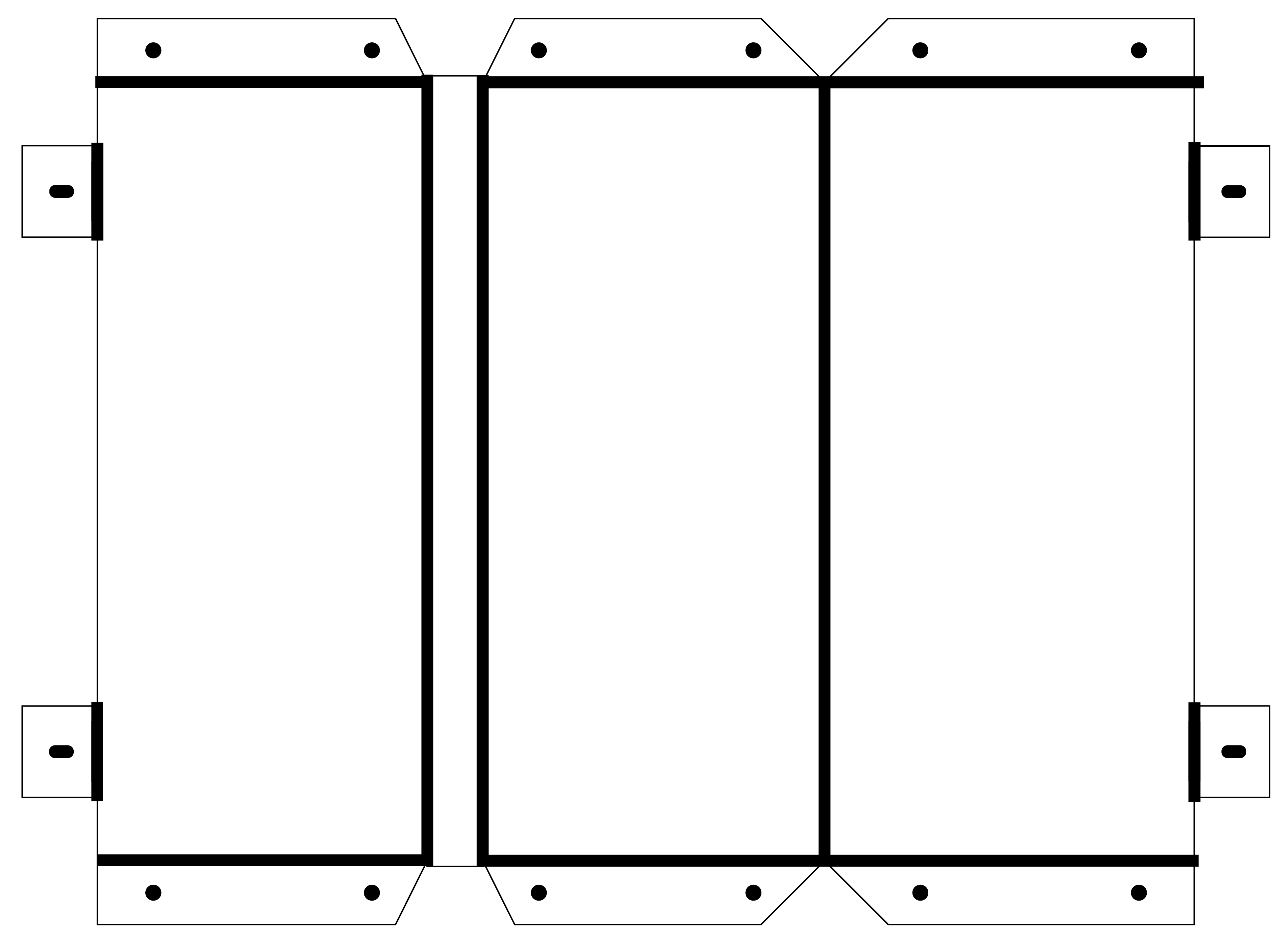
Both were converted into cutting paths using a the ‘PCB outline’ mode in Fab Modules. For the scoring, I set the material depth to 0.4mm (the depth of the score line I wanted, with a very conservative step depth of 0.2mm. For the outline, I changed the cut depth to 1.2mm, but otherwise the processes were the same.


When cutting, I used a high spindle speed (15,000 RPM) and a slow X/Y movement speed, using the override controls on the milling machine to reduce this down to about 30% of the programmed speed (4mm/sec).
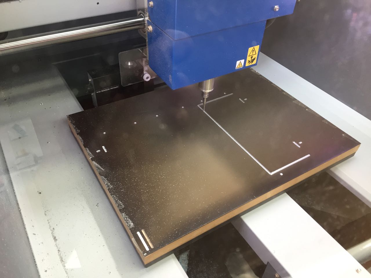
The scoring pass took about an hour, with another 3-4 hours for the outline pass. As the picture below shows, this wasn’t quite deep enough to cut through the sheet in all places. So I reset the z-index 1mm down and ran this toolpath again until it had made enough passes to cut through the remaining material.
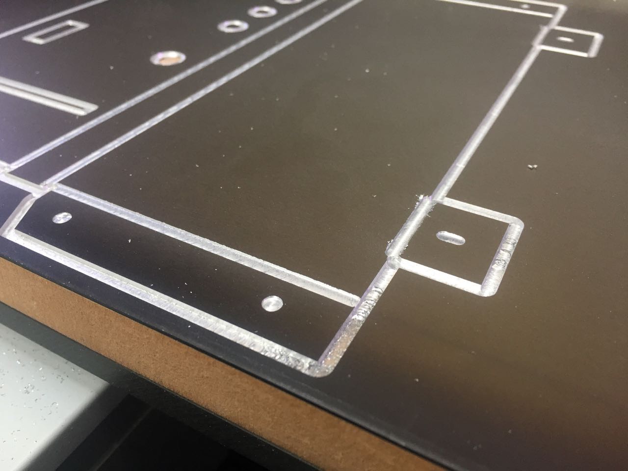
The finished part had a great finish, with only minor cleanup with a file and sandpaper needed on some edges
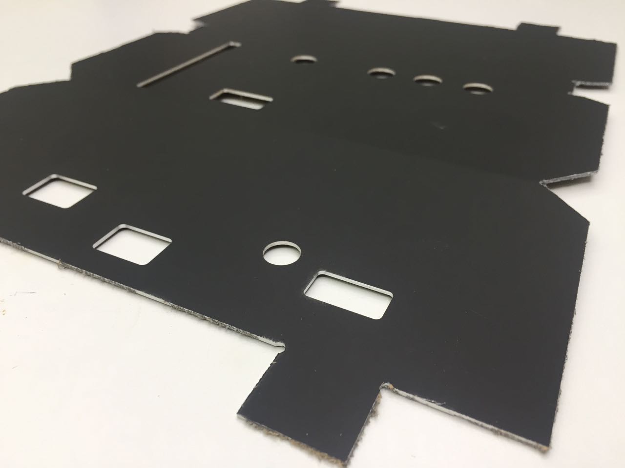
I used a hand drill to complete the holes on the folding tabs (I’d only marked these on the milling machine) and then used a vice and wooden blocks to fold the sheet by hand.

After some adjustment to make sure all angles were correct, the fit was pretty good.

Final assembly
Once I had made the proper aluminium case, I was able to finalise the layout and spacing of the interior chassis, and make adjustments (such as sloping off the corners of the acrylic) to allow it to fit into the relatively inflexible aluminium case.
I used acrylic for the side panels, giving them a matte finish with fine sandpaper to fit in better with the more industrial feel of the metal.
I connected all the remaining ribbon cables and wires between boards, slide the case on top and folded the tabbed feet over to attach to pre-fixed bolts on the base plate. I then covered these in foam pads to give a more forgiving surface for the device to stand on.
Software
Writing the code to drive the device proved to be an enormous challenge, as I had very little experience, even with Arduino, before starting Fab Academy. I spent many days working on some problems, making little headway, where i suspect an experienced programmer could have written this code in an afternoon.
The code is broken down into a few systems:
SD card reading and MP3 decoding
I’m using a library called SFEMP3 (which in turn uses the SDFat library) to interface with the VS1053 chip that handles MP3 playback. https://github.com/mpflaga/Arduino_Library-vs1053_for_SdFat
I had previously tried using the equivalent Adafruit library, but found this to be inflexible and poorly documented. https://github.com/adafruit/Adafruit_VS1053_Library
I’m communicating with the MP3 breakout board over SPI, using the SPI library.
File and directory structure
In this version, I’m using very simple logic to navigate through directories of MP3s on the SD card, and play music. The software assumes all directories will be named 001, 002, 003, etc., and within each, there will be a number of mp3 files, each named 001.mp3, 002.mp3, 003.mp3, etc. This is in part due to a restriction in the library to use DOS-style 8.3 filenames, but also because I was unable to write code to build an array of mp3 filenames with arbitrary names. This is an improvement for version 2.
By setting some variables for the track and album indices, I am able to construct a filepath for each mp3 to be played:
// empty the trackToPlay char array first!
for( int i = 0; i < sizeof(trackToPlay);  ++i )
trackToPlay[i] = (char)0;

// create strings with leading zeroes to hold the album and track numbers
sprintf(albumNumber, "%03d", albumIndex);
sprintf(trackNumber, "%03d", trackIndex);

// construct the file path
strcat(trackToPlay, albumNumber);
strcat(trackToPlay, "/");
strcat(trackToPlay, trackNumber);
strcat(trackToPlay, ".mp3");

// play a file, then increment the track index
MP3player.playMP3(trackToPlay);
trackIndex++;
Media card reading
Each card has a pattern of up to 8 holes which are read by the photo-interrupt sensors, giving a series of 8 analogue values. In earlier versions , I used analogue inputs on the ATMega chip to read these and convert them first to a binary number (like 10011101), then to a decimal number (157), which is used as the album index.
But Michael suggested I could use a shift register to convert these 8 parallel inputs into one serial output. I used the CD4021 chip to do exactly this, so the album identification is handled entirely on that chip. I modified some example code https://www.arduino.cc/en/Tutorial/ShiftIn to read this data from the shift register:
int shiftRegisterReader() {

  //Pulse the latch pin:
  //set it to 1 to collect parallel data, wait
  digitalWrite(latchPin,1);
  delayMicroseconds(20);
  //set it to 0 to transmit data serially
  digitalWrite(latchPin,0);

  //while the shift register is in serial mode
  //collect each shift register into a byte
  albumIndex = shiftinRevised(dataPin, clockPin, LSBFIRST);

  return albumIndex;

}


byte shiftinRevised(byte dataPin, byte clkPin, byte bitOrder) {
  byte shiftvalue = 0;
  //  doing this manually to get around my badly ordered pins

    digitalWrite(clkPin, LOW);
    shiftvalue |= digitalRead(dataPin) << 3;
    digitalWrite(clkPin, HIGH);

    digitalWrite(clkPin, LOW);
    shiftvalue |= digitalRead(dataPin) << 2;
    digitalWrite(clkPin, HIGH);

    digitalWrite(clkPin, LOW);
    shiftvalue |= digitalRead(dataPin) << 1;
    digitalWrite(clkPin, HIGH);

    digitalWrite(clkPin, LOW);
    shiftvalue |= digitalRead(dataPin) << 0;
    digitalWrite(clkPin, HIGH);

    digitalWrite(clkPin, LOW);
    shiftvalue |= digitalRead(dataPin) << 4;
    digitalWrite(clkPin, HIGH);

    digitalWrite(clkPin, LOW);
    shiftvalue |= digitalRead(dataPin) << 5;
    digitalWrite(clkPin, HIGH);

    digitalWrite(clkPin, LOW);
    shiftvalue |= digitalRead(dataPin) << 6;
    digitalWrite(clkPin, HIGH);

    digitalWrite(clkPin, LOW);
    shiftvalue |= digitalRead(dataPin) << 7;
    digitalWrite(clkPin, HIGH);

  return shiftvalue;
}
Because of the pin layout on the shift register, it was difficult to wire all the sensors in the correct order. So I just wired them in the most straightforward way, and then worked out the correct order to read the pins and implemented that manually in the code.
Playback controls
There are only 4 controls:
- Read the inserted media card and start playback
- Pause (or resume) playback
- Skip forward one track
- Skip back one track
The code uses simple logic to modify the track index as the user skips around tracks so that when the playback part of the main loop is executed, it knows which track to play, if an album is finished, or if there are no more tracks available to skip to.
I’m using the Bounce2 library to debounce the buttons.
Display
The OLED panel is connected over I2C, and I’m using the Wire library to communicate with it, and u8g2 library to handle text and bitmap output. https://www.arduino.cc/en/reference/wire https://github.com/olikraus/u8g2
The device doesn’t really need a display, and I’m just using it to show which button has been pressed, along with some simple status messages. In a later version, I would like to do much more with this.
Improvements, lessons learned and next steps
Assembly and construction
The multiple board design – while it allowed me flexibility when I was figuring out how build both the software and hardware – came with a large price. It was very difficult to come up with a simple, robust and elegant way to hold the boards together in a case. Now that I’m confident these components work together, I’m working on a second version of the board that I hope will allow me to integrate all the parts on one board. This would be much more reliable, reduce component cost, and make it easier to replicate.
An important part of the project is the look and feel of the device. I’m pleased with the folded aluminium casing, though I thin this cold be improved perhaps with a two part design, where all the components are mounted to one part of the case, then another independent part is placed on top or around it to complete the casing. The panel-mounted power switch and control buttons make assembling the case very difficult, and necessitate the use of long connecting wires to these components.
The resin guides for the media cards work better than I had expected. I wanted the insertion of the cards to feel nice, like a well-made machine, or a device from the future. The current solution is simple and feels quite solid, but doesn’t have the smoothness I would like. Also, the limit stop (where the card can go in no further) is just the card hitting the crossbars of the photo-interrupt switches. They shouldn’t be performing this mechanical function. I would like to experiment with a mechanical inset and eject system, perhaps using bearings or sprung mechanisms.
The photo interrupt switches are just held in with their contact pins, so could come loose. These should be mounted more securely, and this mounting should likely be integrated with whatever mechanism is used for guiding the media cards into place.
The acrylic media cards are simple, easy to produce in quantity, and with some time spent finishing, have a pretty good look and feel. However, to produce in quantity (this version of the player can handle up to 256 albums) would use a lot of material. It would be interesting to play around with other options, perhaps including card or thin plastic sheet. There also needs to be a simple way of labelling the albums. I feel like this could be quite rough and ready, like cassette tape labelling.
User interface
I had originally hoped to use mechanical key switches like those used on old computers. These kinds of keys are often seen in sci-films. However, I was unable to source keycaps for these switches. Now I’d like to experiment with casting or printing https://www.thingiverse.com/make:131197 keycaps. The current buttons are of very poor quality, and one of the weakest features of the device.
The OLED display is high resolution, and compact, but perhaps too clean for the industrial look I’m going for. I’d like to find an I2C LCD display to use instead, which would be a better size, and also have a grainier fuzzier aesthetic more in keeping with the overall project. It would of course be useful to display track information on the screen.
A volume knob and perhaps an encoder for selecting tracks or albums might also be useful, though the latter would take the project away from one of it’s core premises - that the music is ‘stored’ on the media cards.
### Software
The current software is only minimally functional. I’d like to improve the playback logic so that it can handle less structured directory and file names.
The current sketch uses almost all of the program memory of the 32u4 chip (and 60% of the RAM), which limits my ability to for example, show text on the display. With some help, I might be able to refactor the code to use fewer resources, which would let me build a better screen interface.
Files
Circuit boards
Main microcontroller board
Photo-interrupt sensor and shift register breakout
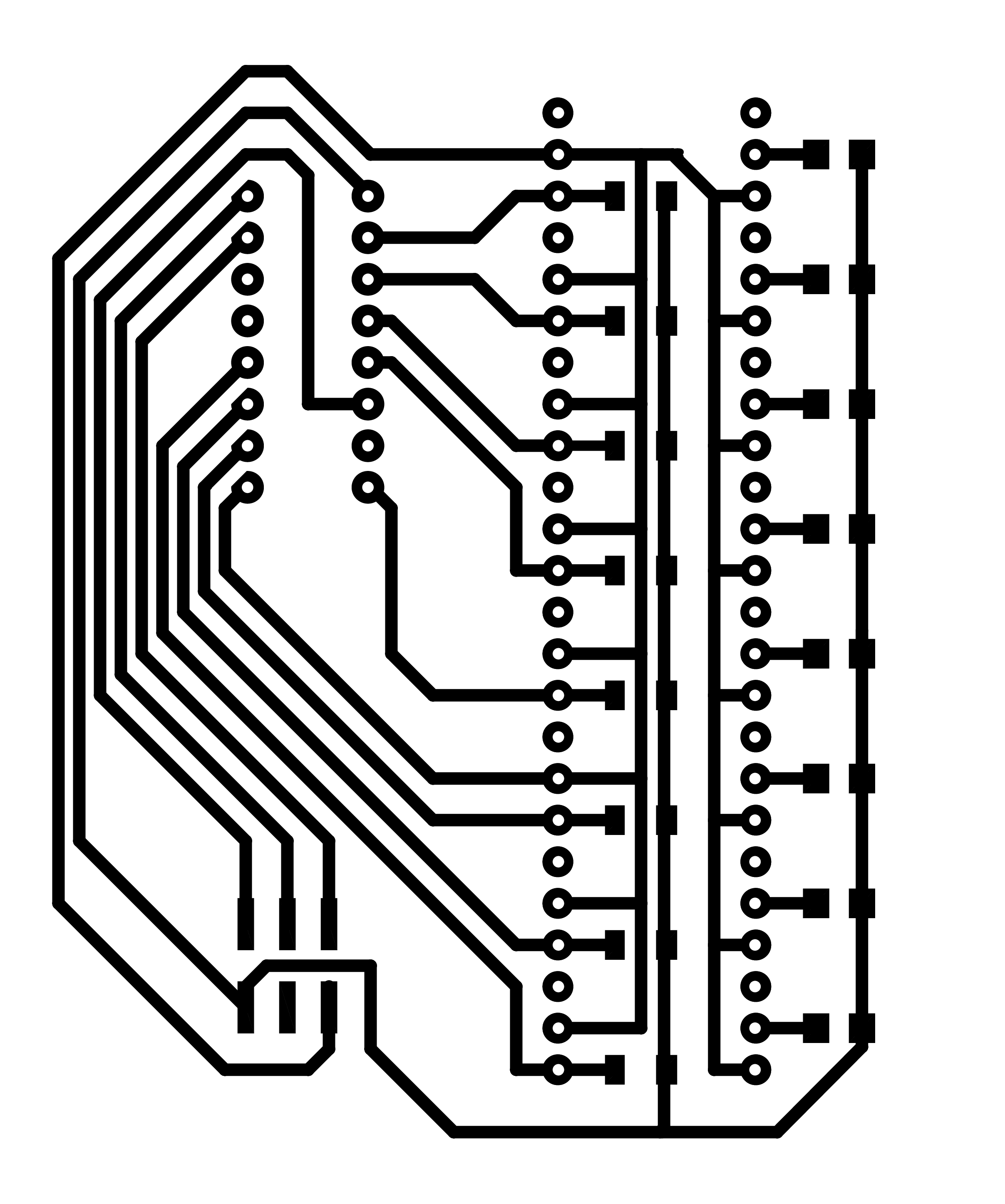
OLED screen and buttons breakout
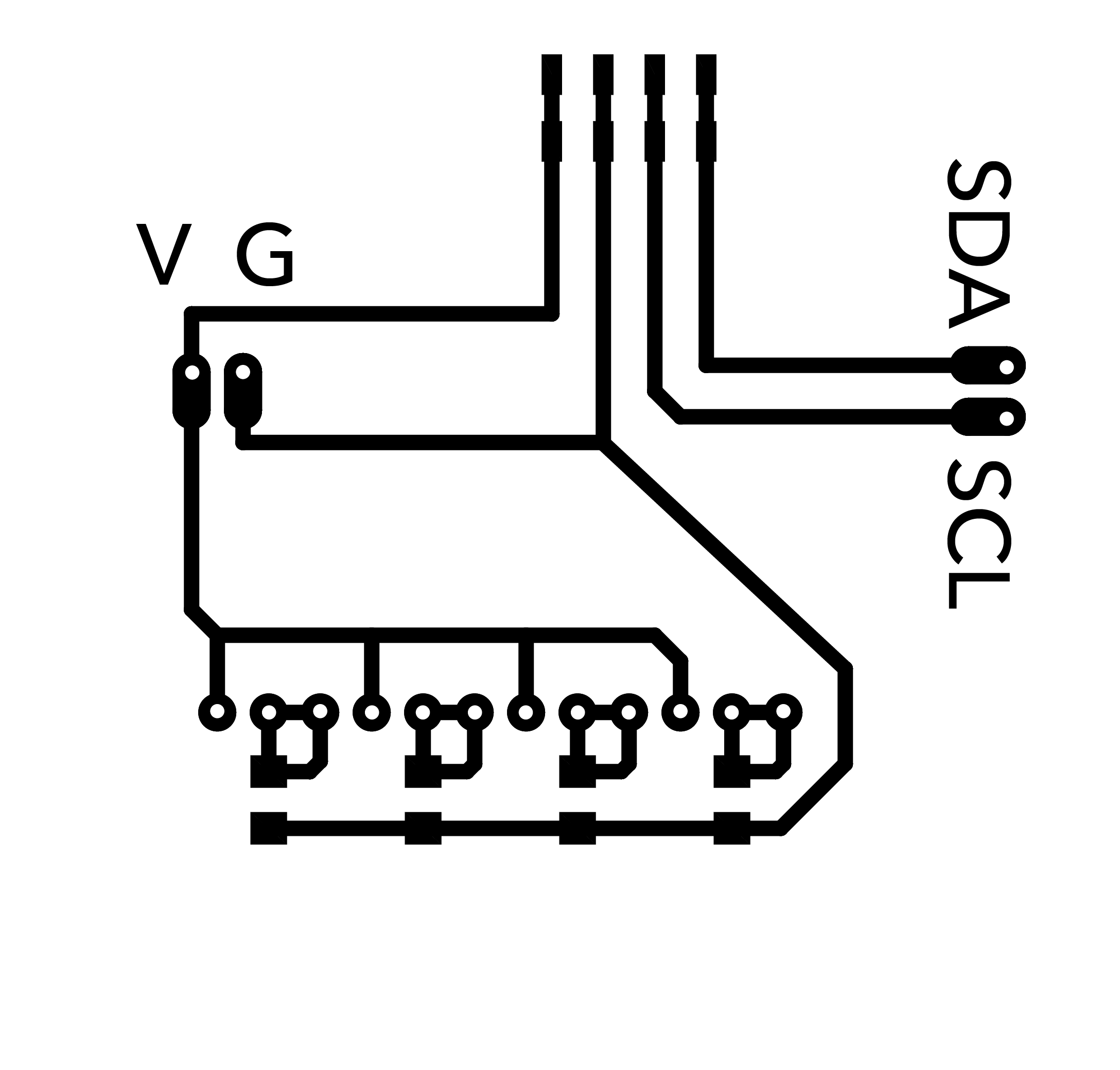
MP3 Player breakout holder
Software
- Arduino file
Physical parts
Chassis
Folded aluminium case
- Illustrator file
- Score lines PNG
- Outline PNG
Acrylic side panels
Media cards
Guide slot
Eagle files for my board
Arduino test files