Final Project Documentation
4. Embeded Programming
Testing sensors
1. HCHO (VOC) sensor
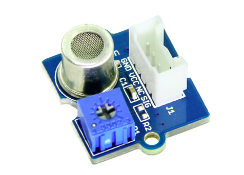
For Data reading of VOC sensor I could use the manufacturer code as to see below. First Code shows the Part 1 of the programming the sensor, which is the calibrating part.
    demo of Grove - HCHO Sensor by seeds studio


    #include              // load the math.h library

    #define Vc 4.95

    #define R0 34.28              // the number of R0 you detected just now

    void setup()                  // At the begining of the programm connect to the serial port
    {
        Serial.begin(9600);
    }

    void loop()
    {
        int sensorValue=analogRead(A1);     // read the signal (voltage value) from the pin A1 (analog)
        double Rs=(1023.0/sensorValue)-1;   // calculate Rs out of the read voltage value of pin A1
        Serial.print("Rs = ");
        Serial.println(Rs);                 // Print the real value of Rs
        double ppm=pow(10.0,((log10(Rs/R0)-0.0827)/(-0.4807)));  // calculate the HCHO level withs this callculation (ppm)
        Serial.print("HCHO ppm = ");        // Print the VOC value
        Serial.println(ppm);
        delay(10000);                        //wait 10 seconds bevor you read the next value
    }
After the calibration, when I was sitting in the garden, there was a car nearby that started the engine. Immediately, even if I did not think about it, the sensor data has risen enormously. A few minutes later, a neighbor started the barbecue and the sensor data went up immediately ...
After the calibration in the outside air, I could bring the sensor into the room and measure the data of the room air. The sensor data kept rising as I was in the room with the door closed and after opening the window, the value of HCHO quickly dropped off.
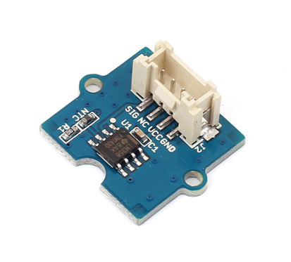
2. Temperature sensor
Grove temperature sensor v1.2 Seeds Studio .
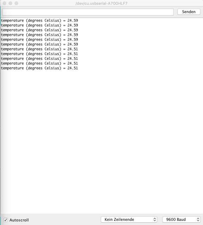
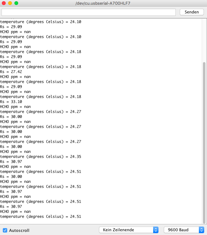
Here you can find the simple temperature and HCHO data reading code:
// Demo code for Grove - Temperature Sensor V1.1/1.2 // Loovee @ 2015-8-26 #include// Following two constants belonge to the HCHO sensor: #define Vc 4.95 #define R0 34.28 //the number of R0 you detected during the calibration const int B = 4275; // B value of the thermistor const int Rinit = 100000; // Rinit = 100k const int pinTempSensor = A0; // temperature sensor connect to A0 void setup() { Serial.begin(9600); } void loop() { int a = analogRead(pinTempSensor); float R = 1023.0/a-1.0; R = Rinit*R; float temperature = 1.0/(log(R/Rinit)/B+1/298.15)-273.15 - 2; // convert to temperature via datasheet int sensorValue=analogRead(A1); // read the signal (voltage value) from the pin A1 (analog) double Rs=(1023.0/sensorValue)-1; // calculate Rs out of the read voltage value of pin A1 Serial.print("Rs = "); Serial.println(Rs); // Print the real value of Rs double ppm=pow(10.0,((log10(Rs/R0)-0.0827)/(-0.4807))); // calculate the HCHO level withs this callculation (ppm) Serial.print("HCHO ppm = "); // Print the VOC value Serial.println(ppm); Serial.print("temperature (degrees Celsius) = "); Serial.println(temperature); delay(2000); }
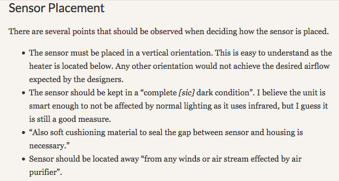
3. Dust sensor
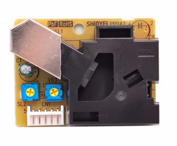
In the following you can find the data reading code for dust sensor from the seedsstudio.com .
int pin = 8;
unsigned long duration;
unsigned long starttime;
unsigned long sampletime_ms = 30000;//sampe 30s ;
unsigned long lowpulseoccupancy = 0;
float ratio = 0;
float concentration = 0;

void setup()
{
    Serial.begin(9600);
    pinMode(pin,INPUT);
    starttime = millis();//get the current time;
}

void loop()
{
    duration = pulseIn(pin, LOW);
    lowpulseoccupancy = lowpulseoccupancy+duration;

    if ((millis()-starttime) > sampletime_ms)//if the sampel time == 30s
    {
        ratio = lowpulseoccupancy/(sampletime_ms*10.0);  // Integer percentage 0=>100
        concentration = 1.1*pow(ratio,3)-3.8*pow(ratio,2)+520*ratio+0.62; // using spec sheet curve
        Serial.print(lowpulseoccupancy);
        Serial.print(",");
        Serial.print(ratio);
        Serial.print(",");
        Serial.println(concentration);
        lowpulseoccupancy = 0;
        starttime = millis();
    }
}
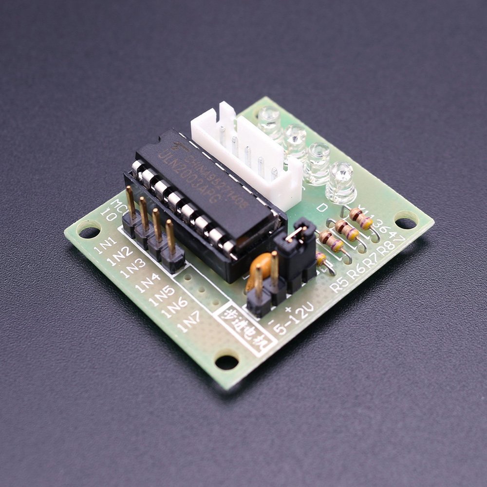
4. Stepper Motor
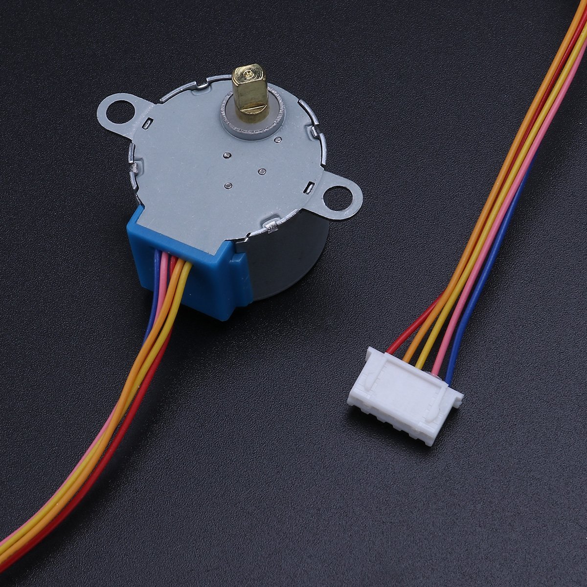
Simple stepper motor code:
    /*
  Stepper Motor Demonstration 1
  Stepper-Demo1.ino
  Demonstrates 28BYJ-48 Unipolar Stepper with ULN2003 Driver
  Uses Arduino Stepper Library

  DroneBot Workshop 2018
  https://dronebotworkshop.com
*/

//Include the Arduino Stepper Library
#include

// Define Constants

// Number of steps per internal motor revolution
const float STEPS_PER_REV = 32;

//  Amount of Gear Reduction
const float GEAR_RED = 64;

// Number of steps per geared output rotation
const float STEPS_PER_OUT_REV = STEPS_PER_REV * GEAR_RED;

// Define Variables

// Number of Steps Required
int StepsRequired;

// Create Instance of Stepper Class
// Specify Pins used for motor coils
// The pins used are 8,9,10,11
// Connected to ULN2003 Motor Driver In1, In2, In3, In4
// Pins entered in sequence 1-3-2-4 for proper step sequencing

Stepper steppermotor(STEPS_PER_REV, 10, 8, 9, 7);

void setup()
{
          // Nothing for stepper  (Stepper Library sets pins as outputs)
}

void loop()
{

  // Rotate CW 1/2 turn slowly
  StepsRequired  =  2*STEPS_PER_OUT_REV  ;
  steppermotor.setSpeed(400);
  steppermotor.step(StepsRequired);
  delay(1000);

  // Rotate CCW 1/2 turn quickly
  StepsRequired  =  - 2* STEPS_PER_OUT_REV  ;
  steppermotor.setSpeed(700);
  steppermotor.step(StepsRequired);
  delay(2000);

}
5. RGB LED 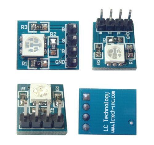
Here is a simple RGB LED testing code for Arduino IDE:
int LEDred = PD5;         // Colour  red is connected on Pin PB2
//int LEDgreen = PD3;     // Colour blue is connected on Pin PB1 (PWM)
int LEDblue = PD6;        // Colour gruen an Pin 6

int p = 3000;             // p is a pause with 3000ms (3 seconds)

int brightness1a = 200;   // Value zwibetween  0 und 255 gives the information about the Brightness of each colour
int brightness1b = 200;
int brightness1c = 200;

int dark = 0;             // Value 0 means Voltage 0V Spannung (LED off).


void setup()
{

pinMode(LEDblue, OUTPUT);
pinMode(LEDgreen OUTPUT);
pinMode(LEDred, OUTPUT);

}

void loop()

{

analogWrite(LEDred, dark);            // now the red LED will be turned off
analogWrite(LEDgreen, brightness1b); // green LED on
delay(p);


analogWrite(LEDgreen, dark);        // green LED off
analogWrite(LEDblue, brightness1c);   //  blue LED on
delay(p);


analogWrite(LEDblue, dark);         // blue LED off
analogWrite(LEDred, brightness1a);
delay(p);


}
Downloads
| HCHO sensor (ino) | download |
| RGB LED (ino) | download |
| Dust sensor (ino) | download |
| Steppermotor and RGB LED (ino) | download |
| Sensors and steppermotor plus LED simple code(ino) | download |