Testing the Robot's Capabilities
Software Used
The following software were used in this week's assignment:- Eagle was used to design the PCB.
- Arduino IDE was used to write the code and upload the code.
Testing My Board with Inputs and Outputs

But first, i wanted to make sure that my board really works before testing the inputs and outputs.
So in the beginning, I performed various test to check if my board is working, and then to check if i can successfully recieve data from my inputs and issue and save data on my outputs.
You can download the test file from the following link: Serial Test This code tests if the board works and sends data to the serial monitor
Next i tested the board using the very famous Blink code.
After that, i tested all the inputs and outputs of the board.
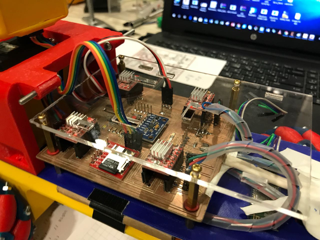
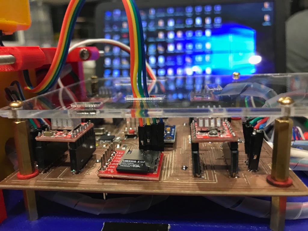
To program the board, I used an FTDI cable through the FTDI pin found on my board. As shown in the image above, the Ground pin is labeled on the board. The following process is usually followed to upload the code on the Board.
- Compile the code and check for any bugs
- Choose the baord as Arduino/Genuino Board from the "tools" drop down menue
- Choose the Port related to the board
- Upload the code to the baord using the "Upload" button
1 - Stepper Motor
In order to control a stepper motor, a Stepper Motor Driver is required which will recieve two signals from the microcontroller in addition to two power supplies, one coming from the Control Board and the other is the Voltage Needed to power the Stepper Motors.
Each stepper motor driver has the following connections
- Reset pin which is connected to the 5V power source, either from the Arduino Board, or any other board
- Sleep pin which is also connected to the 5V power source, either from the Arduino Board, or any other board
- Step pin which is connected to a digital pin which will be set as an output pin and control the direction of the rotation
- Dir pin which is connected to a digital pin that is set to be an output and control the steps of the motor
- GND pin which is connected to the GND of the power source or board you are using
- VMOT pin that is connected to the positiove poleof the motor power supply
- GND that is connected to the GND of the motor power supply
- B2, B1, A1, and A2, that are the output pins going towards the stepper motor.
In order to test all stepper motors, i used a code that drives all motors together, once the board has voltage on it. Below is the code used to test the movement of the four stepper motors
2 - Servo Motor
The Servo motor is maily used to produce a controlled angular motion. The servo motor is connected to the control board using 3 pins:
- Vcc which is connected to the 5V power supply from the board
- GND which is connected to the GND pin on the control board
- Signal pin which is the output pin that controls the motion of the servo
Below is the code used to control a servo motor
3 - microSD Transflash Breakout
The main tool i will be using to save the data collected by the robot is the microSD Transflash Breakout.
Breakout board for the microSD socket that is not much bigger than your fingernail. Compatible with the SPI interface found on any SD card, this tiny form factor was created for cell phone storage and is perfect for your next MP3 project! Board comes fully assembled and tested.
The microSD Transflash Breakout has 7 pins:
- Vcc that could be connected to a 5V or 3.3V power suply.
- GNG pin which is connected to the GND of the control board
- SCK which has to be connected to SCK pin of the micro controller, known by the Analog 5 pin on the Arduino Board
- D0 pin which has to be connected to the MISO pin of the microcontroller.
- DI pin which has to be connected to the MOSI pin of the microcontroller.
- CS pin which is connected to a digital pin.
- CD pin which is connected to a digital pin.
You can check the full details of the SparkFun microSD Transflash Breakout by visiting the following link SparkFun microSD Transflash Breakout Below is the code used to save data on the micro sd

4 - Ultrasonic Distance Sensor
As mentioned previously, the Ultrasonic Distance Sensor is a Digital Sensor. The HC-SR04 Ultrasonic Sensor Module has four pins:
- Vcc which is connected to the 5V power source, either from the Arduino Board, or any other board
- Trigger pin which is connected to a digital pin which will be set as an output pin
- ECHO pin which is connected to a digital pin that is set to be an Input
- GND which is connected to the GND of the power source or board you are using
You can download the data sheet for the Ultrasonic Ranging Module HC-SR04 from the following
Accelerometer and Gyro (MPU-9250)
The main sesnor i am using in my Pipe Surveying Robot is the the MPU-9250.
This sensor is used to cllect 9 different values from the 3-Axis Accelerometer, Gyro, & Magnetometer MEMS found on its single chip.
The module has 10 pins:
- Vcc that could be connected to a 5V or 3.3V power suply. The MPU-6050 module has a voltage regulator on board
- GNG pin which is connected to the GND of the control board
- SCL which has to be connected to SCL pin of the micro controller, known by the Analog 5 pin on the Arduino Board
- SDA pin which has to be connected to the SDA pin of the microcontroller, known by the ANalog 4 pin on the Arduino board.
- EDA pin
- ECL pin
- AD0 pin
- INT pin is connected to the GND of the control board
- NCS pin
- FSYNC pin
You can download the data sheet for the MPU-9250 9-DOF 3-Axis Accelerometer, Gyro, & Magnetometer from the following link Below is the code used to read data from the Ultrasonic Sensor
Testing the Robot Functionalities

To do that, i had to test the following main capabilites must be achieved for it to be successful:
- Motion in all directions
- Capability to detect obstacles and stop
- Capability to gather angular and position data
- The ability to regulate position according to the measured angular data
- Capability to store the data on an external microSD memory card
1 - Testing Motion
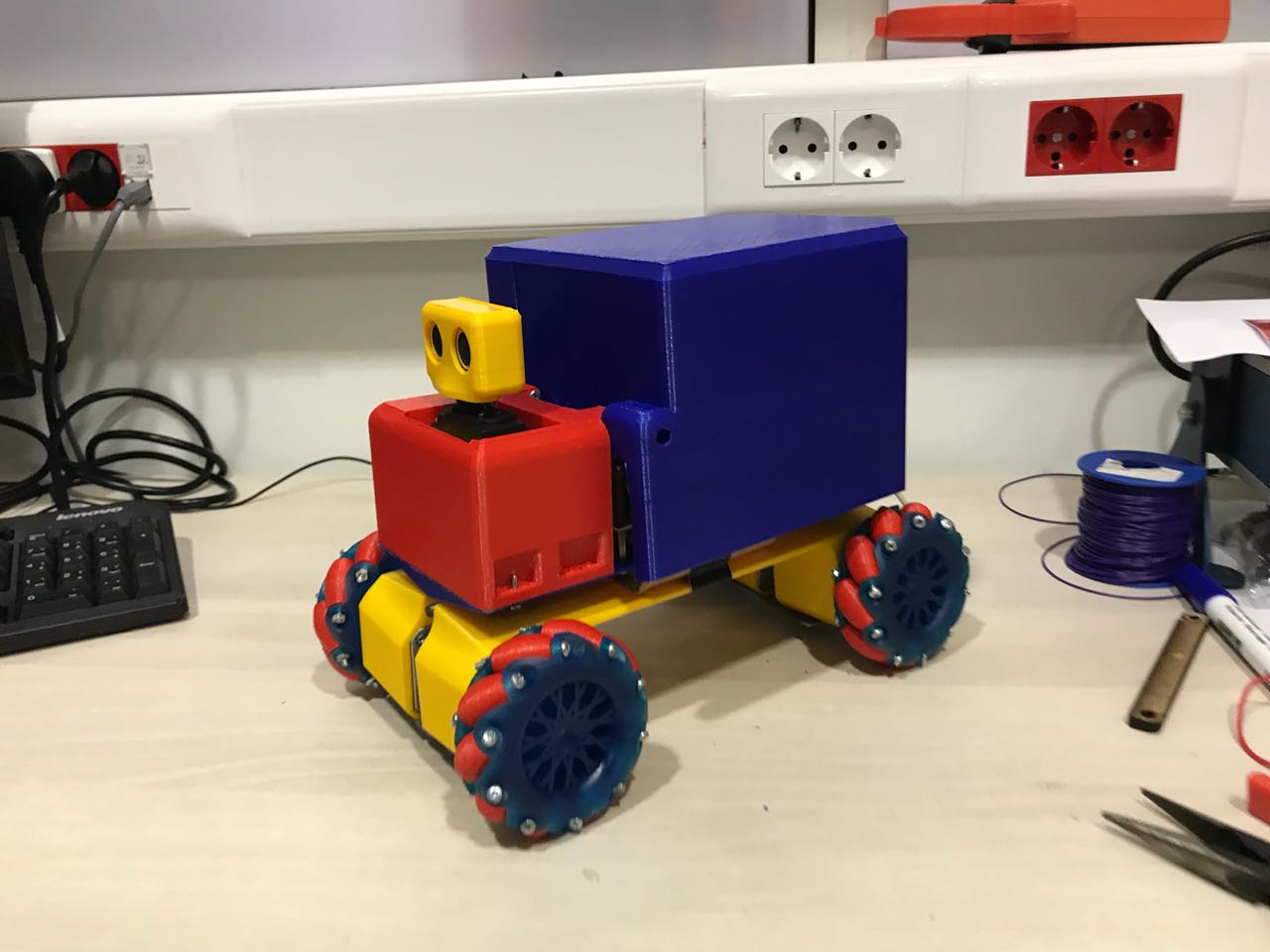
In order to test the movement of my robot, and test the functionality of the mecanum wheels, i prepared an Arduino code that would allow me to control the robot remotely through bluetooth. This code reads from the serial monitor, and accordingly, it performs the motion function previously set.
To control the robot remotely, i used the following link Arduino Car application on the Android Google PLay as it seemed perfect for the functionalities i had in my project.
In addition to that, i wanted to build my personal application that has the same functionalities of this application. So i created my remote control app using MIT app Inventor. But it could be the ugliest app you have ever seen, but it does the job. You can download the app from the following link
2 - Stopping At Obstacle
Next i wanted to test the capabilities of the ultrasonic sensor. To do that, i updated the previous code, to stop the motors when an obstacle is detected.
To test the ultrasonic sensor, i used the example code found in the Arduin IDE.Below is the code used
3 - Testing Servo - Scanning
The next step was totest the functionality of the servo motor, and see if scanning works when an ostacle is met. I used a code that set various angles of the servo, and measure the distances at the different angles, compares the values, and then returns the angle the robot should go to.
4 - Testing Full Functionalities
After finalizing all functionalities, the final step was to check if the MPU-9250 works and if the data is saved on the micro sd. To do that, i upgrated the remote control code, to measure data from the MPU- and save it on the Micro Sd, which was done successfully.
