Discovering Various 2D and 3D Modelling Software
The following tools are among the most common software used for 2D Vector Design: I have personally used all 4 software mentioned above, however, my favorite software that I used for 2D sketching is the Autocad. I use AutoCad as a digital replacement to Graph Paper. It is very user friendly, easy to use, and perfect for fast sketching with exact dimensions. A step by step guide of how to use AutoCad will be shown below.
The following tools are among the most common software used for 2D Raster Design: I have personally never used a 2D Raster Design, and probably will never do. It is mainly used for editing images by artists and graphic designers. It is not the best tool to build objects with exact dimensions.
The following tools are among the most common software used for 3D Design: I have tried most the software mentioned above for 3D Modelling. However, each software is best for something. Rhino for example is mainly used by Architects, best for designing 3D surfaces and Mathematical shapes. On the other hand, Fusion 360 and Solidworks are mainly used by Mechanical Engineers and Product Designers, best used for designing various machine parts and assembling them, to simulate various mechanisms. I like using 3D Max for building vases.
Personally, I prefer using the 123D Design software for fast 3d Designs, and Fusion 360 for more complicated 3D Designs. A step by step guide of how to use Fusion 360 and 123D Design will be shown below.
The following tools were mainly used by me to show how 2D and 3D modelling can be used:
- AutoCad was mainly used by me as a fast and precise sketch book, mainly to visualize how my Final Project is going to look like, the various options I have, and the limitations I have that affect the design.
- 123D Design was used to show a simple and straight forward way to design 3d objects fast and easy.
- Fusion 360 was mainly used to 3D model the various mechanisms and various parts that my final project will be using.
1- Using AutoCad for 2D Design
In order to visualize the various designs, my "Pipe Surveying Bot" could have, and the various limitations that affect the size and the shape of the bot, i used AutoCad. I tried to draw the various mechanisms that i could use for my design and the different dimensions of pipes my bot can survey based on the proposed design. Below is a detailed guide of how the different designs were achieved.
Note: Parametric functions cannot be used on AutoCad to control the dimensions of parts and edit them later. The only parametric functions you can use is the position of a part with respect to another (parallel, perpindicular...)
You can download the original files from the following links:
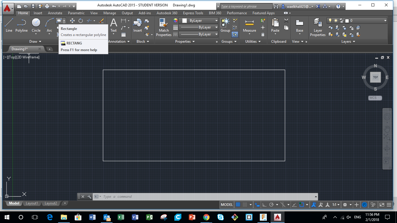
Step 1 - Drawing a Rectangle, the Main Body
To start designing, you have to start somewhere, and the most important part in any system or machine is the Main body. It's where the electronics and main components that control the system will be located. So First i had to start by drawing the Main Body.
Based on my experience in the field, water supply pipes could vary between 4" (100mm) and 30"(750mm) in diameter. However, most used pipes are between 6" (150mm) and 18" (450mm), and that was my main target. I had to think of a tiny main body for the Bot that could fit in all those pipes with different diameters.
Saying that, I chose to have the main body to be cylindrical in shape with a length of 20 cm and a diameter of 10 cm.
To represent that I started by drawing a Rectangle on AutoCad using the "Rectangle" Comand as shown in the picture.
Step 2 - Drawing the Connection for the Legs
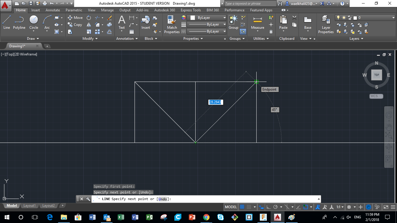
The next step was to draw the hinges where the legs will be fixed but rotating around its axis. So using the same "Ractangle" comand, two equal squares were drawn starting from the center of the Length of the Main Body. One square to the left, and the other to the right.After that, using the "Line" comand, two diagolnals were drawn for both squares to locate the center of the circles, that represent the axis of the legs.
Step 3 - Drawing Circles
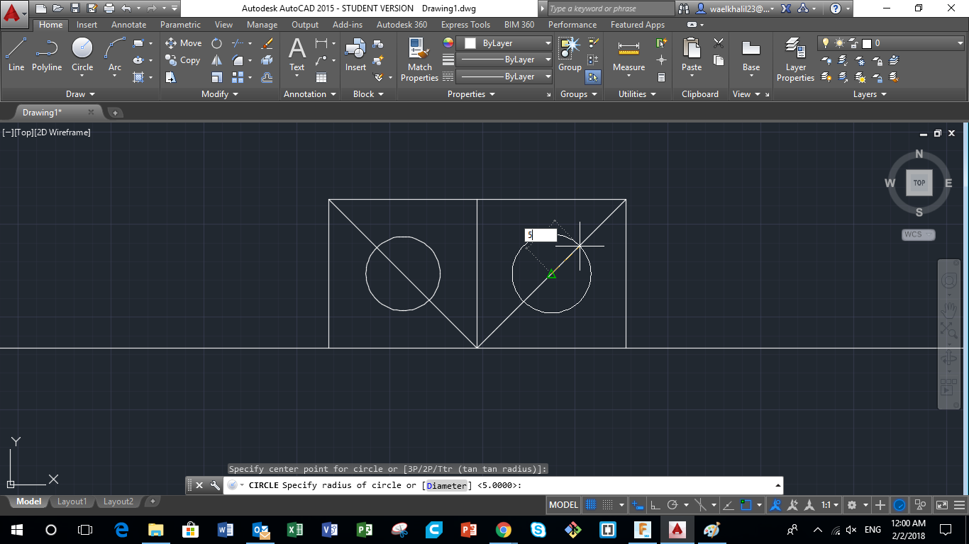
After drawing the diagonals for both squares, I drew 2 circles of Dimater 5mm which represents the axis that the legs will around. Using the "Circle" command, locate the center of the circle first, which is the midpoint of the diagonal, press enter, and then assign the diameter of the circle.
Step 4 - Fillet for Corners
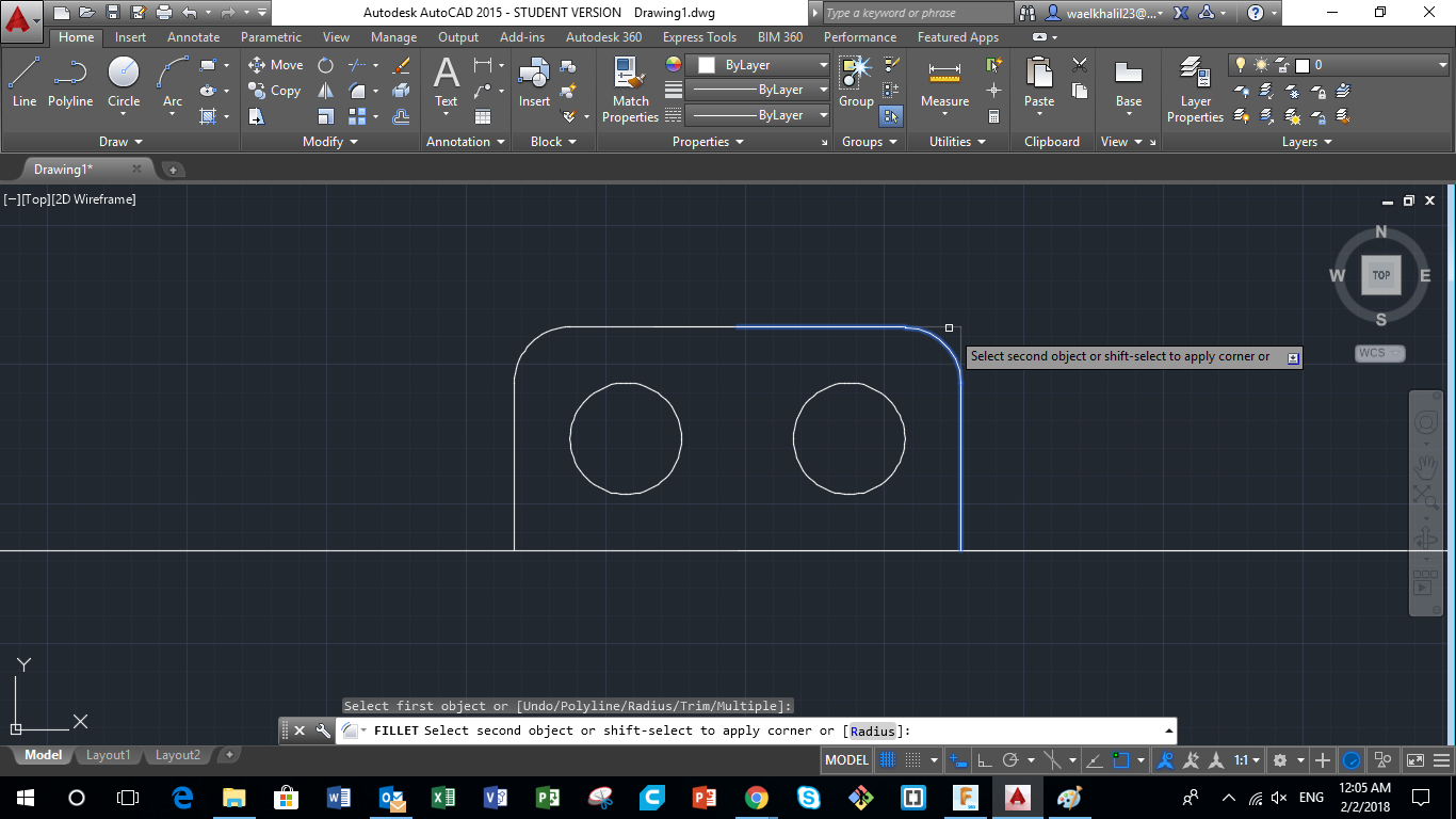
In real life, sharp edges and corners are ugly, sharp and could cause some injuries. For this reason, we need to make the edges as round as possible. To achieve that, using the "Fillet" comand, choose the two lines that form the sharp edge, and choose the intended diameter.
Step 5 - Draw the Wheels and Set in Position
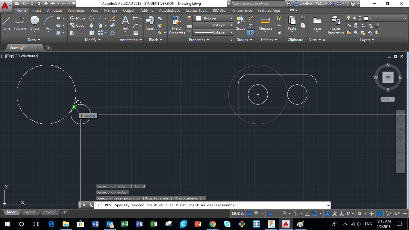
After drawing the main body, I needed to draw the wheels. I chose to have wheels having a 30mm diameter. To do that, using the "Circle" command, I drew a cirlce of diameter 30mm. I chose the center point first then entered the intended diameter. After doing that I, drew another circle around the edge of the Main Body, to reprsent clearance needed between the body and the wheel. After that, using the "Move" command, I moved the wheel to the edge of the clearance cirlce.
Step 6 - Drawing the Legs
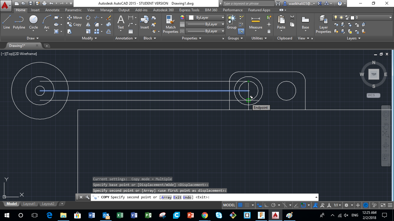
The next step is to draw the legs that will carry the main body. To do that, using the "Line" command, i drew a line between the center of the Axis and the Center of the Wheel. Following that, using the "Offset" command, I made two copies of the line at an equal distance from the first line, which will represent the edges of the leg.
Step 7 - Drawing Wheel Details
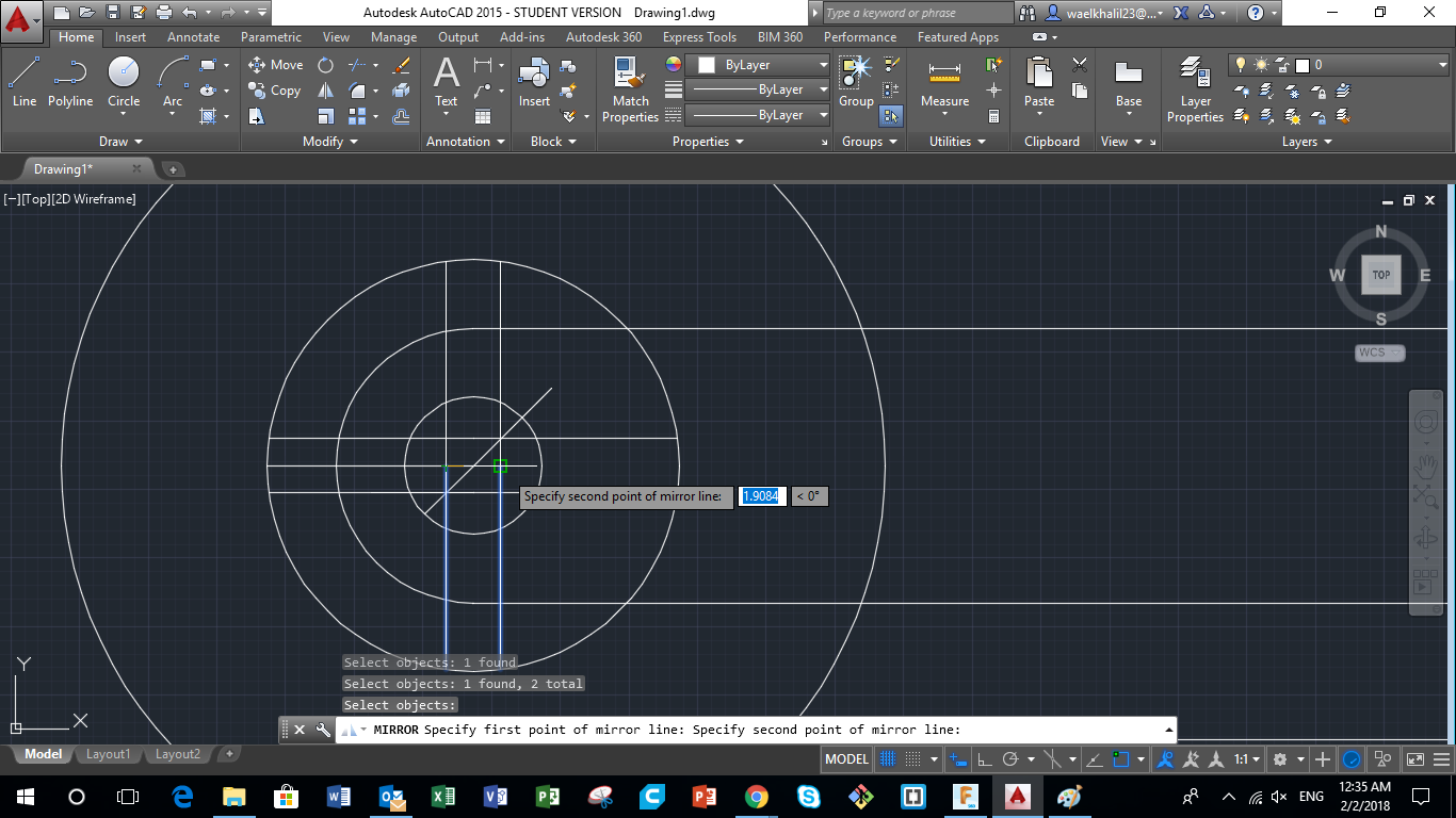
Next I wanted to draw the details of the wheel. To do that, first using the "Line" command, I drew a line from the center of the wheel going to the edge of the wheel. Next, using the "Offset" command, two parallel lines were drawn, that will represent one beam in the wheel. After that, using the "Mirror" command, i mirrored the beam into 3 different directions, thus achieving the 4 beams of the wheel.
Step 8 - Trimming Extra Lines
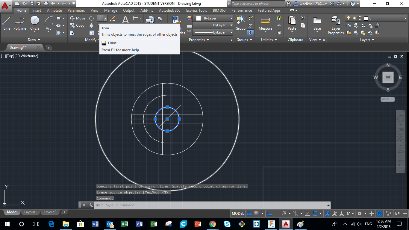
After the previous steps, many lines appear to be extra and ruining the drawing. To solve that, using the "Trim" command, I trimmed all extra lines in the drawing that are not needed.
Step 9 - Mirroring Legs
After drawing one leg, we need to draw the rest. The best thing about Autocad is that you don't have to repeat drawing similar parts. What I easily did was mirror the legs using the "Mirror" command, where the mirror axis is the center line of the Main Body.
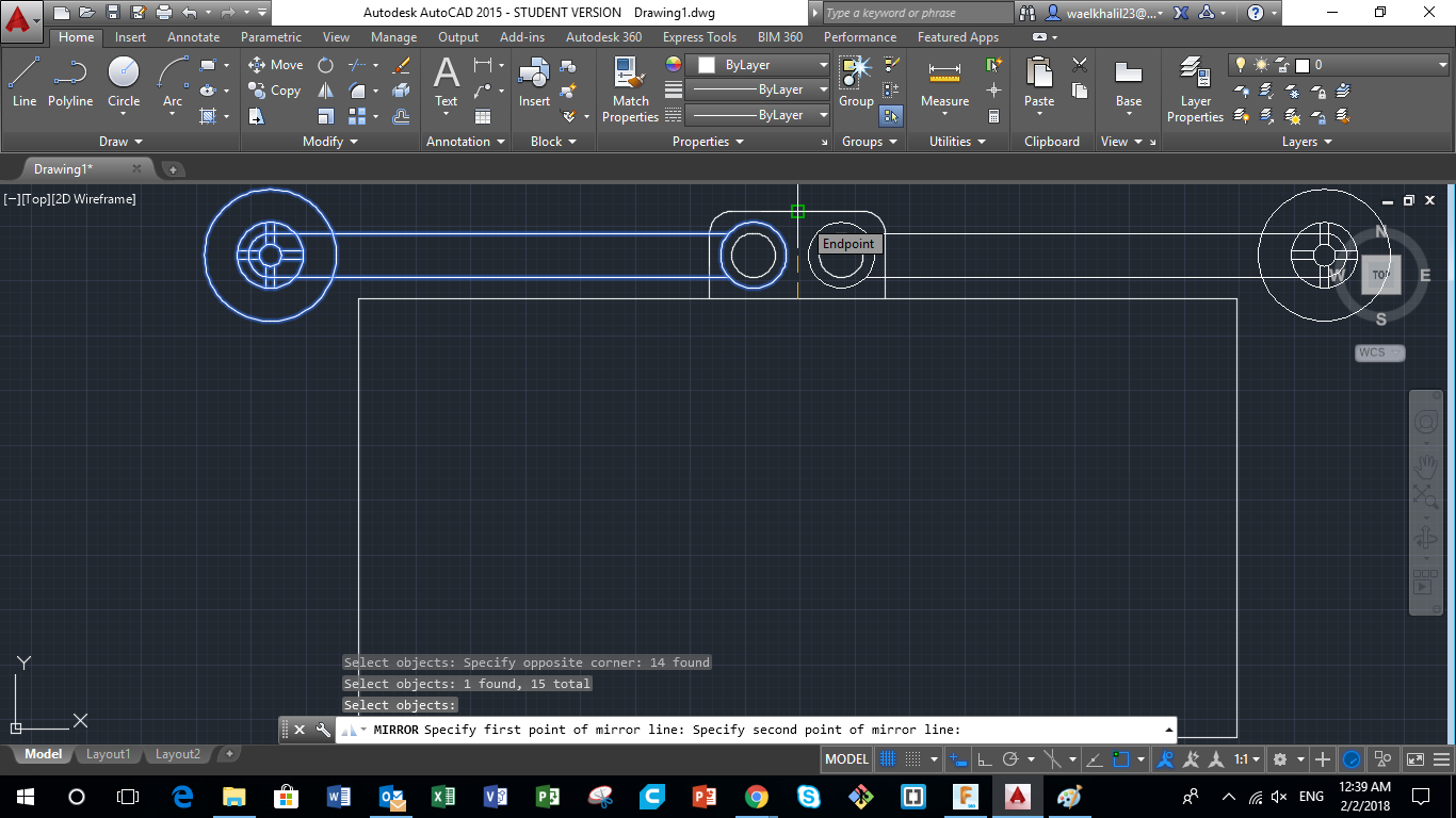
Step 10 - Drawing a leg at a Different Angle
Copy the existing Leg first and put it aside so we can use it as a reference first using the "Copy" command. Now using the "Rotate" command, select the wheel with the leg, then choose the center of the axis around which the leg rotates, and then move the leg to intended angle. After that, using the "Mirror" command, mirror this leg with respect to the center line of the Main Body.
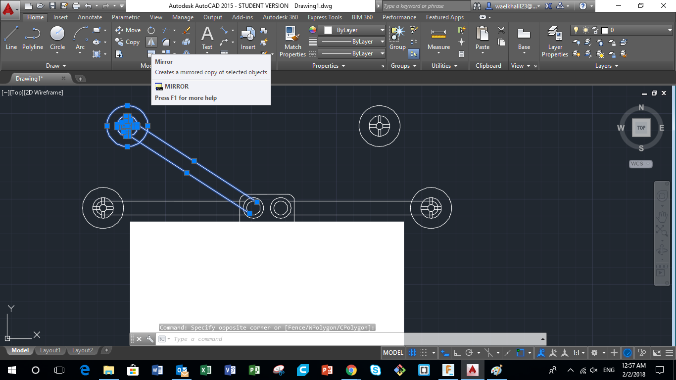
Step 11 - Mirroring Legs to the Other Side of the Main Body
After that, to get an idea of the dimentions of the pipe, the bot can survey, i had to draw legs on both sides of the main body. Please note that the drawing is not a side view of the robot, but it represents the dimensions only for visualization.
Saying that, using the "Mirror" command, I selected the legs on one side and mirrore them to the other side, along the horizontal center plane of the Main body.
Thus we have a 2D visulisation of one of the mechanisms that could be used in the Bot Design.
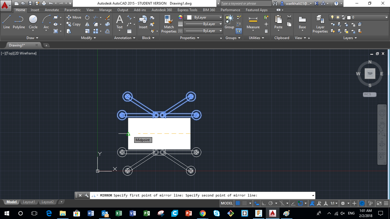
Step 12 - Find Other Mechanisms that Could be Used
Using similar commands used previously, another design was proposed to present another mechanism that could be used in the design of the Bot I am planning to build. The other design has extendable legs, piston like legs, that are located at the edge of the Main Body. When the pistong open and close, the wheels will expand to reach various pipe dimentions.
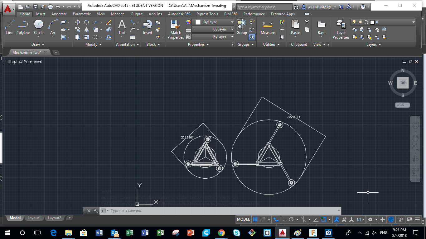
Step 13 - Visualizing Various Pipe Fitting and Limitations
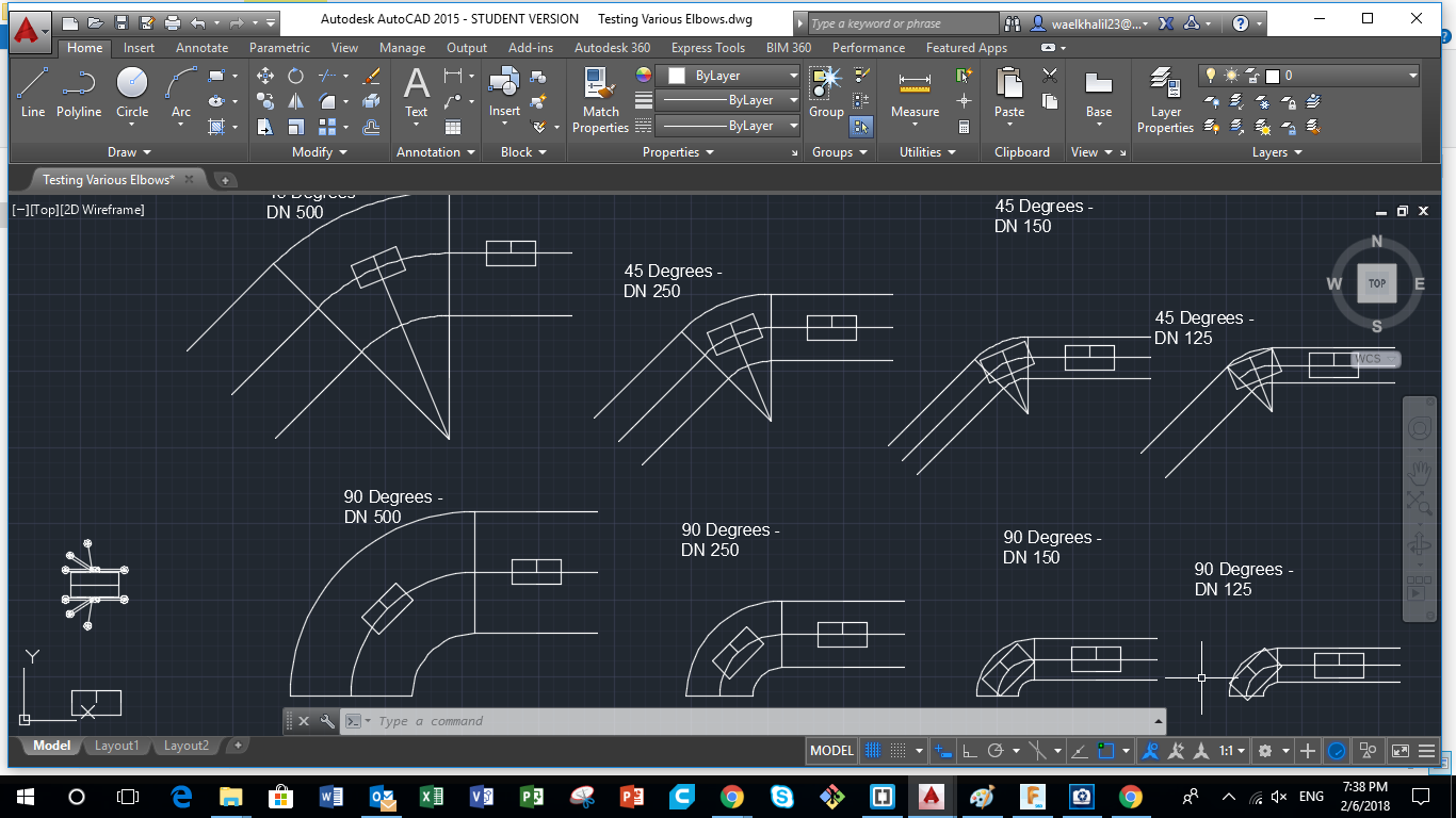
The next step was to have some drawings that would help us visualize how easy the Bot can move inside a pipe, especially at the fittings (90 degrees and 45 degrees elbows ). Saying that I drew various elbows and pipes of various diameters, and i inserted the Main Body in each one to visualize how much freedom we have.
2- Using 123D Design for 3D Modelling
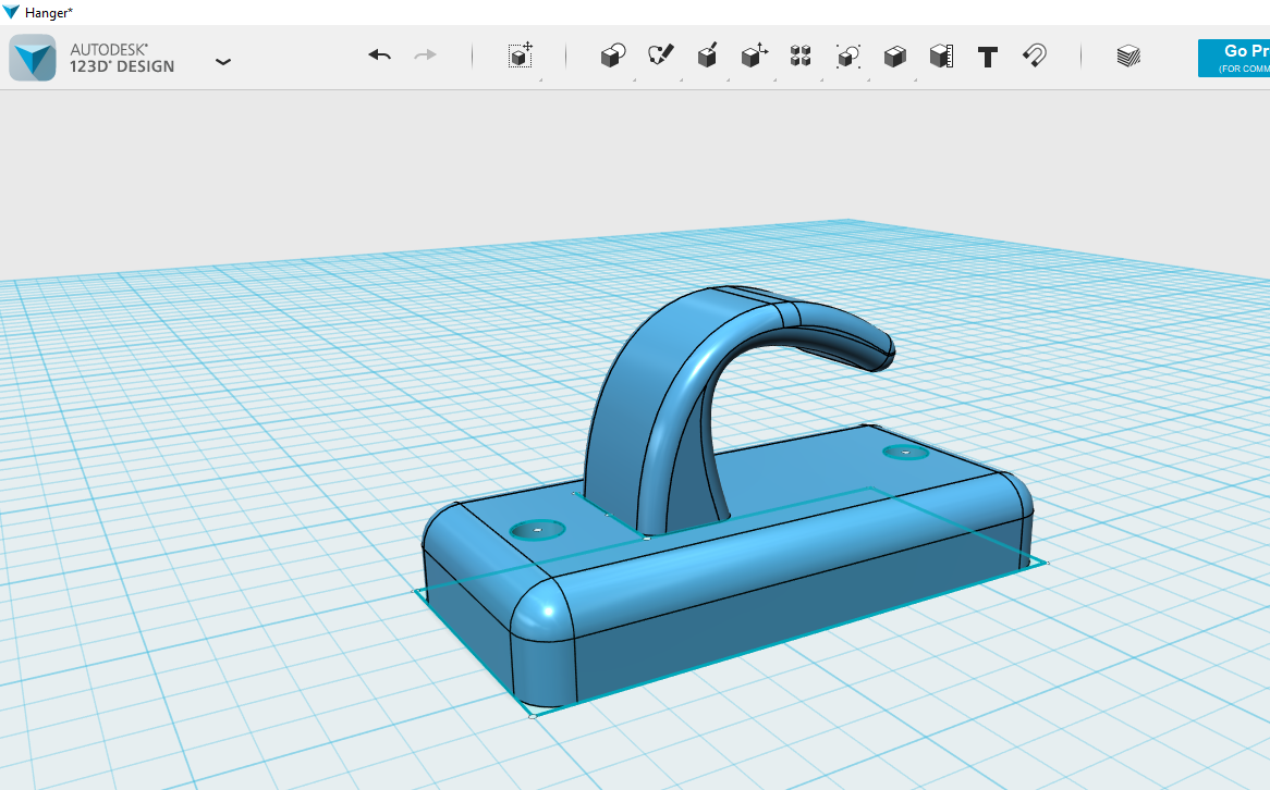
I used 123D Design to reprsent a user friendly software that could be used for fast and easy 3D modelling of various shapes. I personally use this software to designs simple things mainly for 3D Printing. However, it has limited options concerning assembly of various objects. I will show you below a step by step breif of how you can design a clothes hanger very easily.
You can download the original file from the following link Clothes Hanger.123dx
Step 1 - Drawing a Rectangle, the Main Body
First i had to start by drawing the Main Body.
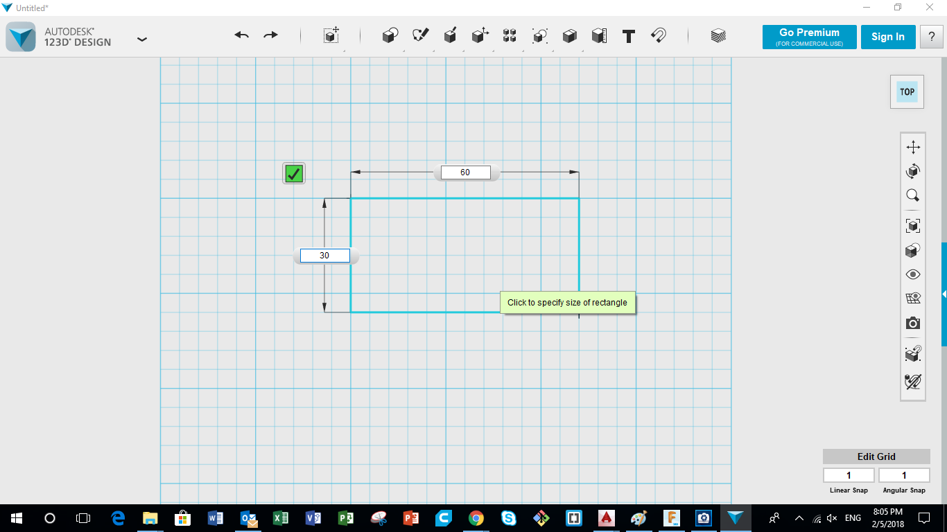
To achieve that, I started by drawing a Rectangle on top sketch using the "Rectangle" Comand as shown in the picture.
Step 2 - Extrude the Rectangle
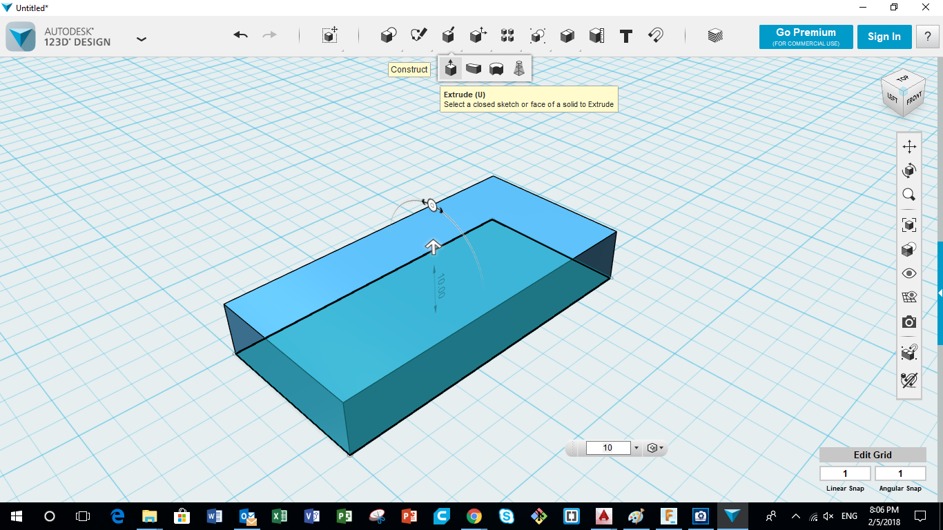
The next step is to extrude the rectangle to form a 3D body having a thichness of 10mm. Using the "Extrude" command, select the rectangle and then pull it up to the intended hight, which is 10 in our case. And voila, we have a 3d object.
Step 3 - Draw another Rectangle and Extrude
Selecting the top surface of the 3d object previously extruded, press the "Rectangle" command to draw a new rectangle on top. After that, using the "Extrude" command, pull up the new rectangle to create a new extrution and choose the dimension to be 20mm.
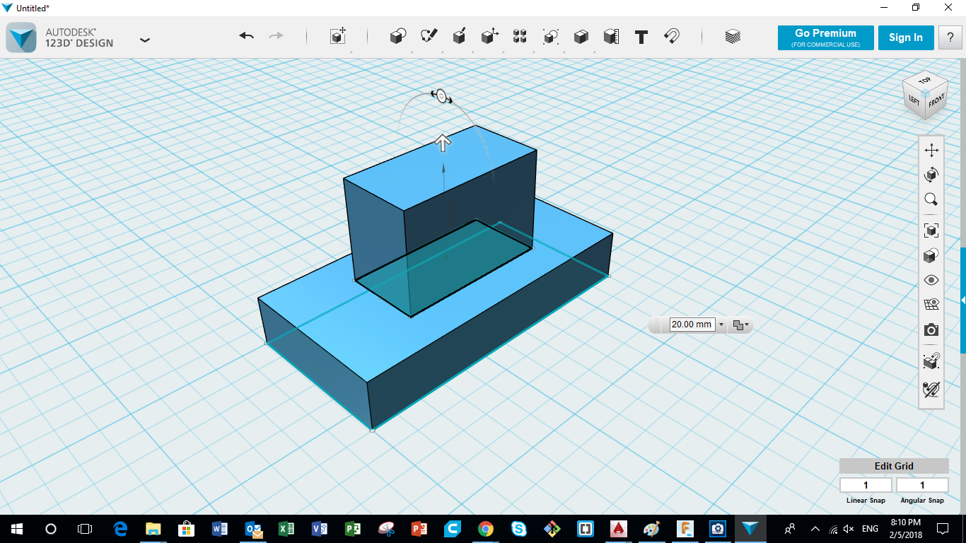
Step 4 - Shaping the Hook using Extrusion
After that, i wanted to shape the hook where the clothes will be hanged. Using the "Spline" command, i drew the wanted shape of the hook on the side of the previously extruded body. Next, I "extruded" the final curves i got from the Spline, and "subracted" them from the original body. Now we have a final shape of the Wall Hanger.
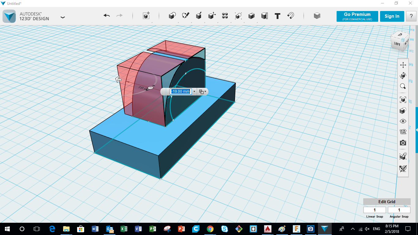
Step 5 - Drawing Screw Holes for the Cloths Hanger
After drawing the main body, I had to make two holes that will be used to fix the hanger in the wall. To achieve that, i drew two circles, equidistant from all sides, and then using the "Extrude" command, i exruded them and subtracted them from the main body. Thus we have two screw holes for our clothes hanger.
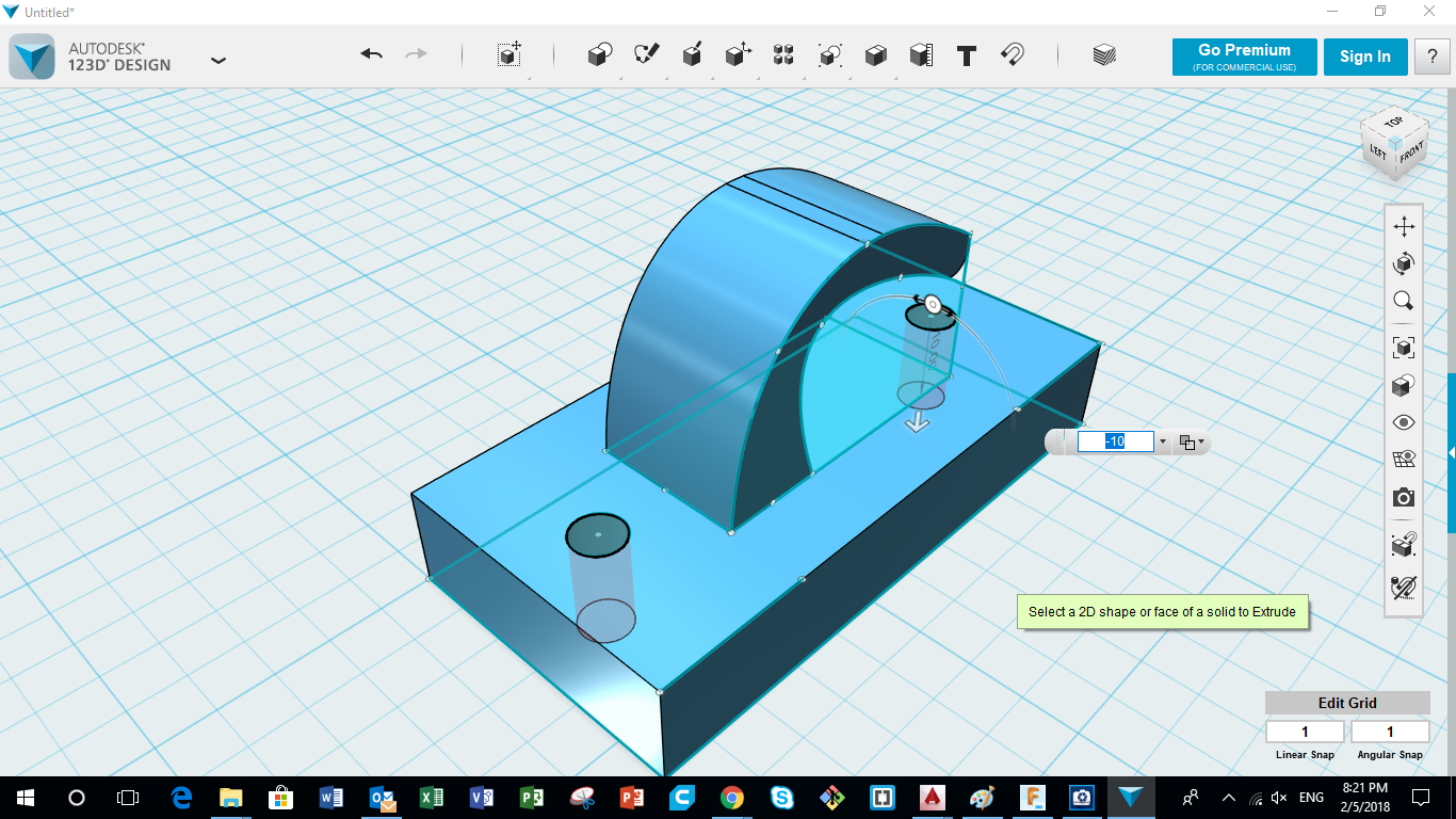
Step 6 - Filliting all Corners
The final step is to remove all sharp corners and make things look and feel better. Thus using the "Fillet" command, i selected all corners in the body, and I pushed them into the body to make round corners.
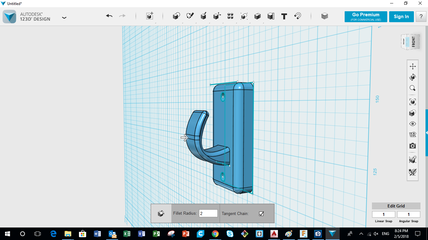
3- Using Fusion 360 for 3D Modelling the Various Bot Designs
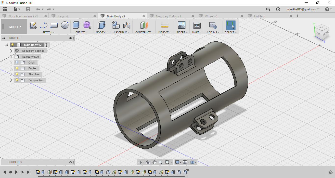
To 3d Model the Main Body, i used Fusion 360. The commands used in Fusion 360 are almost the same as the ones used in 123D Design. Saying that, i will not give a step by step guide of how to 3d model on Fusion 360. On the other hand, I will show you a video that shows how each part of the Bot is designed and the process it goes through to reach the final intended design.
You can download the original files from the following links:
Step 1 - 3D Modelling the Main Body
So the first thing to do is modelling the Main Body, which will carry all the important components of the Bot, and where all the other parts will be connected. The video attached shows how the final design shown below was reached.
The 3D Model
Attached here is the 3D Model of the Main Body. Feel free to explore my design and check out all the details.
Step 2 - 3D Modelling the Legs
After deigning the Main Body, i designed the Legs that will be connected to the Main Body, and eventually carry the Bot in the pipes. First the pattert was drawn on the Top Sketch using the "Circle", "Line", "Trim" and "Extend" Commands. After that the pattern was pulled to a thickness of 10mm using the "Extrude" Command. Next, I used the "Fillet" command to make a curvy connection between the main beam and the axis cylinder.
The 3D Model of Legs
Attached here is the 3D Model of the Legs. Feel free to explore my design and check out all the details.
Step 3 - Using Parametric Functions
In order to make things simplers and more easy for fast designs, parametric functions could be used to achieve that, by setting a constant length that will be used throughout the whole sktech. The images below Represent how parametric functions could be used.
So step one starts by setting the needed parameter and naming it.
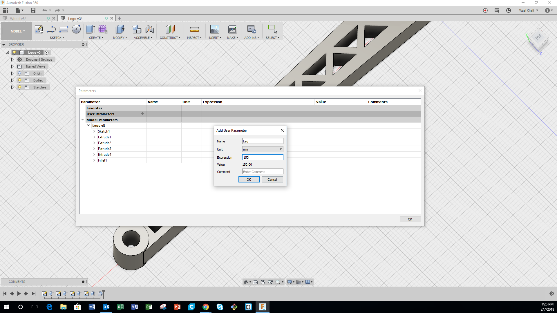
Parametric Functions Representation
The video below shows how I used permetric functions in Fusion 360 to edit the dimensions of the Legs.
Step 4 - 3D Modelling the Wheel
The next step is to design a wheel that could be used in the Pipe Surveying Bot. First, the pattern of the wheel was sketched using the "Circle", "Line", "Trim" and "Extend" Commands. Following that, the pattern was extruded to variable thicknesses. Next, a perpendicular plane was chosen, where I drew the cross-sectional pattern of the wheel. After that, using the "Revolve" command, i revolved the pattern around the axis of the wheel thus reaching the final design shown.
The 3D Model of Wheel
Attached here is the 3D Model of the Wheel. Feel free to explore my design and check out all the details.
Step 5 - 3D Modelling Another Second Mechanism
After design the first Main Body, I recognized that I have some limitations concerning the maximum diameter the bot can reach. Saying that, i tried designing another mechanism that could be used for my Pipe Surveying Robot. The idea is having piston-like legs fixed at both ends of the Bot, which will expant and contract, thus achieving various pipe diameters, with more stability. The video shows how I reached my final design.
The 3D Model of Second Mechanism
Attached here is the 3D Model of the Second Proposed Mechanism. Feel free to explore my design and check out all the details.
Step 6 - 3D Modelling Piston Legs
Now I had to design new legs that are piston-like, having adjustable dimensions. Those legs will be installed in the cylinders shown at the edge of the Main Body in the previous design shown. The video shows all the steps followed to achieve this design.
The 3D Model of Second Mechanism
The final step is to remove all sharp corners and make things look and feel better. Thus using the "Fillet" command, i selected all corners in the body, and I pushed them into the body to make round corners.
