Computer Controlled Cutting
Discovering Various Computer Controlled Cutting Mechanisms
So the objective of the third week is to discover the various equipment and technologies used for cutting digital designs into various material. There are many different Computer Controlled (CNC) machines available that are used for cutting into a wide range of material. However, we tested only two technologies in this assignment, the Laser Cutter and the Vinyl Cutter.
We had a Group Assignment and an Individual Assignment this week.
- Group Assignment
The group assginment was to characterize the laser cutter we have in the lab and make test parts that vary in the cutting settings and dimensions.
- Individual Assignment
The individual assignment was mainly two parts:
- Cutting something on the vinyl cutter
- Designing, Laser CUtting, and Documenting a parametric Press-Fit Construction Kit
Machines Used
The main two machines used in this week's assignment are the Laser Cutter and the Vinyl Cutter.
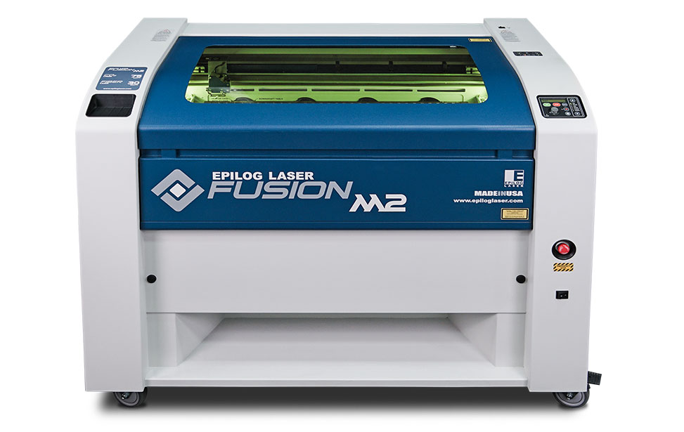
- Epilog Fusion M2 120 Watts was used for laser engraving and laser cutting in this assignment. This Epilog Fusion M2 uses the CO2 Laser Technology to cut and engrave. The laser source is guidged by 2 axis (X and Y) that guide the focal point of the laser where cutting will occur.
- GCC Puma III was used for Vinyl Cutting in this assignment. The Vinyl cutter is a CNC machine that controls a blade that cuts into different soft material, based on a digital design.
Software Used
The following software were used for 2D Vector Design in this week's assignment:
- Adobe Illustrator
was used for laser engraving the Berytech Fab Lab logo in various DPIs,to check the output of the Laser Cutter.
- CorelDraw
was used to make fast 2D designs mainly for testing the different capabilities of the Laser Cutter. It is an easy software that could be used for color mapping.
- AutoCad
was the main software used for 2D design. I used it to design the Press-Fit Kit.
1- Characterizing our Laser Cutter
In order to discover the power of the Epilog Fusion M2 Laser cutter we have in our lab, and the various capabilities we could achieve using it, we decided to make various tests. To undergo the tests, we had to prepare the test documents first and then know how to control and change the settings of the Laser Cutter.
Preparing Files and Laser Cutting
The laser cutter usually recieves a 2D vector file that could be done on any 2D Vector software.
To cut and engrave on our laser cutter, the following procedure was followed:
- Building the Design
The shapes that I want to cut or engrave were first designed on different software such as CorelDraw, Adobe Illustrator, and AutoCad.
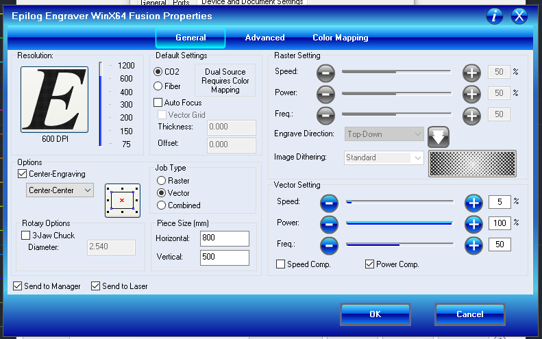
- Choosing the Laser Cutter's Settings
After the design is ready, the next step was to choose the settings we need to have the best result. There are different variables that affect the final product coming out of the Laser Cutter. Among those variables are the Power, Speed and DPI. We can also use Color Mapping to choose various settings for objects on the same Digital Design. Using color mapping allow to choose different settings for objects having different colors.
- Forwarding the Job Order
After choosing all the variables, send the order to the laser cutter.But before pressing Play on the Laser cutter, we have to manually set it up the printer with respect to the material we intend to use.
Setting Up the Laser Cutter
After preparing the file and the relative settings we need, the next step is to place the material we want in the laser cutter and set it up according to the thickness of the material.
To cut and engrave on our laser cutter, the following procedure was followed:
- Setting the Laser Focus:
Using the “V” shaped manual focus gauge, we determine the correct distance from the focus lens to the top of the material we intend to cut or engrave. Place the manual focus gauge on the carriage and place the object to be cut or engraved in the upper left corner of the machine. Use the arrow keys on the control panel to highlight the light next to the word Focus. You can now move the Joystick up or down to move the table appropriately until your material just touches the bottom of the gauge.The speed at which the table rises or lowers can be controlled by applying varying pressure upwards or downwards on the Joystick. Once the focus position has been established, remove the gauge. Press the Reset key.
- Manually Changing Focus Anywhere on the Table:
If you wish to focus at a point on the table other than in the upper left corner, you can do so by activating the Jog feature of the machine. Press the Arrow keys on the Control Panel until the light next to Jog is illuminated. This now activates the Joystick to allow you to move the lens carriage of the laser to the desired position on the table. Again, varying the pressure applied to the Joystick will vary the speed at which the lens carriage moves to the desired position on the table. Once the lens carriage is located over the desired portion of the table, use the procedure above for raising and lowering the table until the focus gauge touches the top of the material. After you have focused, press the Reset key to send the carriage back to its Park position.
- Performing the Cut
After setting up the Focus and Location of the Laser with respect to the material, we can now easily go forward with cutting or engraving our file. This step is very simple, Close the lid of the laser. Click the Go key on the keypad to start the job. The laser will then start the job.

Engraving using Various Settings in Different Material
So the idea was to understand the different settings of the Laser Cutter that could affect the output products.
There are three main variables in the laser cutter setting that could be changed and respectively affect the output of the machine. Also the same settings could have different results between various material or various thichknesses of the same material.
The settings are:
- Power is the variable that controls the power of the laser emitted by the machine.
- Speed is the variable that controls the speed of the laser passing over the material we are cutting or engraving.
- DPI is the variable that controls the pixels of the engraved image or shape. Higher DPI means higher number of pixels. Low DPI causes a highly pixelated engraving.
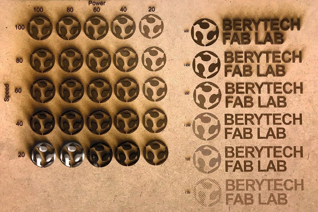
Saying that, we prepared a Test File on CorelDraw, that has the Fab Lab Logo with various colors and many 2 x 2 cm squares (hairline thichness) . Different settings were assigned to the different colors used, variating both the Power and Speed of the Laser.
Both the Power and the Speed was variated from 20 to 100. A table was done that represents the various settings used.
After that, a test was done with various DPIs to check the various results we could reach by changing the DPI.
Cutting Test
As shown above, for each material we tried various settings for Raster, Vector and DPI. The lowest speed setting was 20 and we didn’t get clean cuts. So we decided to do another test for cutting using a variety of speeds under 20 to find the exact setting that makes a clean cut through which would not only give us the parameters for the kerf test but also shows how deep each setting would cut.
Below is a list of all materials tested and the optimal setting for a clean cut:
- MDF 3mm: P=100 F=50 S= 1-20, All speed settings cut through with different kerfs.
- MDF 5mm: P=100 F=50 S= 1-12, Only a Speed of 12 and below made clean cuts.
- Acrylic 3mm: P=100 F=50 S= 1-20 All speed settings cut through with different Kerfs
- Acrylic 5mm: P=100 F=50 S= 10-20 Only a Speed of 10 and below made clean cuts
* Note: Anything below the minimum cut speed has a higher kerf. *
Kerf Test
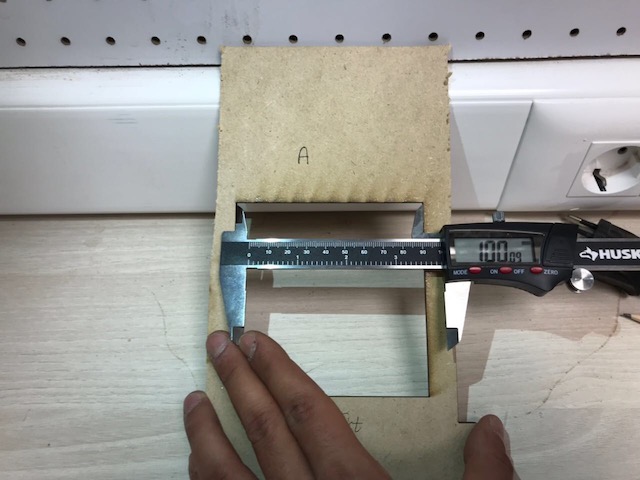
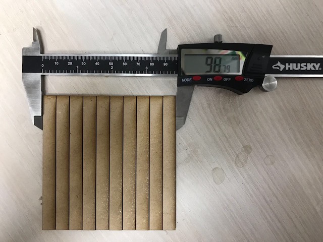
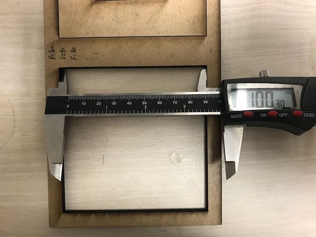
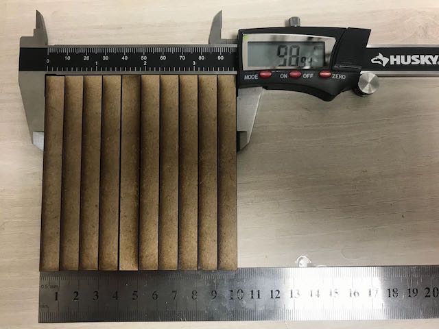
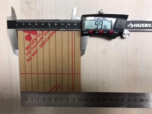
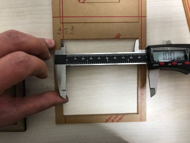
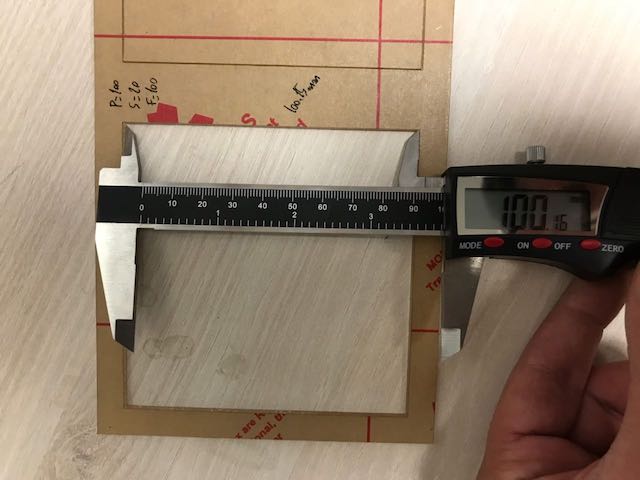
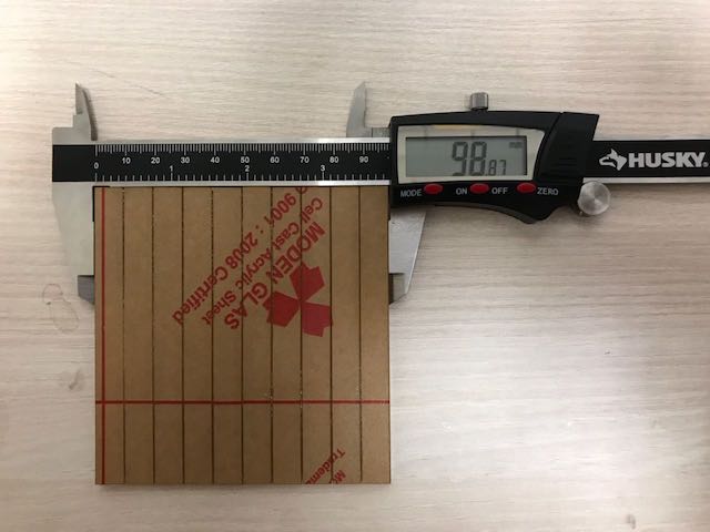
For the kerf test, we used the data collected above to have the lowest kerf. So the minimum speed with a clean cut, we used the same template for all materials which consists of a square with 11 cuts inside, to calculate the kerf we used the formula of deducting the width of the stacked cut bars (A) from the interior width of the square they were taken from (B). And since we had 11 cuts the equation would be:
Kerf= (A-B) / 11
The kerf calculation and result for each material below:
- MDF 3mm: P=100 S=20 F=10 Kerf= 100.28 - 98.79 / 11= 0.126
- MDF 5mm: P=100 S=10 F=10 Kerf= 100.18 - 98.91 / 11= 0.11
- Acrylic 3mm: P=100 S=20 F=100 Kerf= 100.15 - 99.37 / 11= 0.07
- Acrylic 5mm: P=100 S=9 F=100 Kerf= 100.12 - 98.87 / 11= 0.113
Fitting Test
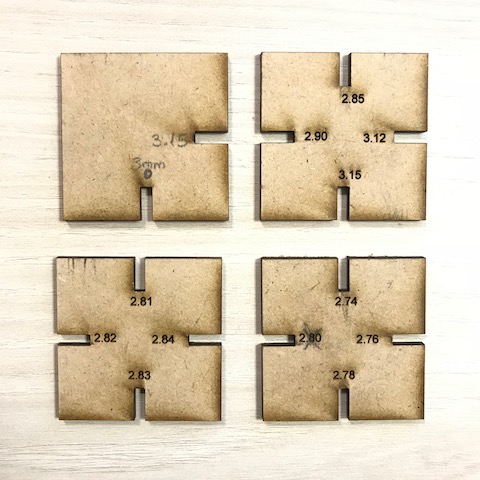
Since we all agreed to use MDF 3mm, additional tests were done using the kerf test results as a benchmark. Using the minimum cut setting and kerf test gave us a kerf of 0.126 mm. Even though this test was accurate it was not fitting as anticipated which leads us to the second test.
We made square shapes with a variety of cut dimensions on each side. Using the data provided from the kerf test, and since we were using 3mm MDF, we started the cuts at a width of 3.12mm which proved to be loose (obviously since we needed to deduct the kerf from the 3mm instead of adding it). We then did the different cuts below until we found the “sweet spot” right between loose and to tight. Our optimal Kerf for a perfect fit and hold was 0.24 mm which means the cut width we had to make was 2.76 mm and it turned out to be perfect.
Downloads
Kerf Test