Building the FabTinyISP
 Summary:
The FabTinyStar is yet another version of an AVR ISP programmer/board that can be produced in a fab lab using a milled PCB and readily available components. The project is based on the efforts of many people. For more history of the FabTinyStar and the people who have contributed to it, please refer to Zaerc's FabTinyStar page.
Steps:
- Introduction
- PCB Fabrication
- Assembling the PCB
- Check Your Work
- Software Installation
- Get and Build the Firmware
- Program the ATtiny45
- Test the USB Functionality
- Blow the Reset Fuse
- Test Your Programmer
Introduction
This version (the "FabTinyISP Minimal" is a minor revision to Zaerc's version 0.3 (Bas), with small modifications:
The reset switch and target power switch have been removed. The reset switch adds cost and isn't incredibly useful on an ISP programmer, as the target can be easily reset through a software command. The target power swtich has been removed as providing power to the target through the programming port is usually discouraged. Users who understand the implications of this are welcome to build one of the FTS designs with the switch.
The copper ground pour has been removed and replaced with individual ground traces; this allows novice solderers to mill away more of the copper. All components solder to clearly defined pads on both sides.
The extra pads connecting to the USB data lines were removed; this version is targeted solely at being an ISP programmer rather than being a general-purpose tiny45 board.
The PTC thermistor was removed; as this part currently isn't in the inventory most users would build it with a 0Ω resistor anyway. As the option to provide target power has been removed, it should be much more difficult to create a condition where the polyfuse would be needed.
The Makefile has been replaced. Targets for programming the fuses on an ATtiny45 have been added. The original Makefile also results in problems on case-insensitive filesystems (i.e. Windows).
This page describes how to build, program, test, and debug the board.
Notes
One possible point of confusion in this document is that the device you're building will become an AVR programmer, but you also need a working AVR programmer in the process of building it. Your board refers to the new programmer that you are building. Programmer refers to the working programmer that you'll use to initialize yours. At the end of this document, your board becomes a programmer.
PCB Fabrication
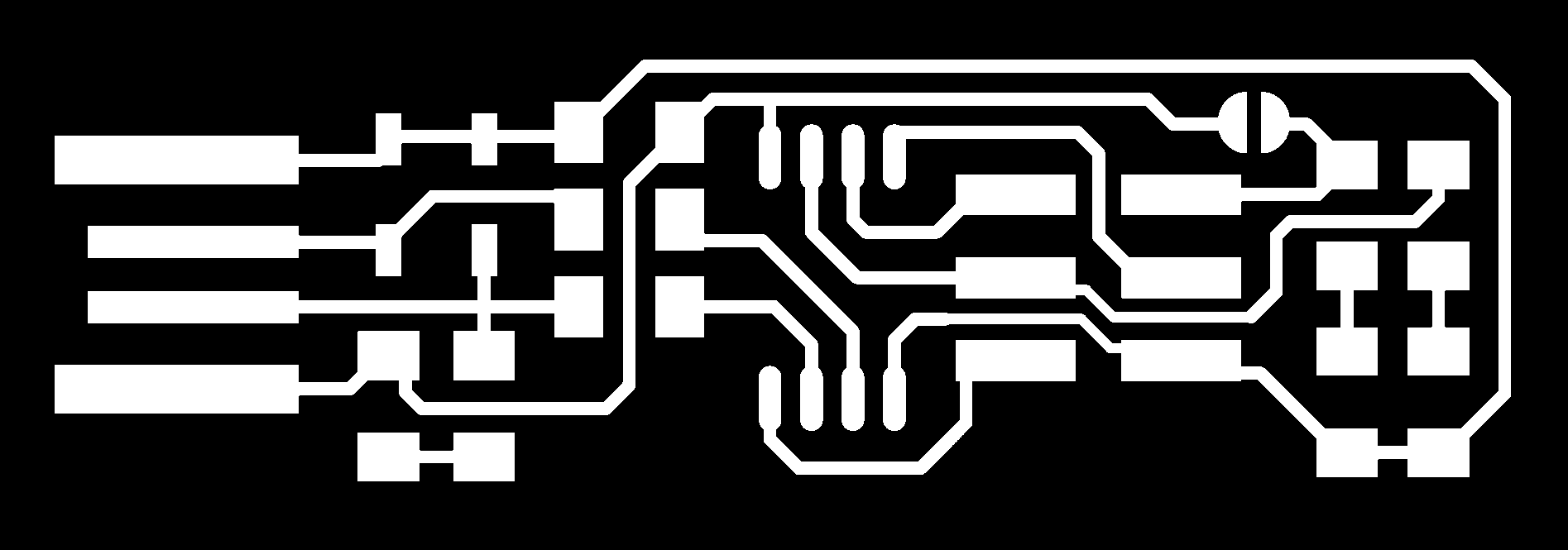
Download the PNG files for the traces and the board outline:
Traces (1000 dpi)
Outline Cutout (1000 dpi)
The Altium source files are available here if you want to modify the design.
Since there are different processes for milling on different machines, this is not described here. Please refer to a PCB milling reference that's applicable to the equipment in your shop.
The finished PCB should look something like this:
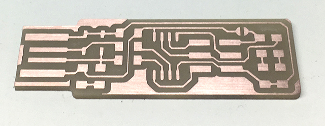
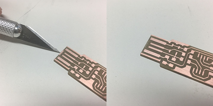
Depending on the number of offsets you milled, there might be a tiny bit of copper left at the edge of the board in front of the USB contacts. 5 offsets should be sufficient to remove all of the copper in the milling process, but takes a bit longer to mill. If you milled fewer offsets (I did 3 in the above photo), the extra copper can be removed with a knife. Only the copper in front of the pads needs to be removed; the copper left on the sides is fine.
Assembling the PCB
Obtain the components:
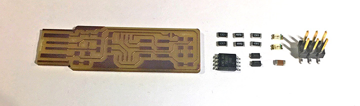
- 1x ATtiny45 or ATtiny85
- 2x 1kΩ resistors
- 2x 499Ω resistors
- 2x 49Ω resistors
- 2x 3.3v zener diodes
- 1x red LED
- 1x green LED
- 1x 100nF capacitor
- 1x 2x3 pin header
The LEDs and their associated resistors are optional; the red LED lights when the target circuit is powered, and the green LED lights when the programmer is talking to the target.
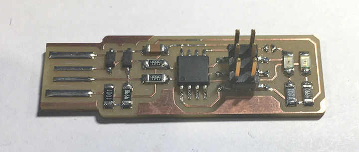
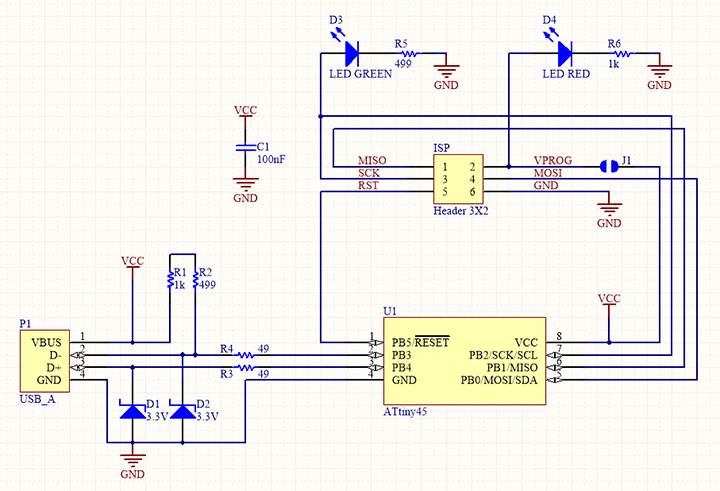
Solder the parts to the PCB, using the schematic and board image below as a reference for component values and placement. Start with the most difficult parts (the ATtiny45) first, so you have the most access. Install the ISP header last, as it is large and can get in your way if you do it earlier.
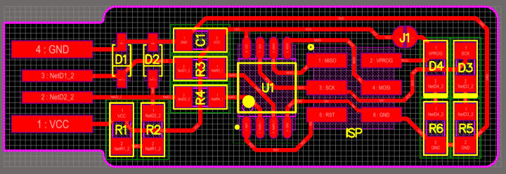
Note the components that must be installed in the correct orientation:
- The zener diodes are marked, both in the drawing and on the packages, with a line on the cathode side.
- The LED cathodes on the PCB drawing are marked with dots and thicker lines. Package marking conventions differ between LED manufacturers, but there is usually a green or black line visible on the cathode side of the epoxy lens. Some LEDs have an extra copper marker on their cathode pad on the bottom. Some print a small arrow on the bottom, which corresponds to the schematic symbol: the arrow points towards the cathode. If in doubt, you can use a multimeter in the diode check mode; the LED will glow slightly when the red probe is on the anode and the black probe is on the cathode (this is also useful for determining color).
- The ATtiny45 marks pin 1 with a dot laser-etched into the corner of the package. Pin 1 is marked in the drawing with a dot as well.
Use solder to create a bridge on the jumper near the ISP header (J1). This temporarily connects VCC to the Vprog pin on the ISP header so that the header can be used to program the tiny45. (The programmee supplies voltage on this pin and the programmer detects it). Once it's programmed, we'll remove this bridge to turn the board into the programmer rather than the programmee.
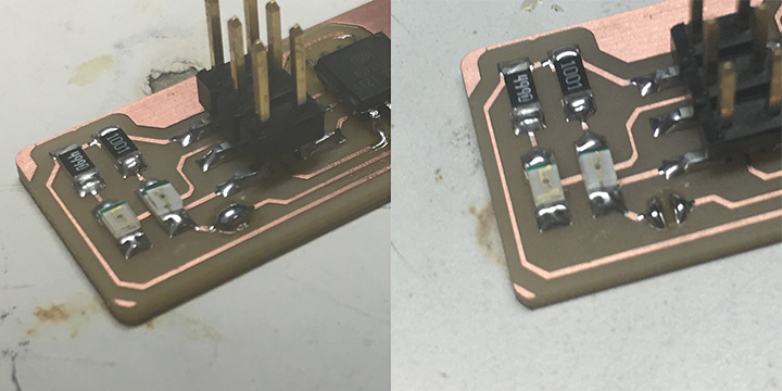
The solder jumper, bridged and not.
Improve the USB Connector
The PCB ends up just slightly thin to work well in most ports. To ensure a good USB connection, I recommend the following one or two improvements.
First, flow some solder onto the USB contacts on the board to build them up a little bit. Heat the pad and apply solder, moving the iron tip along the pad to distribute it. Once you have enough solder, wipe the iron tip across the pad in one continuous motion to even it out into a smooth layer. If you don't get a smooth layer, you need more flux: clean off your iron tip on the sponge, apply a little more solder to the pad, and wipe across it again. Excess solder will come away on the iron tip. (See the above image of the finished programmer for how the USB pads should look).
Doing the above is sufficient most of the time, but I still like to add a little more thickness by gluing some extra material to the bottom of the PCB. A small scrap of plastic clamshell packaging works well. I use a tiny drop of CA glue to affix a small piece to the bottom of the USB connector area, then trim the excess plastic once it's set. (Do be careful not to get superglue on the rest of the board, especially the USB contacts on the other side).
Check Your Work
While it may seem early to start debugging already (we haven't even tried anything yet!) it is always prudent to check your work before plugging in a board. It only takes a couple of minutes and can save you headaches down the road.
- Check your board against the schematic and PCB layout image to make sure that you have installed the correct components in the correct locations and orientations.
- Inspect your board visually. Components should be flat on the board, not tilted with pins in the air. Solder connections should be smooth, and solder should have flowed both onto the pin and onto the pad. If you still see a lot of exposed copper on the pad, or the solder is lumpy and draws up into a point where you removed the iron, you probably don't have a good connection. Reflow by applying heat and flux (either from a flux pen or by adding a tiny bit more solder). Also look for unwanted solder bridges between nearby traces and pins.
- Use a multimeter to check for shorts between
VCCandGND.
Software Installation
Before you can build and program the firmware onto your board, you need to set up your development environment. You'll use this setup for all of your AVR programming for the class. The setup differs a bit for each platform, but once the software is installed it should work more or less the same on each platform.
You'll be using a command line shell (bash) in your platform's terminal to execute all of the commands below. If you are unfamiliar with using the command line, you may want to review a tutorial.
Linux (highly recommended)
For Ubuntu and other Debian-based distributions, enter the following command, followed by your password when prompted:
sudo apt-get install avrdude gcc-avr avr-libc make
MacOS
Download and install CrossPack.
Windows
Installing the toolchain on Windows is slightly more complicated. Separate instructions are provided here.
Get and Build the Firmware
Download the firmware source code and extract the zip file (on Linux, unzip firmware_45.zip). Open your terminal program and cd into the source code directory.
Run make. This will build the hex file that will get programmed onto the ATtiny45. When the command completes, you should now have a file called fts_firmware.hex. If the command doesn't complete successfully, something is wrong with your toolchain installation. Consult the error messages for information that will help you debug it.
Program the ATtiny45
First, update the Makefile for the type of programmer you're going to use to program your board. The Makefile, by default, assumes that you're going to use a programmer in the usbtiny family (e.g. another FabISP board). If you're using a different programmer, first figure out what avrdude (the programming software) calls it. Here are some commonly found AVR programmers:
Small translucent blue programmer: avrisp2
Large translucent blue programmer: jtag2isp
White box with blue stripe: atmelice
Any fabbed board with an ATtiny on it: usbtiny
Edit the file called Makefile. It is important to use a text editor intended for programmers; programs like Notepad or WordPad can add formatting information that breaks the file. On Linux, gedit (GUI) or nano (command line) are good options; Windows users might want to use Notepad++. TextEdit on OS X usually works, just make sure you save as plain text and not RTF (and make sure no ".txt" gets added to the filename). Sublime Text is another popular choice on several platforms. In general whatever you use to edit your HTML code is probably an okay choice.
Near the top of the file, find the line that says:
PROGRAMMER ?= usbtiny
and change usbtiny to whatever programmer you're using.
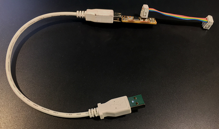
Go ahead and plug the board into a USB port. Use a USB 2.0 port, rather than a USB 3.0 port, if you have one. It is also recommended to use a short USB extension cable or a USB 2.0 hub rather than plugging directly into the port, especially if your USB ports are upside down. This will remove the strain from and reduce the risk of damage to your built-in USB ports. For example:
If you installed the red LED, it should be lit up now. If not, check the solder jumper and make sure that it is bridged. If your computer complains about a USB device drawing too much power, unplug the board and check for shorts.
Connect the programmer to the ISP header on your board. Note that there are two different orientations in which you can connect the cable; it is imporatant that you get pin 1 in the right place. Pin 1 is marked in the board diagram with a dot and has the MISO signal connected to it. If you look at the plastic connector on the programmer cable, there should be a small arrow, dot, or manufacturer's name marking the corner with pin 1. Note that there's no enforced standard for which direction the cable comes out of the connector, so look for the pin 1 marker.
Run make flash. This will erase the target chip, and program its flash memory with the contents of the .hex file you built before. You should see several progress bars while avrdude erases, programs, and verifies the chip.
If something went wrong, check:
- that the programmer is connected correctly and pin 1 on the connector matches up to pin 1 on the board
- that your board is well-seated in the USB port
- that the ATtiny45 is installed in the correct orientation
- that your soldering looks okay on the ATtiny45 and ISP header (note that shorts can happen where the traces run underneath the connector)
If you've checked all of the above and still can't program your board, use a multimeter to verify that there is continuity between the pins on the chip and the ISP header, and that there isn't continuity where there shouldn't be (shorts between adjacent pins or traces).
Once you've succesfully programmed the flash memory, it's time to set the configuration fuses. We'll do this in stages:
- First, we'll set the fuses that control where the microcontroller gets its clock source from. (The USB requires the clock to come from the PLL, and not be divided by 8). This will allow us to check that the board works as a USB device, but it won't yet be able to program other boards.
- Only after confirming that USB works, we'll set the fuse that disables the reset pin and turns it into a regular GPIO pin. This will let the chip use the reset pin to program other boards, but will disable the ability for this chip to be programmed again. Because this is not easily reversible, we want to make sure that everything else works first!
- Run the make fuses command. This will set up all of the fuses except the one that disables the reset pin. Again, you should see several progress bars from avrdude. If this step fails but the previous one worked, you likely have an intermittent connection somewhere.
Test the USB Functionality
Now we'll check to make sure that the USB on your board works, before blowing the fuse that will enable it as a programmer. Unplug your board from the USB port and disconnect the programmer, then plug it back in to the USB. Make sure the programmer you used to program your board is also disconnected from the computer.
Linux
Type lsusb in the terminal, which will list USB devices. If you see a "Multiple Vendors USBtiny" device, it worked! If it didn't, the dmesg command might provide more info on what went wrong. You want to see a message about a "New low-speed USB device" without any further errors. (Note that sudo dmesg -c will clear the messages after printing them out, which is useful to do before plugging in your board so you'll be able to tell exactly which messages are a result of plugging it in). If you don't see the "new low-speed device" message, check the pull-up on the USB line (the 1kΩ and 499Ω resistors, R1 and R2, in series between VCC and D-) for correct values and good connections (the computer uses these resistors and their values to detect what type of USB device has been connected). If you do see the "new low-speed device" message, but there are other errors after, try the following:
- Sometimes it's just a bad connection with the port; try unplugging and replugging. Check to make sure that the USB contacts are clean, and have even amounts of solder on all of them, and that the surfaces are smooth.
- USB 2.0 ports are more likely to work than USB 3.0 ports. If you don't have any USB 2.0 ports, try plugging in through a USB 2.0 hub.
- Check the traces and components between the USB data pins and the microcontroller. Make sure the zener diodes are in the correct orientation, that the series termination resistors (R3 and R4) are the correct values (49Ω) and that the connections are good. Measure continuity between the resistors and the USB contacts, and the resistors and the microcontroller pins that they connect to (pins 2 and 3). Check for shorts between microcontroller pins 2 and 3, and to other nearby traces.
Try plugging into a computer that you know has worked with someone else's board, or try plugging someone else's known working board into your computer. This will help you narrow down whether you have an incompatibility with your USB ports or a problem with your board.
MacOS
Open Apple System Profiler (Apple Menu → About this Mac → More Information; or from the Utilities folder). Select USB from the list on the left, and you should see the USBTiny listed as a device on the right. If it shows up, it is working properly. Otherwise, follow the debugging instructions above (note that MacOS does not have a
dmesgcommand, though similar information might be available somewhere in the Console app). Either check everything above, or plug into a Linux machine to see whether or not you get the "new low-speed device" message indmesg.Windows
Windows lists USB devices in Device Manager (Start → Control Panel → System → Device Manager), though it doesn't always tell you what they are until the correct drivers are installed. USB devices may also appear in "Devices and Printers" or "Hardware and Sound". If you don't know your Windows machine well enough to find whether or not the USBtiny device is showing up, you might want to plug into someone's Linux machine or Mac to check for sure whether it's working.
Blow the Reset Fuse
Congratulations, you're almost to a working programmer. The ATtiny45 on the board has the code loaded onto it and is working correctly if you've made it this far. There are two final steps left to turn your board into a programmer that can program other boards.
First, we need to change the bit that will turn the ATtiny45's reset pin into a GPIO pin. Once again, this will disable our ability to reprogram this ATtiny45 in the future, which is why we wanted to make sure everything was working before doing this. Connect your ISP programmer to your board one more time, and run make rstdisbl. This does the same thing as the make fuses command, but this time it's going to include that reset disable bit as well. You should see some progress bars, and with that, avrdude will never be able to talk to this chip again through the ISP header.
Second, we need to disconnect VCC from the Vprog pin on the ISP header by removing the bridge on the solder jumper. Sometimes the excess solder will stick to a clean soldering iron tip; if not, use desoldering braid to remove the solder from the jumper, thus breaking the connection.
Test Your Programmer
You should now have your very own working ISP programmer! But, before you call it a day, use your board to try programming another board.
Original tutorial by:
Updated by:
Craig Hobern | Fab Lab Wgtn | v1.0 | 2017-02-17 | Converted to Markdown
