
Week 17: Aplications and Implications
This week assignment was to propose the final project.
Intelligent Sunroof Project
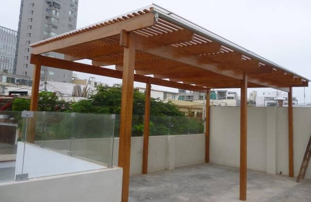
"Sol y Sombra" (literally: sun and shade) are a quite popular type of decorative outdoor structure, usually used in gardens and beach houses; I even have one at home. They are simple wooden structures.
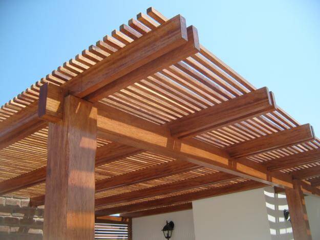
Although their popularity, I found some inconveniences, mainly that they do not provide real protection against intense sunlight and/or rain. Some add transparent plastic plates on top of the structure, giving a layer of protection, but defeating (partially) the purpose of having "sun" plus "shade".
My idea deals with creating a more versatile version of these structures, by making a small prototype (around 1x1 meters). The basic structure would be fixed longitudinal beams, with rails to hold the transverse beams. A mechanical device would be used to move the transverse beams, plus add a rotational motion to "open" and "close" the structure..
What will it do?
The intelligent Sunroof Project will be an outdoor structure intended to have both functional and decorative purposes. As for the functional part, it will provide an adjustable source of shade during daytime, useful for houses’ outdoor spaces (like terraces), plus a source of artificial lighting at nighttime. Everything keeping a stylish and customizable design.
Who’s done what beforehand?
The basic design is quite mainstrain, with several examples. In most cases they are just a cross wooden beam designs. To these, some acrylic plates (or similar) are attached to provide additional protection against sunlight and rain, plus some simple lights are hanged.
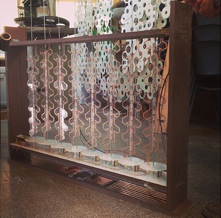
2014 FabAcademy alumni Oded Shorer and Gali Lea-Baly created the Smart Curtain which uses more or less the same principles as my project, but applied to a smaller scale and using a vertical position to make a curtain.
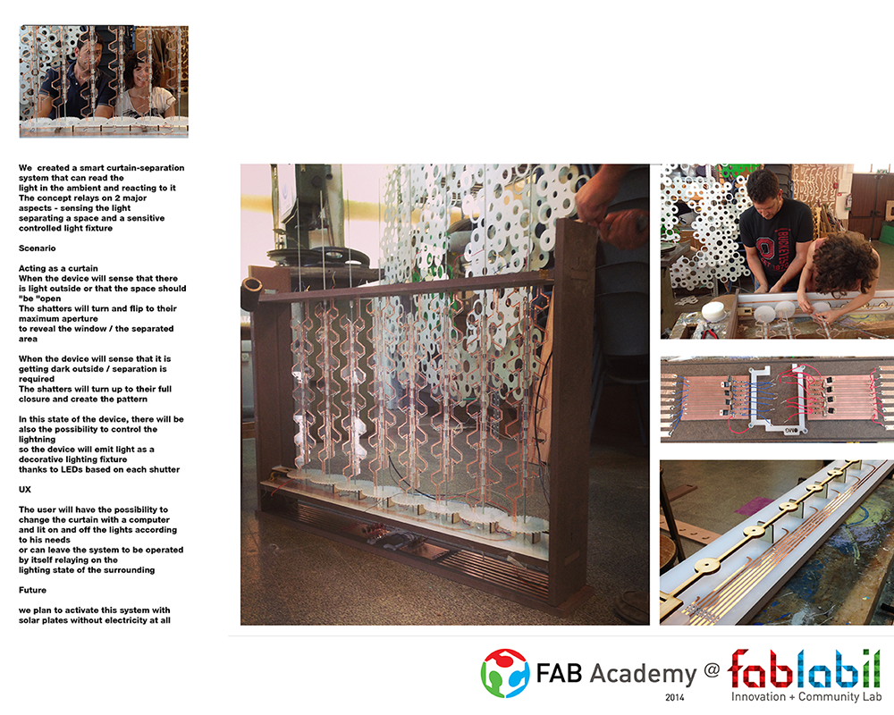
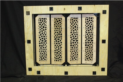
Same year alumni Hashem Joucka´s Window Shutters Construction Kit also had a similar idea.
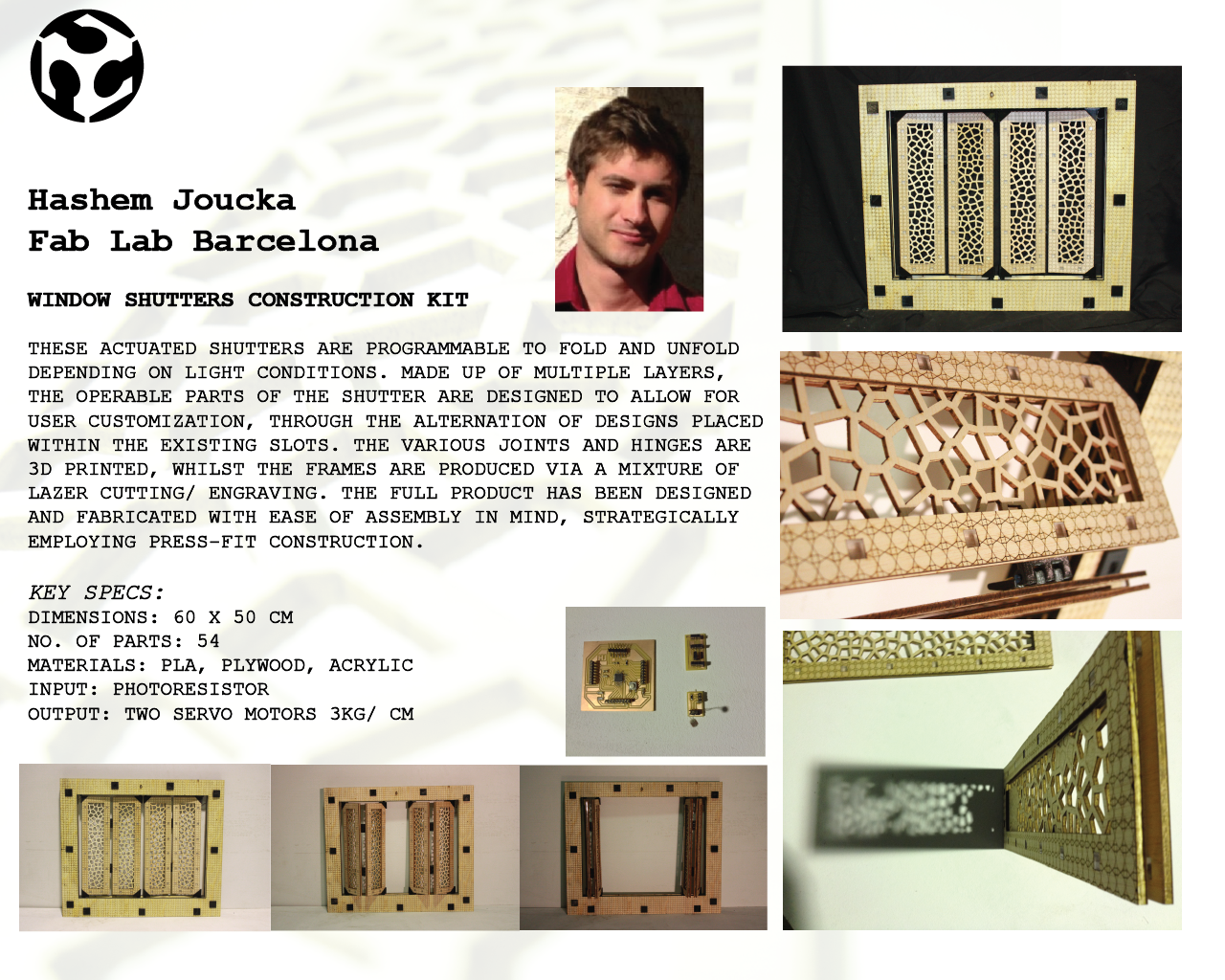
What materials and components will be required?
The following components are intended for a small version. The same components can ust be replicated and/or adjusted for full scale applications.
- 3x Honeycomb Design Cross Beams. These are the beams what will adjust to allow more or less light through. The full design is a honeycomb pattern, so two complementary types of beams will be used for this (more or less designed on Week 2). These will be made up of stacked layers of cut MDF (Shopbot) and transparent acrylic (Epilog Laser Mini). Inside will have wired LED lights too.
- 2x Longitudinal Beams: These are the two structural beams that will hold everything together, and are supposed to be anchored to the wall. They will be made up of think MDF (Shopbot) and inside will hold various mechanical components needed for the motion intended.
- 3x Mechanical Module #1: The first type of mechanical module will provide the rotational motion of each cross beam, using a still-to-be-designed set of gears. Each beam will be attached to one of these modules, and then set over railings inside one of the longitudinal beams. Possibly, all modules would be powered by one motor, by using a rack gear or endless screw mechanism.
- 3x Mechanical Module #2: The second type of mechanical module that will provide the longitudinal motion of each cross beam, using a still-to-be-designed set of gears. Each beam will be attached to one of these modules, and then set over railings inside one of the longitudinal beams. These are one of the most difficult components to design, as each one should have the same input but different output. Possibly, all modules would be powered by one motor, by using a rack gear or endless screw mechanism.
- 2x (or maybe more) railings: Railings to support the cross beams and allow smooth longitudinal motion.
- Control Panel: A central control panel for setting either automatic operation or manual o1x verride adjustments. Made of 3mm MDF (Epilog Laser Mini), 3D printed buttons (MakerBot), and electrical components.
- Electronic parts: Several electrical parts will be needed, including, but not limiting to: light-sensor module (milled and soldered Week X), temperature-sensor module (milled and soldered Week X), motor control module (milled and soldered Week X), central processing unit (Raspberry Pi 2 or Fabduino), 12V motors, 5V & 12V sources, LED strips, general wiring, etc. An option would be a Bluetooth module for manual override using a cellphone app.
- General hardware: Screws, washers, bearings, nuts, etc. as needed.
Where will they come from?
Most of the materials needed for the project are intended to be sourced from the FabLab´s inventory. Actually, most components should be designed to use the available materials. What is most likely to be needed apart from our inventory are all the small hardware parts that can be easily bought at local hardware shops.
How much will it cost?
I have not made a final cost estimate. Although, as most materials are part of the inventory, I think that I could easily be covered by the $100 budget. Additional parts should not cost more than $20. These keeping in mind that the product would be a small version (using full scale parts) to test out the functionality. Also, it should be considered that for the project many mechanical parts will be made of MDF (maybe reinforced as composites if needed) or plastic, while on a full commercial application metal parts would be needed (too expensive to make single prototype at this stage).
UPDATE: In the end, I used about $150 from the inventory, as I used much more MDF than intended. Additional pars, including electric components, wiring, nuts, bolts and washers topped up to about $10. Plus, I recycled old electrical piping, so I got that for free.
What parts and systems will be made?
Most components will be made and assembled using the lab´s materials, machines and tools. Actually, it is intended to use as few as possible bought parts.
What processes will be used?
For the project, the following processes will be required (though more could be needed on the go):
- Computer Aided Design: To design all the parts needed, mainly using Autodesk Inventor.
- Computer Controlled Cutting: To laser cut small and medium MDF and acrylic parts.
- Computer Controlled Machining: To cut big MDF parts.
- Electronic Design and Production: To make the electronic parts.
- 3D printing: To print unique pieces needed for the projected.
- Programming: To program everything needed, from the boards to the interfaces.
- Composites: If parts need to be reinforced.
What tasks need to be completed?
- Complete de sourcing of materials and parts, the main concern are the parts that need to be bought.
- Complete de design of mechanical parts.
- Complete the design and production of electronic parts.
- Program.
- Cut, make, assembly, etc. the different parts and components.
- Assemble the whole project.
- Test and adjust.
What questions need to be answered?
At this points, my main concerns are:
- How to achieve all the motions needed (longitudinal and rotational) using as few motors as possible?
- Will the 12V motors have enough torque?
- Will the structure be too heavy?
- Will there be too much friction between the parts?
- How to design the full electronic setup?
- How to program all the inputs and outputs to work together?
What is the schedule?
More or less, the schedule to finish the project is the following:
- Current week: Solve the pending mechanical designs that is the mechanical modules needed for the motion of the beams. Start cutting and machining parts. Sourcing is not really considered as most are lab´s materials.
- Next week: Make and start programming. Start assembling with made parts.
- Final week: Finish programming. Test and make adjustments.
How will it be evaluated?
I am not really sure how to fully answer this at this stage. But I can point out some indicators that would tell that the project runs as originally intended:
- Mechanism (like the gears) run quite smoothly, it is not expected to run perfectly as not the ideal materials will be used for the mechanical parts.
- “Automatic mode” should run as expected, if the programming is correct.
- When the beams are closing, they should touch themselves but not hit with one another.
- While in “closed” mode, there should be minimal to no leaks.