
Week 2: Computer Aided Design
 THIS WEEK´S FILES
This week assignment consisted on trying different CAD tools and model as much as posible of our final project using the tools that best fits out needs.
Some tools I tried
- Autodesk AutoCAD: I had some previous experience with this one as I learn the basics some years ago as part of a course of my undergrad program. It is quite a powerful tool, though I don't like much how it works around; for example if I want to change the measures of something I already did, it is not that easy.
- Autodesk Inventor: I also had some basic experience with this one. I really like GUI and how it works around, specially that the side pane contains a "history" of every step done into the model of something, and you can go back and adjust things as needed. I just went into making single objects, then assembling them, and finally making short clips about them (although the anitaion possibilities are rather limited, at least using the basics); I'm looking into making more complex videos, maybe exporting the files to another software. Very powerful software, a lot of different tools that can help aside from just modeling something. Some problems are that modelling complex geometries is quite difficult.
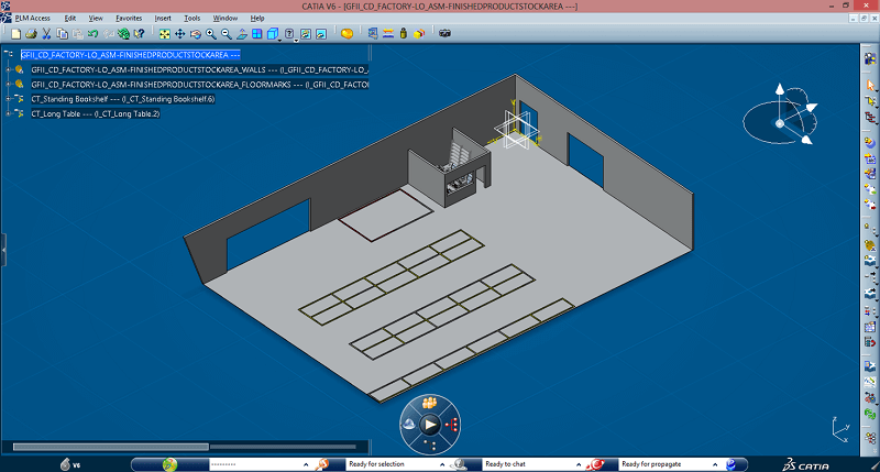
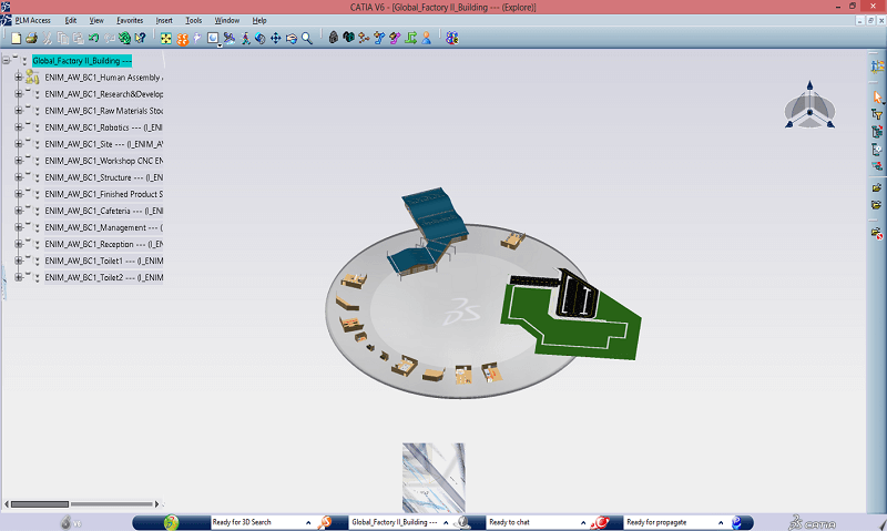
- Dassault Systemes CATIA V6: We had this one because the university used it for an international research project a couple of years ago. I has mostly the same functionality as Inventor, but I don't like the GUI as much, as I find it more difficult to ger around. Something that is both good and bad is that it works mostly on the cloud, which is positive for handling group projects and such, but a pain if the internet connection is not that good (specially considering that while modelling you can get huge files). For the mentioned projected, which consisted on designing a car engine factory, and I was in charge of designing the finished product warehouse, considering dimensiones, workflow, product handling especifications, etc.
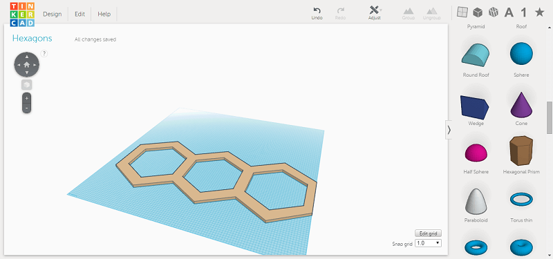
- Tinkercad: An online CAD software, really good to make quick modelling on the go. The GUI is simple and straighforward, so it is easy to learn. It doesn't have as much functionalities as Inventor or CATIA, considering its portability. I think it is more useful for quick and simple modelling, when you don't need much precision.
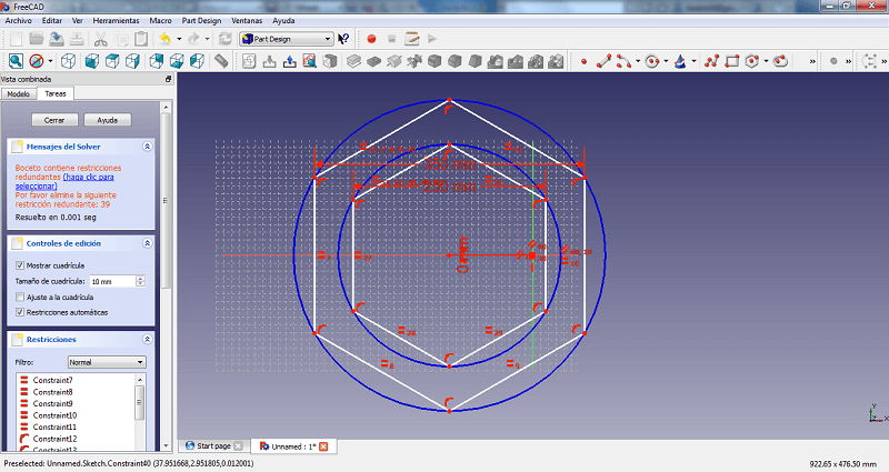
- FreeCAD: Looks and works somewhat like Inventor (though it doesn´t have as many tools), but with no pricetag (and low disk usage). Quite good one, I would use it more if I didn't have access to Inventor, specially for some quick designing.
- Antimony: The most different one from the rest. Just to start off, I runs on Linux, so I had to get a live linux usb (I tried it on Elementary OS using Linux Live USB Creator). Considering I didn't know much about Linux, I took some time just to get it to work. I played around with the default functions. The potential is very high, specially for creating some complex figures, but you need to work on making the scripts.
I have yet to try most of them in-depth, I just tried out the main functions for now.
Start modelling my final project...
Tools
- Pen and paper: Modelling on just vague ideas is not that easy, so sketching with trusty pen and paper is still useful in this era.
- Autodesk Inventor (Pro 2012): I chose to just use mainly Inventor considering that I have a more experience with it, so I can work around it quite quickly. Also, my project (at least until now) doesn't require the modelling of complex structures.
Process
First I start thinking my idea again. And I end up changing the whole design, but keeping the same functionalities for the final product. The main reasons behind this change were both mechanic and aesthetics.
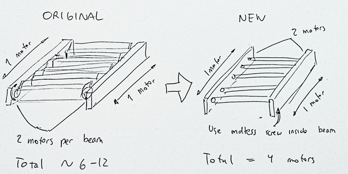
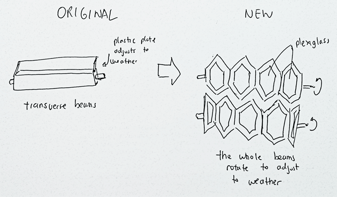
On the one hand, my prior idea require a motor (or two) to deal with the whole horizontal movement, plus one (or two) motors per transverse beam (each being a single module) to operate the plastic plates that would adjust according to the weather. In the end, I would have to stockpile motors to acomplish a simple motion, adding weight to the whole structure (not good) and a burden on the project's budget. The new design uses 2 motors for the horizontal movement (2 to keep torque balanced on the structure and not cause unnecessary stress on the components) and a couple more to deal with the weather adjustment motion (again 2 to keep torque balanced out). I still need to device the specific mechanics.
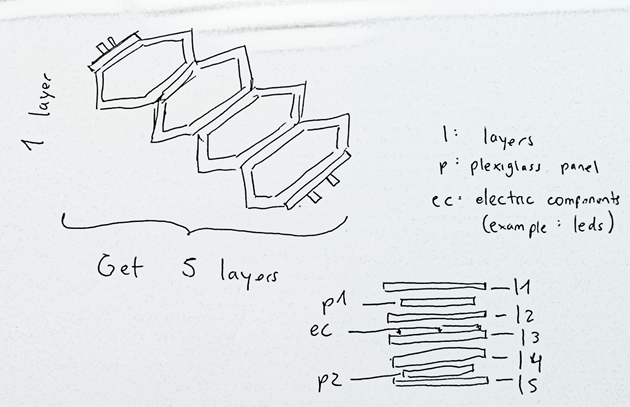
On the other hand, considering I'm making the project from scratch, why not change the whole aesthetics? I changed the basic cross beam structure (which everyone has) to a "modern looking" honeybomb design. Still, main materials would be wood and acrylic plates (or similar plastic). I also threw in there some LEDs for illumination and decorative purposes.
Then I start sketching some basic characteristics prior to CAD modelling. For the time being, I only though about the general design of the transverse beams, as I don't know yet how the mechanics would work in the fixed longitudinal beams. Each one would be composed of 5 layers of CNC cut wood, plus the CNC cut acrylic plates, adding to more or less 5 cm, but I still don't know how to get the layers together (maybe press-fit, glue, or both?).
Having a more detailed idea of my project, I proceeded to model the different pieces using Inventor. Each piece is created in individual files (.ipt)
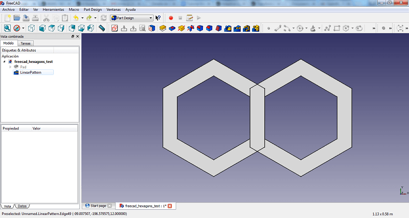
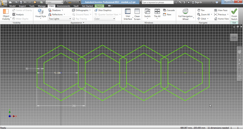
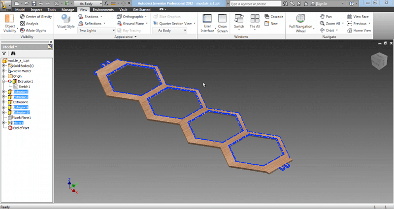
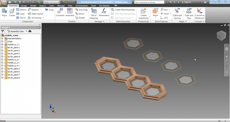
First of all, every piece starts up like an sketch. For my first piece, I drew 4 hexagons to make the honeycomb design.
After making the sketch, it is extruded to make a solid object, with a defined thickness.
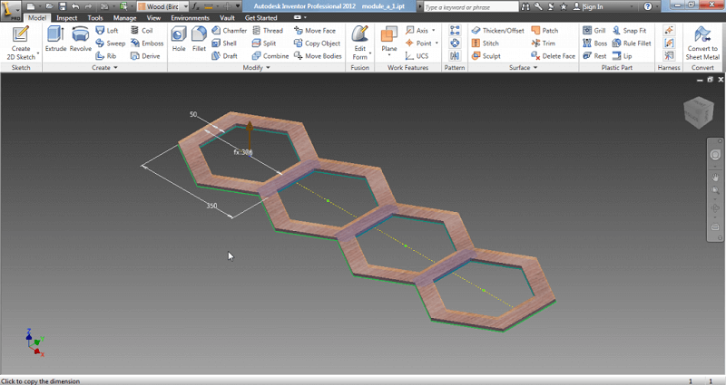
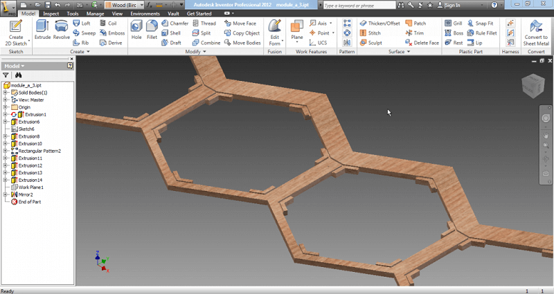
Reapeating the steps of making sketchs and then extruding them, I added more features to my object.
I repeated the same steps to make a total of 5 pieces, which make up the 5 different layers that I mentioned in my paper sketches.
Some pieces requiered a bit more detailing. For example, for layer 3 that will hold the electric components for the lighting, I added spaces to put the led strips plus some small canals to put the cables and conceal them.
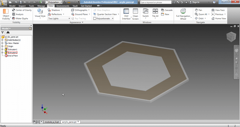
The same process is used to make the acrylic panels.
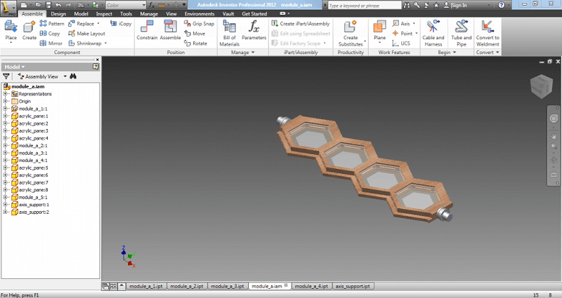
After having all my pieces ready, the next step is to assemble them in a different file (.iam). I placed all the pieces needed.
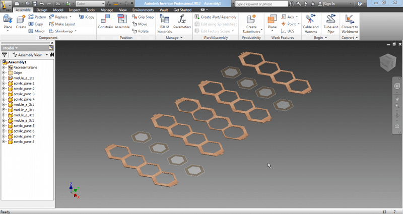
Then start assembling by using the "Constrain" and "Assemble" tools, which just put contrains on the different pieces. For example, putting a contrain that holds two faces of different pieces together.
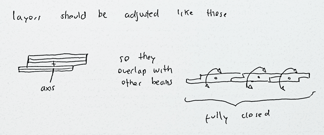
Each piece was design in such way that there are some prongs on the sides, that will be use to connect to the axis and thus get torque to rotate. Notice that the prongs make up a pattern.
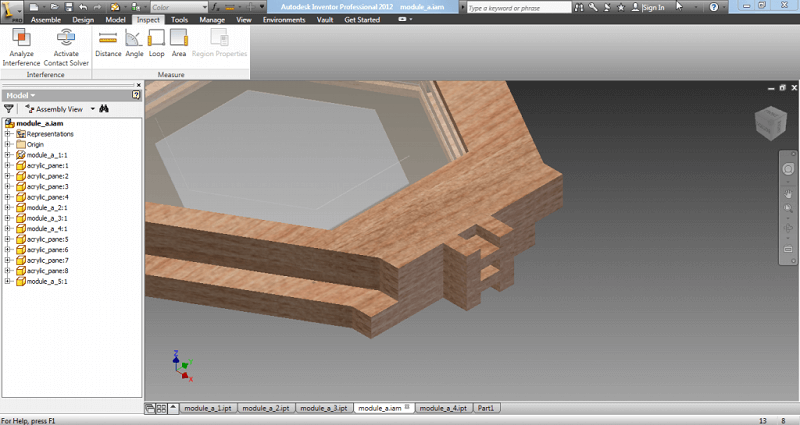
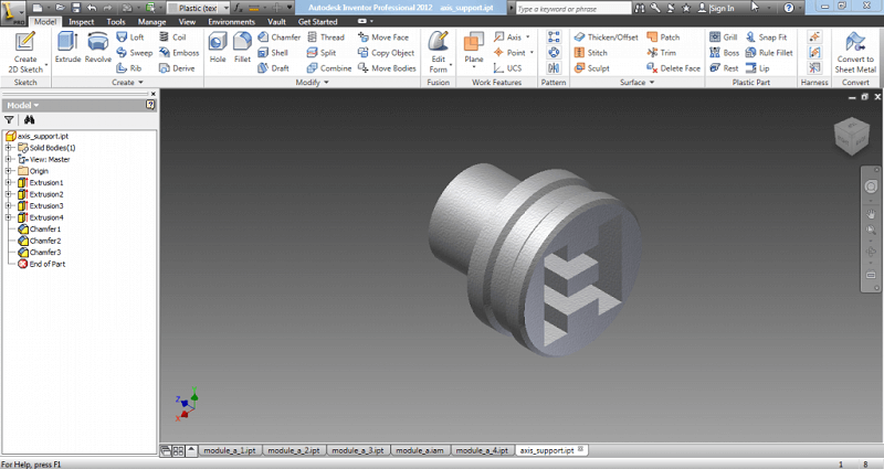
The same pattern was used to create a support piece that holds all the layers together, and that will be connected with gears to the motors.
Two of the previous pieces were placed on the assembly file, and correctly placed on both ends.
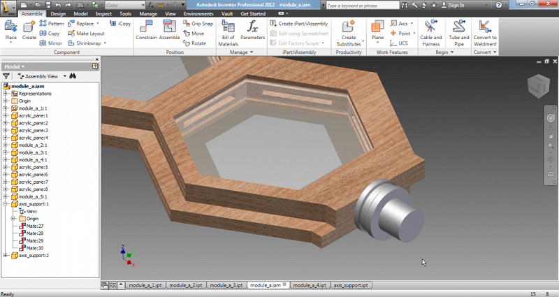
With that, Module type A is finished.
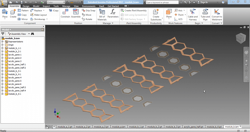
All the previous steps were reapeated to create Module type B.
All the previous pieces were designed to be used on the final project, with the modifications needed.
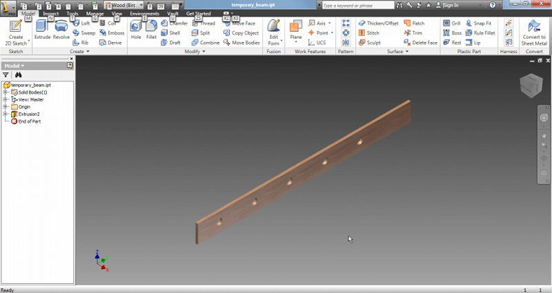
The following are just temporary, with the purpose of showcaing more or less how the Modules would look.
A simple longitudinal beam was created to hold the Modules.
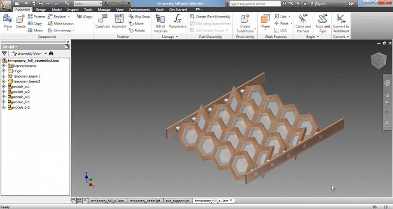
In a new assembly, I placed some copies of Module A and B (an assembly can be used for a bigger assembly) plus the beams.
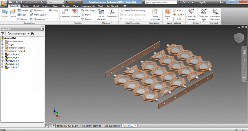
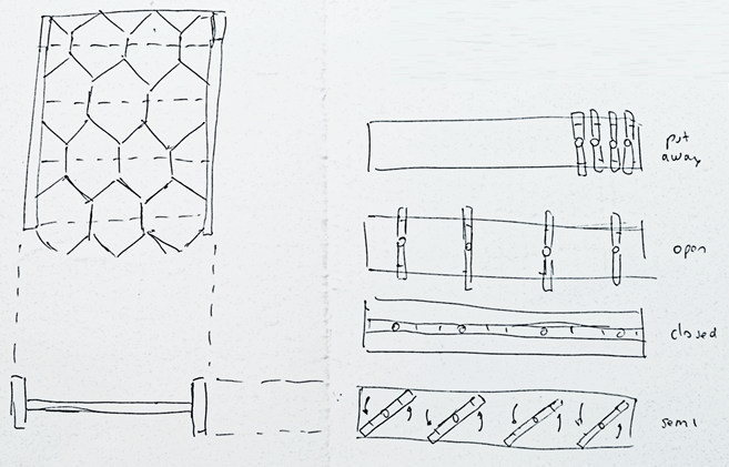
With some simple contrains I finished whis week's product.
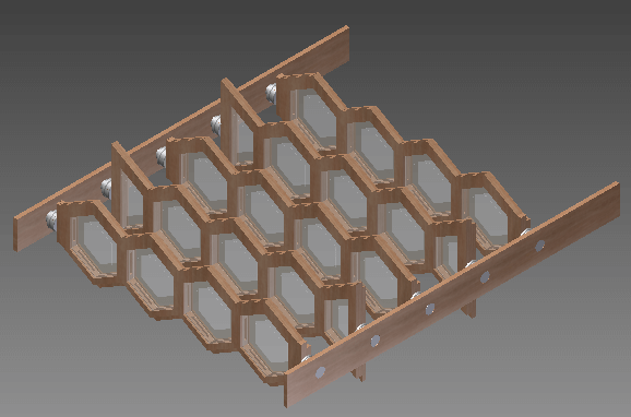
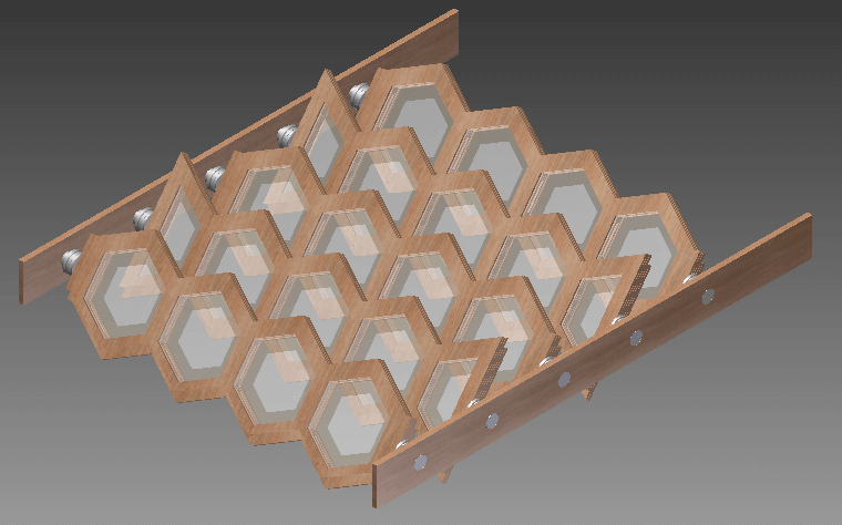
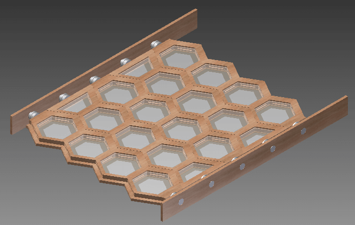
| FULLY OPEN | ANGLED | FULLY CLOSED |
 |
 |
 |