Photometric:
Robotically-Controlled Responsive Facade System
photometric from Kelly Zona on Vimeo.
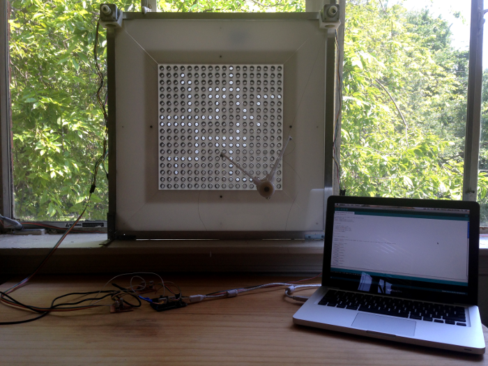 Final project with interface control
Closeup of screen
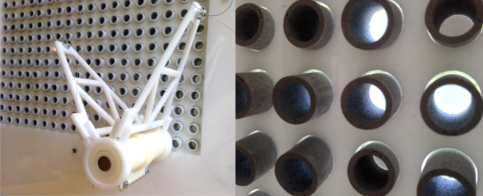 details
Overview
Photometric explores the emerging role of robotics in architecture, beyond tools for construction.
The project is a robotically-controlled responsive facade system that modulates daylighting levels, resulting in graphic visual patterns. It is an interactive work of art as much as it is a practical, low-cost display and sunshading system.
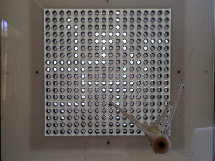
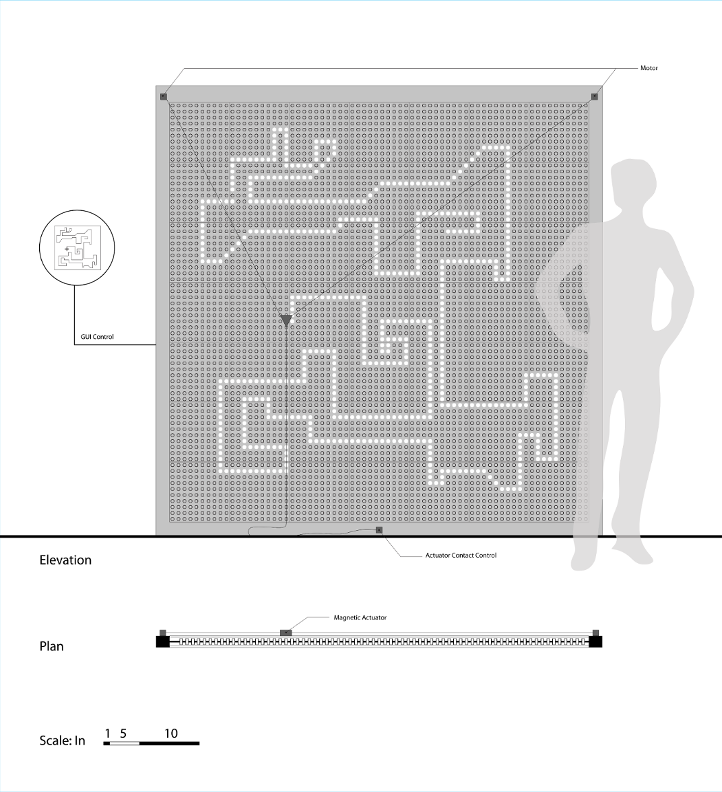
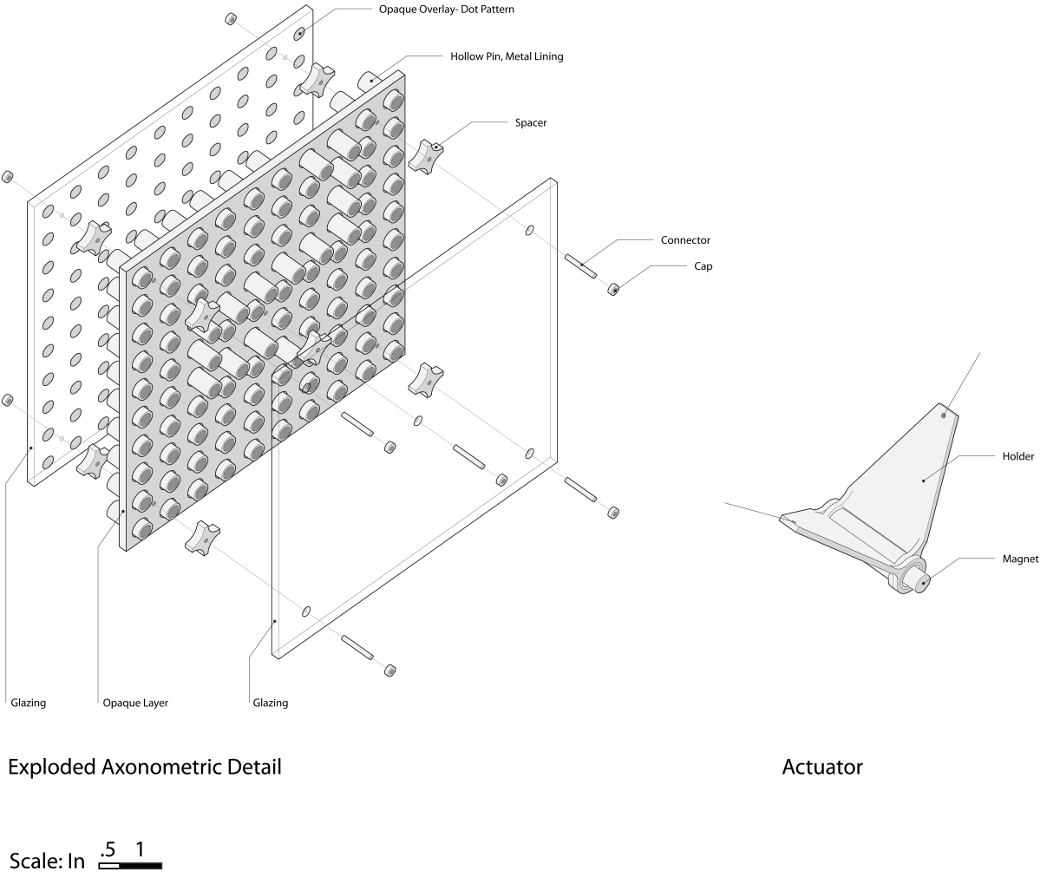
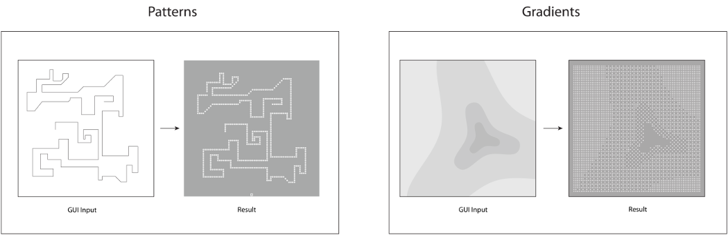
The system operates by digital user input; code is translated into patterns. A multi-layer screen is controlled by a magnetic actuator hooked up to two stepper motors. The screen consists of a perforated inner layer filled with freely-sliding hollow metal pegs. This inner layer is bound by two exterior layers of clear glazing. The back layer has opaque pattern of dots corresponding to the pegs. As the actuator moves across the screen’s surface, the pegs are pulled forward to their open position, generating patterns of natural light. A similar mechanism on the backside “resets” the pegs to the closed position.
Softly illuminated patterns of natural light gradually emerge from a blank canvas, and new patterns can be generated continuously. It is about the experience as much as the final result. The system emphasizes parametric performance over static parametric design
Drawings
x
Operations Diagram
Mechanics
Operation
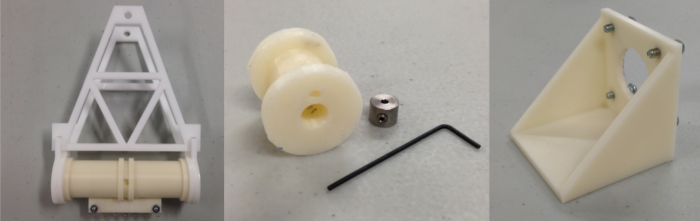
Mechanical Details
Fabrication
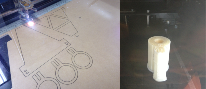
Laser-cutting and 3d printing of mechanical details
Files, Materials, & Specs
Actuator 3D Print and Laser Cut files
Miscellaneous hardware- McMaster-Carr
Stepper Motors- Jameco Electronics (standard Fab Lab inventory)
Epilog 40 Watt
1/4" Acrylic Sheet
Speed: 7
Power: 100
Frequency: 5000
Electronics & Coding
Interface
Testing the Fabduino. Uploaded a simple code to blink the LED.
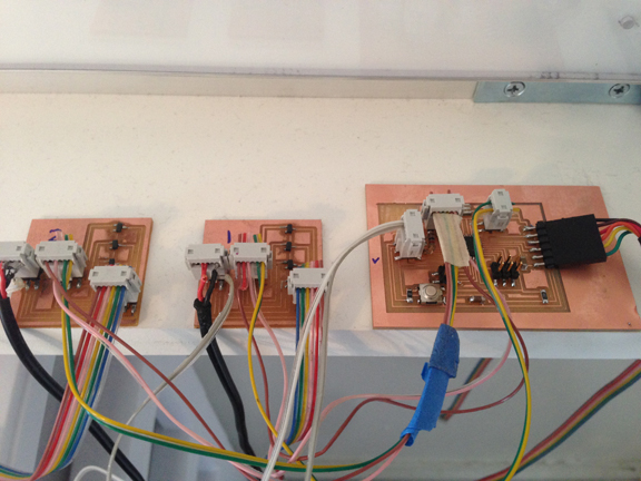
Testing the Fabduino and both stepper drivers simultaneously
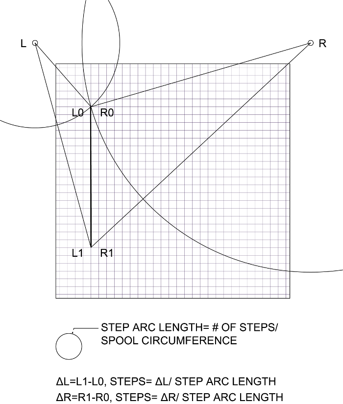
Operation logic
Design
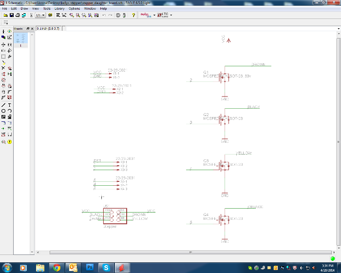
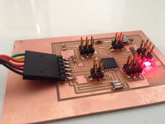
Stepper driver board design in Eagle
Fabrication
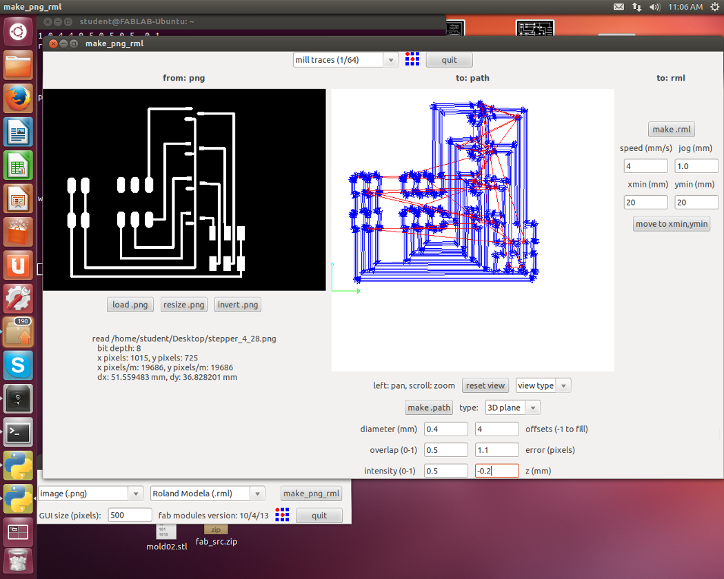
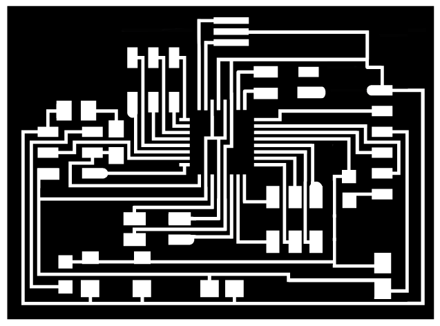
Milling the Fabduino and driver boards on the Modela MDX 20
Files, Materials, & Specs
Stepper Motor Driver schematic and board files available here
Fabduino Code (for blink test) available here
Code to run the Fabduino + Motor Drivers available here
Microcontroller board- Fabduino (main board)
PCB material and components- DigiKey (all components in the standard Fab Lab inventory)
1/64" bit
Diameter (mm): 0.4
Overlap (0-1): 0.5
Intensity (0-1): 0.5
Offsets (-1 to fill): 4
Error (pixels): 1.1
Z (mm): -0.2 (I found that -0.1 might not cut all the way through if the board is not perfectly level)
Speed (mm/s): 4
>Make Path
>Make rml
>Send It!
Screen & Frame
Assembling the screen, building the frame
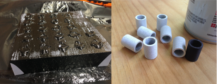
Casting and painting the pins
Files, Materials, & Specs
Screen 3D Print and Laser Cut files available here
Resin/metal cast pins- Smooth On (resin and silicon- standard Fab Lab Inventory), Alpha Chemicals (iron oxide)
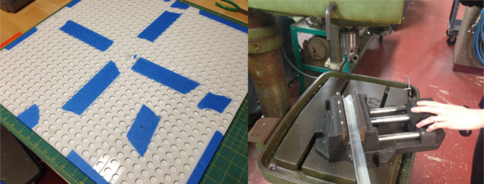
Laser Cutting
Epilog 40 Watt
1/4" Acrylic Sheet
Speed: 7
Power: 100
Frequency: 5000
Casting
To make the mold:
After printing the mold_2 .stl file, cast silicon rubber to create the mold
Smooth-On OOMOO 25
To make the pins:
Smooth-On Smooth Cast 305 & black iron oxide
Mix a ratio of 6 parts resin to 1 part iron oxide by volume