Final project
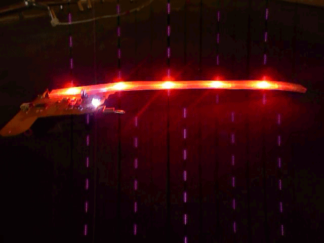
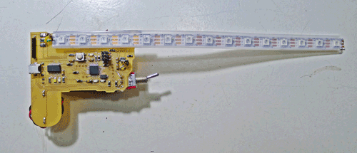
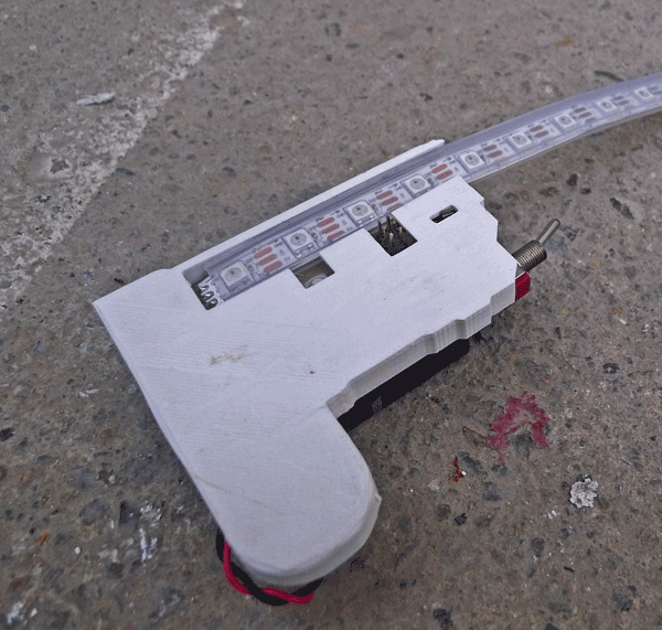
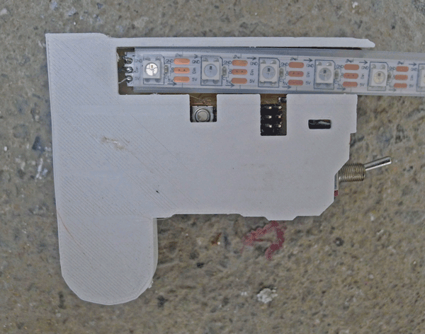
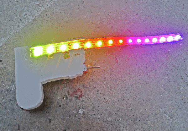
This is my final board with the longer led strip that measures the length of the spokes on my wheel.
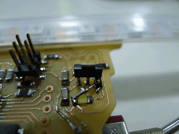
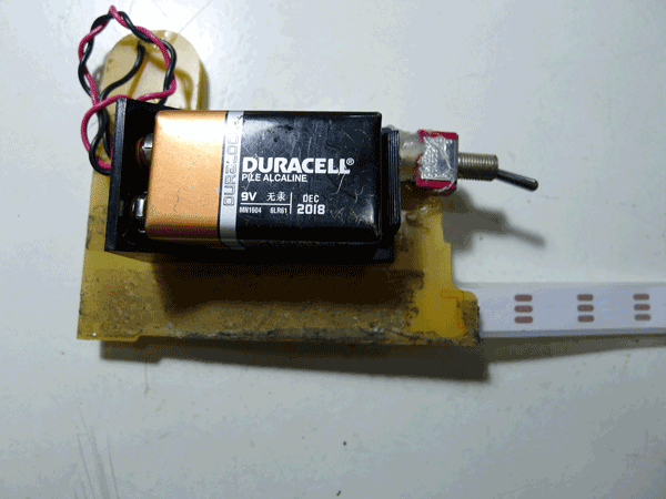
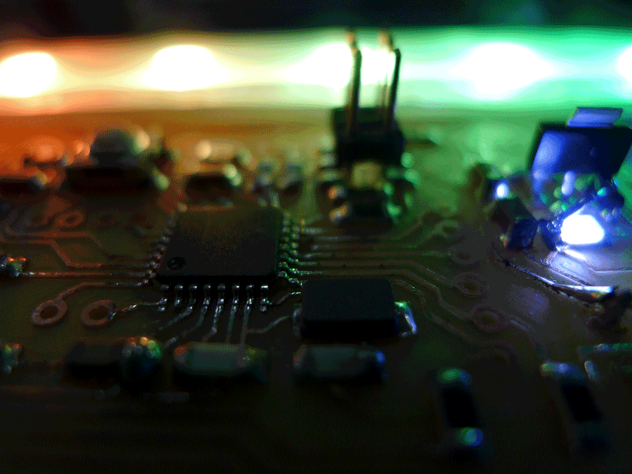
With the 5v 1 amp regulator /// And the 9v battery on the back
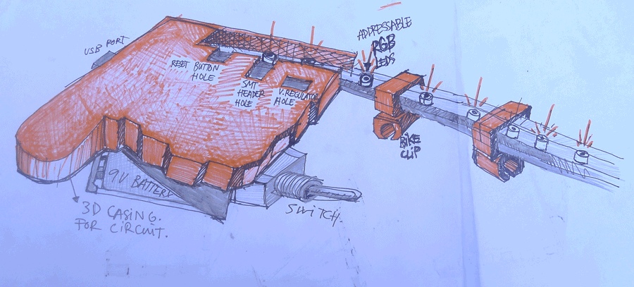
The final idea was to make a casing for the circuit in 3D by printing it on the replicator and also adding some clips to secure it on the wheel. I was planning on making the case and the spoke clips but only managed to make the main case as all the 3D printers we had at the lab where where broken or beeing used. I made a drawing to demonstrate how it would look on the board with all the pieces.
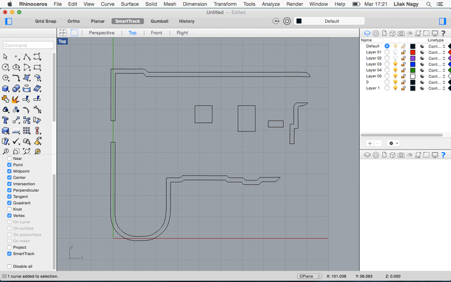
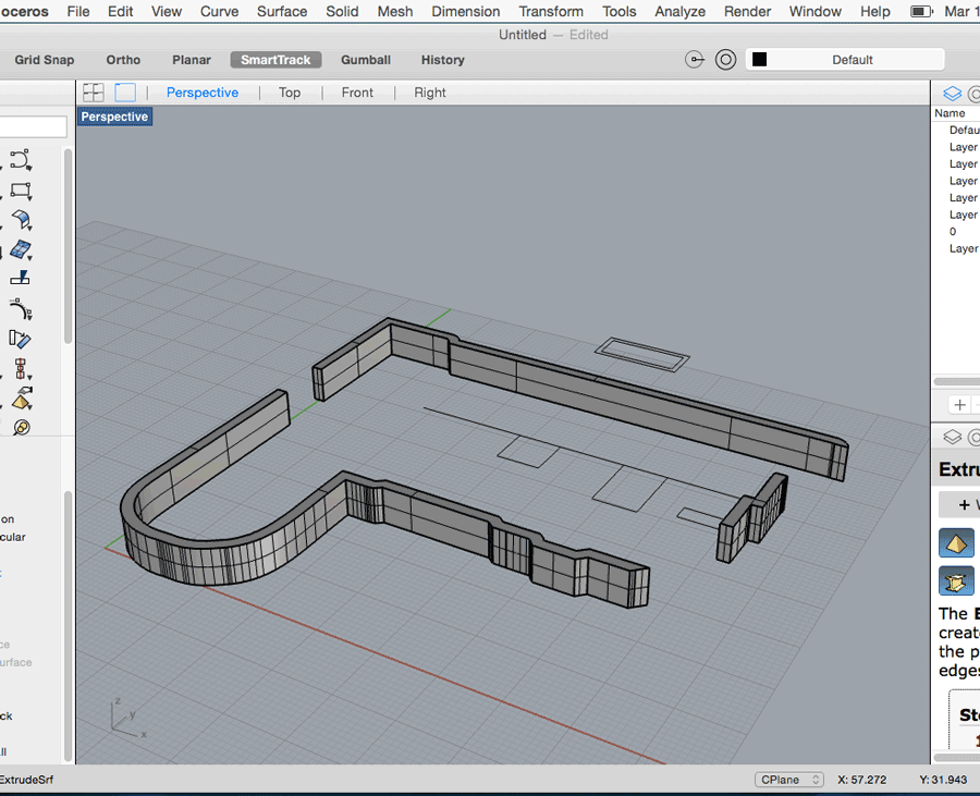
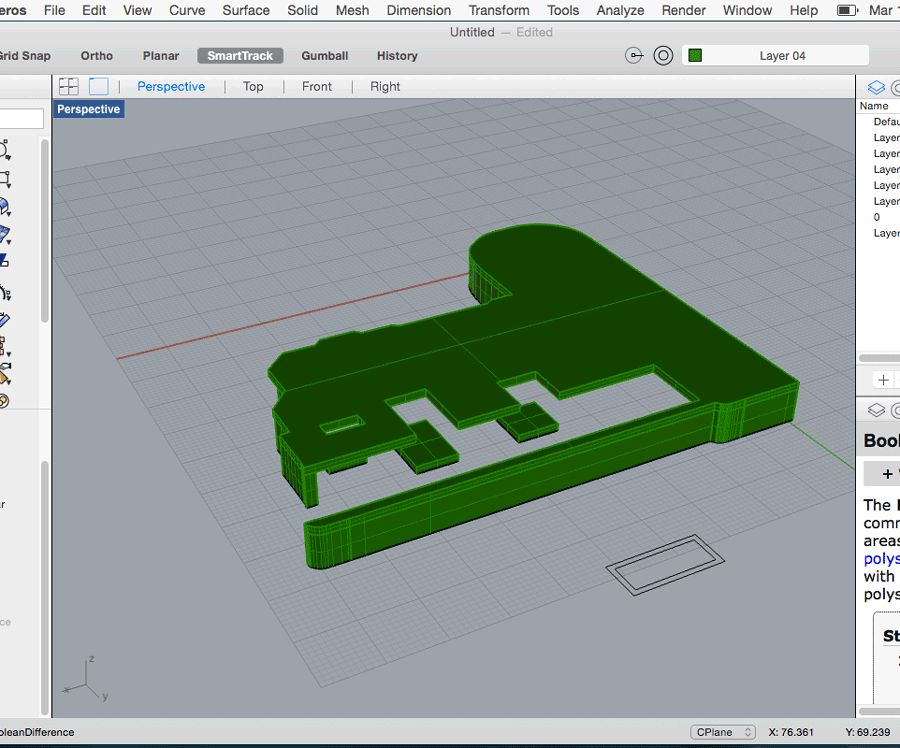
Here are some screenshots of the rhino files:
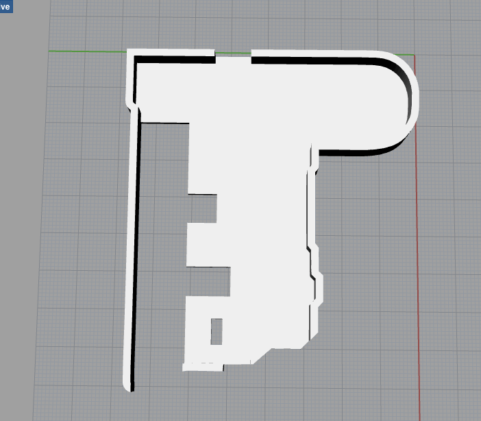
EXTERIOR OUTLINE
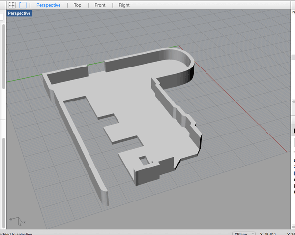
WALLS EXTRUDED
FINAL MAIN CASING
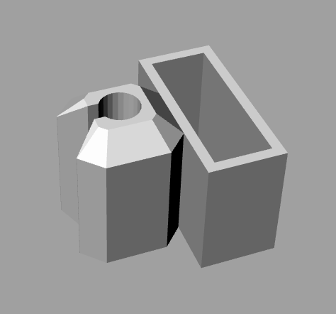
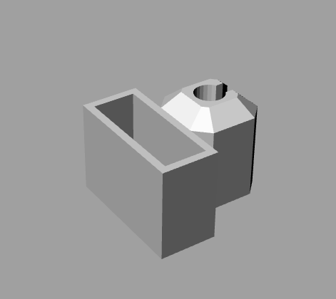
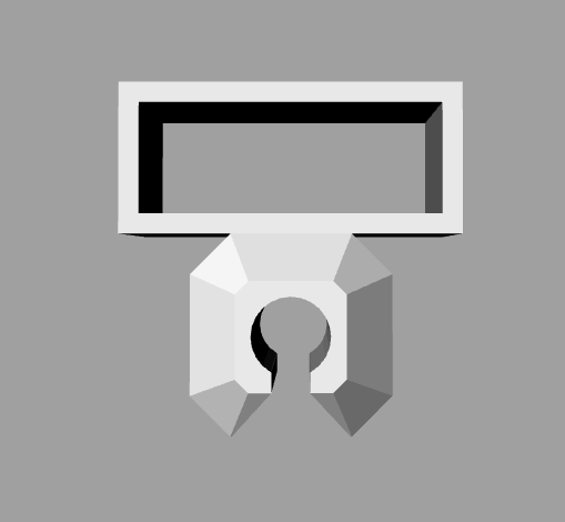
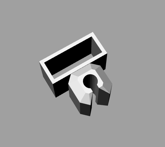
SPOKE CLIPS VIEWS
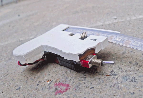
3D PRINTED CASING
And finally here is a short demosntration of the bike light on the wheel:
 THE DEVELOPMENT OF THE FINAL PROJECT IS LOCATED ON THE WEEK 19(click here)
FILES
· VERSION 1 PNG'S
· FINAL PNG'S
· KALEDUINO SCHEMATICS DESIGN VERSION 1
· KALEDUINO BOARD LAYOUT VERSION 1
· KALEDUINO SCHEMATICS DESIGN FINAL
· KALEDUINO BOARD LAYOUT FINAL
· BOARD CUT FILES FINAL
· RHINO CASING AND CLIPS FILE
· LIBRARY CODE NEOPIXEL · LIBRARY CODE POLULU