Concept
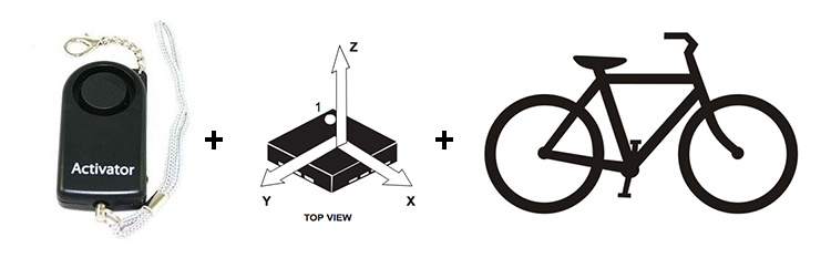
What I’m going to make basically is a bike alarm, to avoid that someone take your bicycle when you are not around. A simple bike alarm witch can detect movement, so if someone try to take it when the alarm is activated, a very loud buzzer will start play and another device that you carrie with you, wireless connected, will beep.
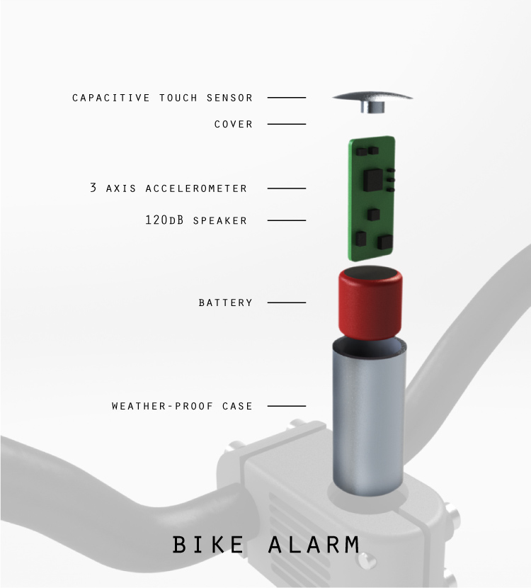
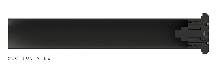
The idea is hide the device and use some kind of special bolt to avoid that the thief remove it when it starts to beep. Also a important point is how loud it will be. Well I'm thinking to use the same thing that are used in pull pin panic alarms, witch usually gives ~120dB (it’s enough to provide a uncomfortable environment in a 2m radius). To understand the rough idea, take a look in the picture below:
...for more information about my project proposal, please have a look at this page.
Project development
May 27 update
Since I will need to use an accelerometer sensor, I decided to start playing with one that is in lab inventory but is incredible small (LSM303C): I discovered that this is the new version of LSM303DHL and there’s nothing about it, no code’s examples, no eagle footprint, no board design example…and it’s so small that I cannot see if the pins are connected on the right trace. So by now I’m believing that it’s properly soldered, that my schematic design is correct, and trying to work on code, reading the data sheet. (By now I’m using this as a shield for Arduino, once I figure out how it works I will try to use with ATTINY).
June 03 update
After a couple of days of data sheet readings I finally manage to receive values from LSM303C accelerometer, with some help of Jani we figure out how to send the bytes to wake up the component and ask for the values. At the end, I’ve learned a lot about programming and soldering, so it was painful but it worth. Have a look in my first test with the accelerometer + speaker:
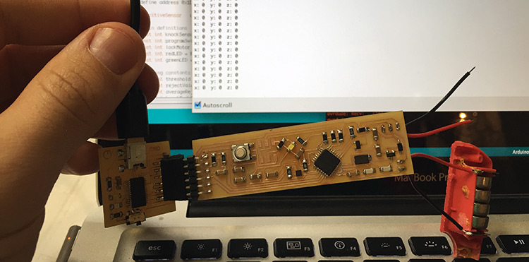
So next challenge is make a capacitive touch sensor to turn it on and off with a code sequence of touch. I found an example of knock knock locker using arduino + piezo, so I will try to use this with my capacitive sensor instead of a piezo. By now I’m using a Barduino and the accelerometer as a shield, just to program everything, once I finish the programming I will design a board with everything included and with the right size to fit inside of a steerer tube. This is how my board setup for programming looks like:
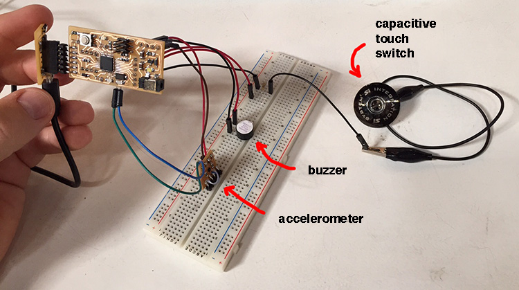
Download the code used in this example.
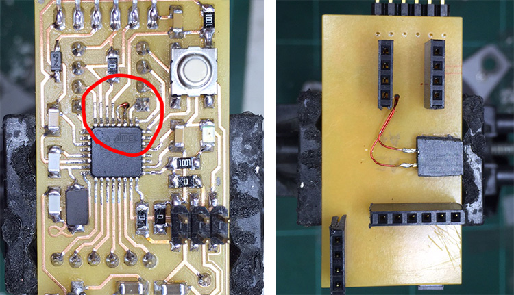
IMPORTANT: I'm using a 3.3V FTDI because Barduino only has 5V output and the Accelerometer maximum voltage is 4.7V.
I made two more connections in my Barduino because the original board doesn’t have the I2C pins connected, so I couldn’t use the accelerometer. Have a look how it was done:
June 17 update
I manage to make the setup works in a breadboard using my Barduino, of course there’s a lot of improvements to do in my code but, as I still need to design a board and a case and try everything together, for now it’s enough to move forward.
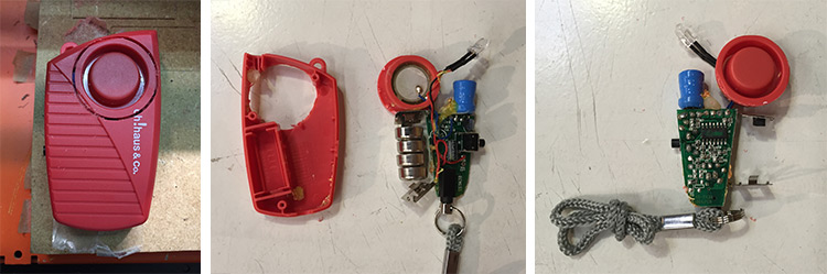
Next step was the alarm, so I found in a local store a pull pin alarm, witch is a very loud compact and portable alarm, and I bought it because I was curious to see how it works and to decide if I should reproduce it or just hack and use it.
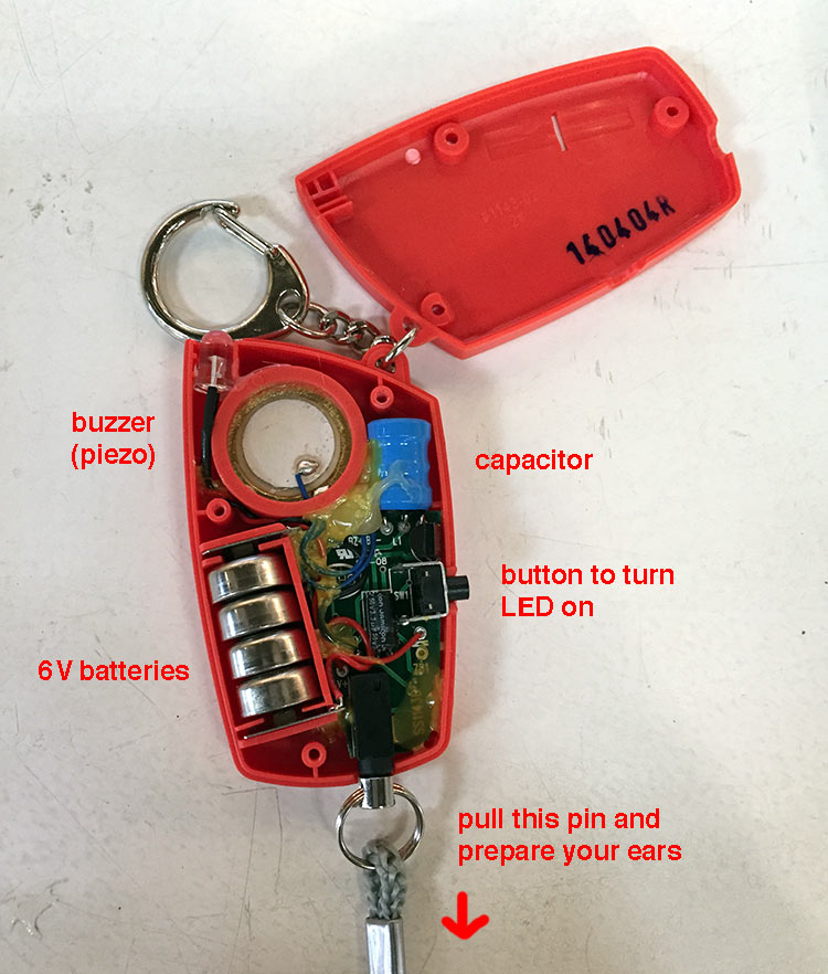
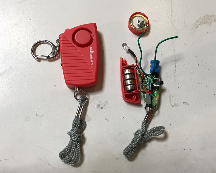
After teardown it I realize two things, first this is made basically with an oscillator, two big capacitors in order the get a higher voltage using only 6V batteries and a piezo to make noise. The second thing I realized after break the buzzer closure and remove the piezo. I barely could hear the noise without the plastic case. So the secret to have a loud noise with a piezo is the closure design because it works with a kind of resonance, and so after some google research I decided to buy a new alarm and this time keep the piezo closure save. Probably I could try to reproduce this design and 3D print it but since I didn’t have time the best choice to get a louder result is use this.
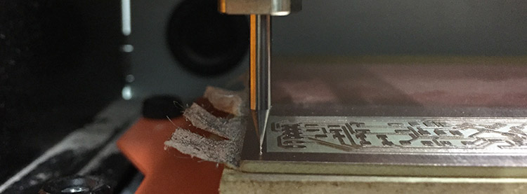
How could I remove only the buzzer closure since it belongs to the alarm box? Well the best solution was cut it using the Roland SRM-20 and a 1/32’’ milling bit:

Board design and production
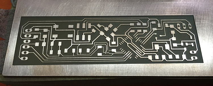
Board design was one of the hardest parts of my project because I had width limitations, once I must put it inside of the steerer tube. After a couple of days playing with eagle this is what came up:
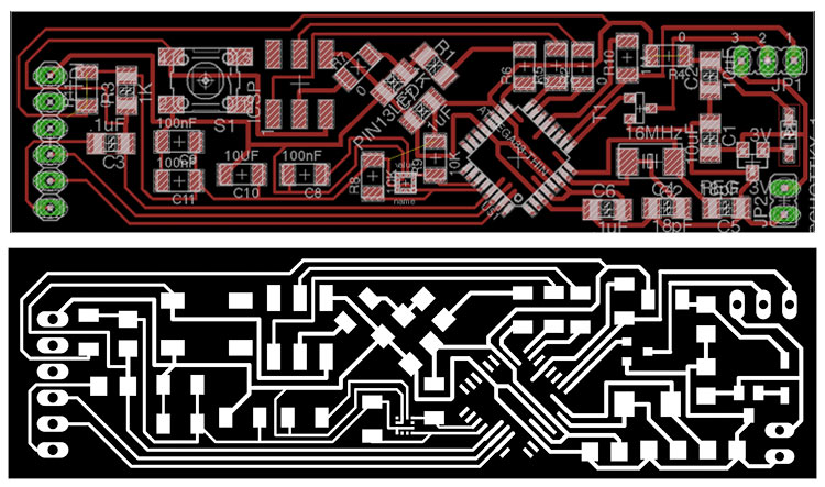
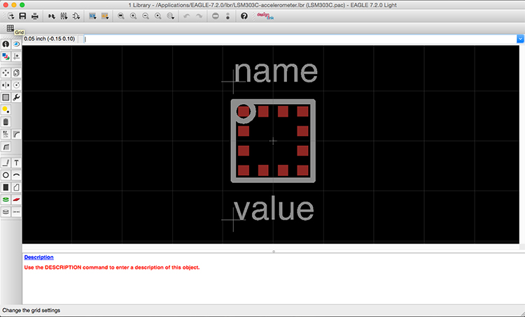
Also as I couldn’t found an eagle footprint for the LSM303C accelerometer I created a new library component following the dimensions of data sheet, and the instructions of this tutorial.
Check the BOM of components to make this board:
| Qty | Value | Device | Description | |
| 1 | 6MM SWITCH | OMRON SWITCH | ||
| 1 | DIODESOD123 | DIODE SCHOTTKY | ||
| 1 | JP1E | JUMPER | ||
| 1 | JP2E | JUMPER | ||
| 1 | LED1206 | |||
| 1 | NMOSFETSOT23 | MOS FET | ||
| 1 | PINHD-1X6 | PIN HEADER | ||
| 1 | PINHD-2X3-SMD | PIN HEADER | ||
| 3 | .1uF | UNPOLARIZED_CAPACITOR1206 | unpolarized_capacitor | |
| 6 | 0 | RES-US1206FAB | Resistor (US Symbol) | |
| 3 | 100nF | CAP-US1206FAB | ||
| 2 | 10K | RES-US1206FAB | Resistor (US Symbol) | |
| 1 | 10UF | CAP-US1206FAB | ||
| 2 | 10uF | UNPOLARIZED_CAPACITOR1206 | unpolarized_capacitor | |
| 1 | 16MHz | CRYSTALCS10 | CRYSTAL | |
| 2 | 18pF | UNPOLARIZED_CAPACITOR1206 | unpolarized_capacitor | |
| 2 | 1K | RESISTOR1206 | ||
| 1 | 1M | RES-US1206FAB | Resistor (US Symbol) | |
| 1 | 3V | REGULATORSOT23 | Voltage Regulator 3V | |
| 1 | - | ATMEGA328P AU | ||
| 1 | LSM303C | LSM303C | Ultra-Compact High-Performance e-compass 3D Accelerometer and 3D Magnetometer Module |
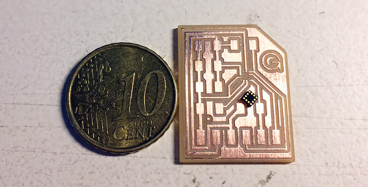
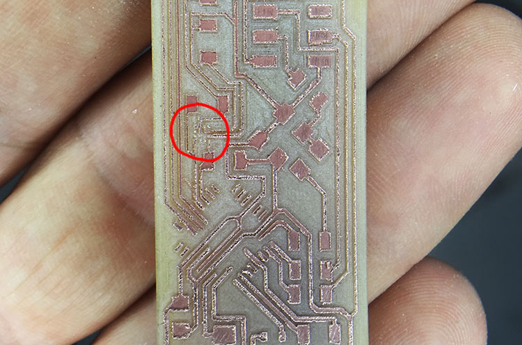
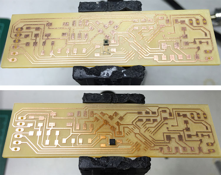
Milling this board was quite hard as well, since I’m using some routes with 0.254mm, in order to connect the LSM303C accelerometer, the 1/64” milling bit is too big. So first I tried with a ‘’half broken’’ 0.1” bit that still works to cut, for example, pads for ATMEGA 328, but since it was not sharp enough the result was terrible and some of the accelerometer traces gone during the process:
Second try I asked for a new 0.1’’ milling bit, witch is very fragile, and I knew that if I use with the same setup for the 1/64” bit it would break in the first 5 seconds. So what I did step by step was this:
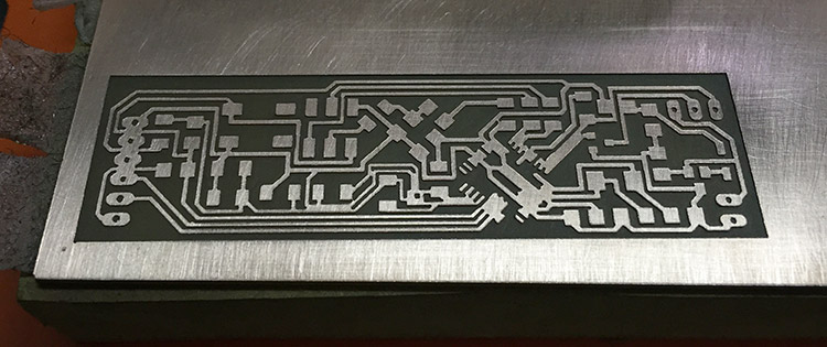
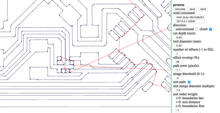
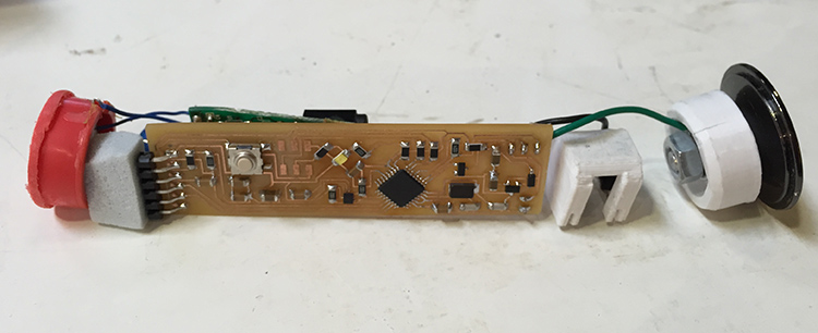
Final result:
Soldering and programming
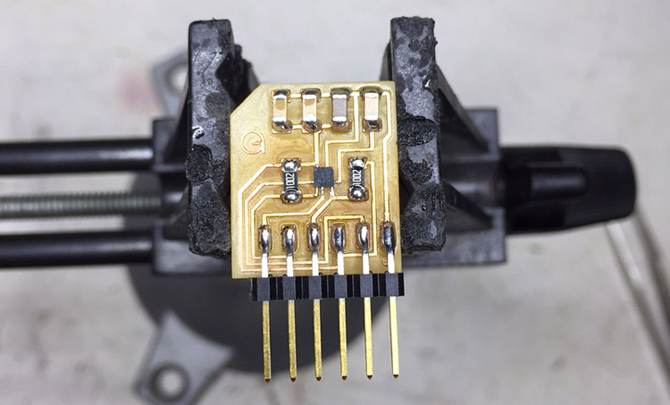
After milling I started soldering by the accelerometer. Since it has 2mm2 and 12 pins underneath I decided to use solder paste to do it. My method was first use a needle to spread the paste over each pin and then drop the component in the right position. Then use heat gun to melt the paste and solder the component.
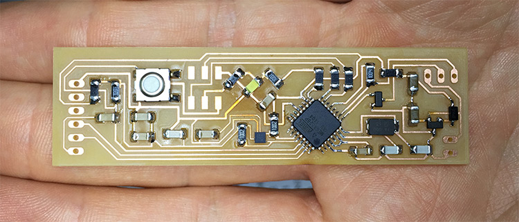
Since I don’t have much space in the alarm case I decided to not solder the programming jumper, because it’s only necessary to burn the bootloader. So I burned it only holding and pressing the jumper against the board, and it surprisingly works.
The accelerometer didn’t work in my first try, so I heated it again, removed it, and did everything again with the needle and solder paste. This time I putted more solder paste and the heat gun underneath the board. The problem is that you only knows if it is in right position when you program it.
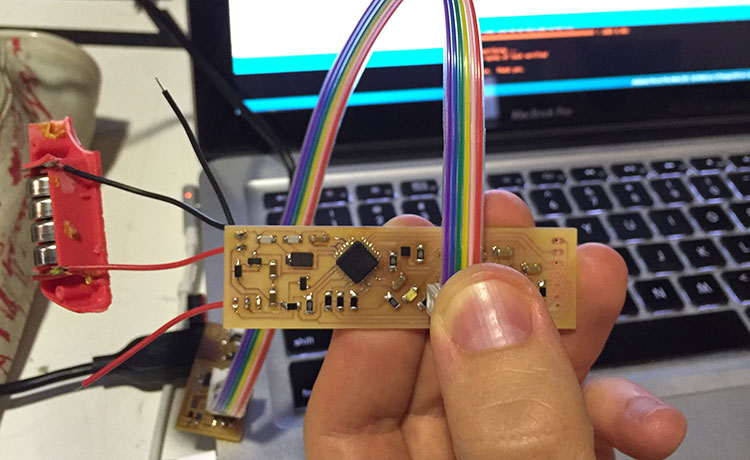
Now everything working, so I just uploaded the code using Arduino IDE. And then I made some changes and added some filters in the code to calibrate the capacitive sensor and the accelerometer. You can download it in the end of this page. Is important to say that this board doesn’t have a power supply connection from FTDI, so to program it you must power it, I’m using a 6V battery, in this case.
Case design
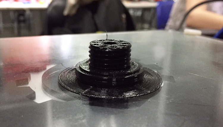
For the case first I designed something very simple to 3D print, because I would like to see how it will be printed since I was using 1mm thickness wall in a very tall model.
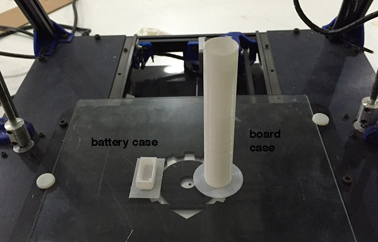
The result was good, but a few layers came out bad and at the end it broke. Also my board didn’t fit inside, so I ended up presenting my project without a case. Just some parts 3D printed to hold the batteries and to have a cover. (I’d been trying to find a PVC or steel tube to buy and use as a case but unfortunately here in Barcelona they have some dimensions standards, and so I was looking for 24mm outer diameter but they only have 20,22 or 25mm). So this is how I presented:
have a look in my presentation slide.
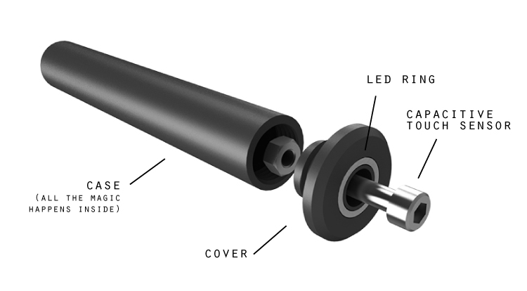
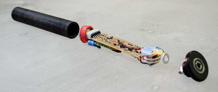
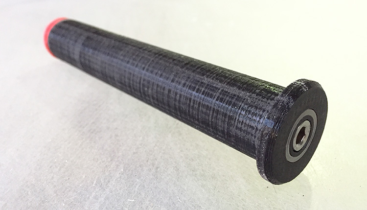
After the presentation I kept trying to solve the case problem. So I designed another version with thinner wall (0,8mm) and I printed in a RepRap BCN3D+ using black PLA.
I made also a cover with a transparent ring on top, that allows you to see the LED feedback when the case is closed, it makes the capacitive button easier to use.
How to install it in your bike?
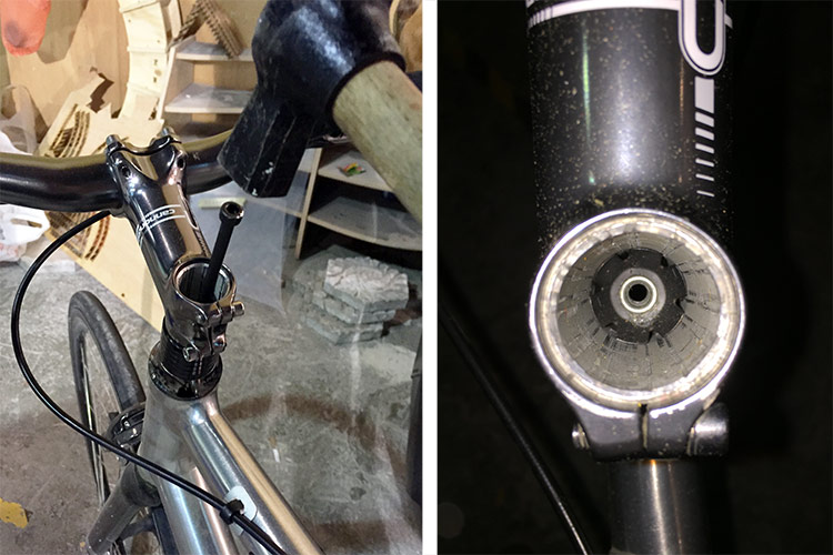
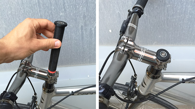
It’s easy, every bike that has the threadless headset, (what is the difference between threaded and threadless?), has a free space inside of the steerer tube, witch is the steel tube that connects your fork with your handlebar. And so, the only thing that is inside of this tube is a star nut but you can push it down a bit to open space for the alarm. And afterwards, you can just use a bigger screw. So, let’s do it: (I bought a M6 x 170mm socket cap screw to push it down)
Download here all the files to reproduce this project. In case you miss something, please feel free to contact me.
| File | Material | Machine |
|---|---|---|
| board design (eagle files) | - | Roland SRM-20 |
| code (Arduino IDE) | - | - |
| case (body+cover) | PLA (black) | RepRap BCN3D+ |
So, at the end, I’m happy with my final project result, it works! : ) And also because now I can see that I learned a lot during the course, and I can feel more comfortable doing things that I had never tried before, like electronics and programming, for example.
And now I listed some things that must be done, in the future, to make my project more usable:
To do:- Make the case weather-proof.
- Fix the alarm in the bike somehow that you can also remove it to change the batteries, but only with a special tool or something like this.
- Program in a better way to less consumption.
- Use the function that allows to program a new unlock sequence on capacitive button.
- Use all the axis of the accelerometer to make it more accurate.