Théo Lepage-Richer

Fab Academy / Digital Fabrication 2015

Modeling and Cutting a Brutalist Construction Kit

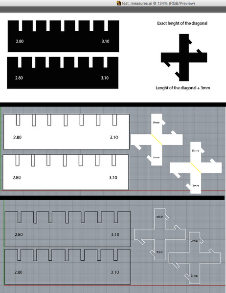
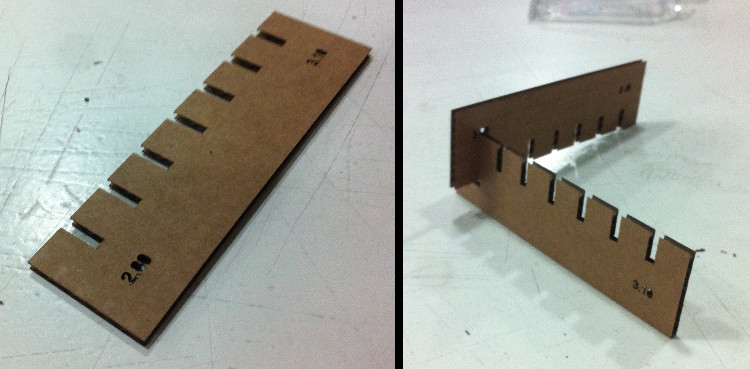
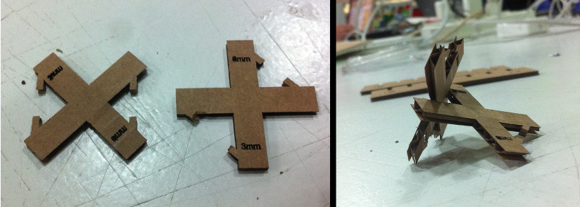
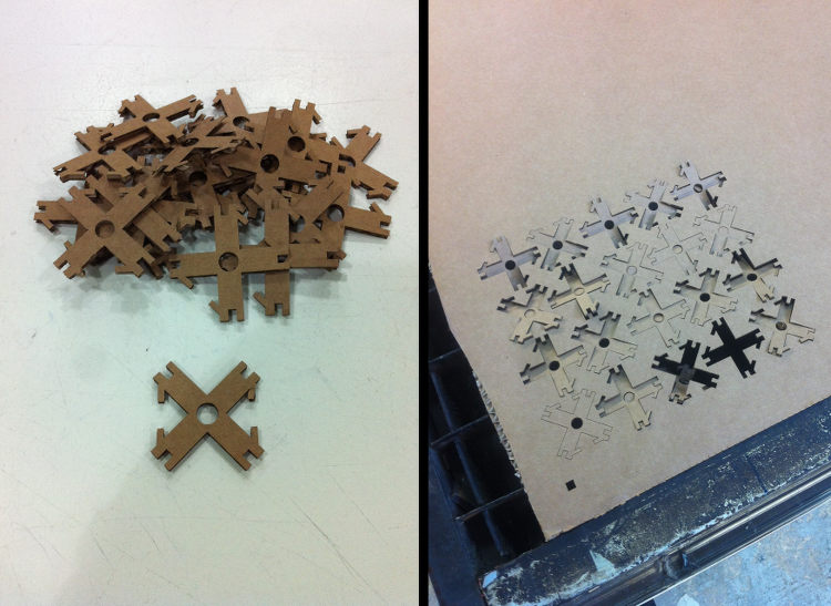
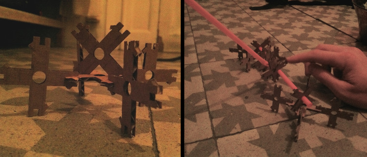
This week started off with Neil’s invitation to first design a construction kit before building anything else and Ferdinand’s emphasis on the importance of testing the material before designing anything else. I therefore decided to start by drawing 1. a little measure tool to evaluate the ideal size of the gaps used to imbricate two pieces together and 2. a first draft of my construction kit piece. Regarding the latter, I decided to take Neil’s invitation quite literally and tried to imagine a single piece that could allow for as many combinations as possible. In my case, my piece could attach itself to another one both linearly and perpendicularly, as well as rotate around and attach itself to a straw.

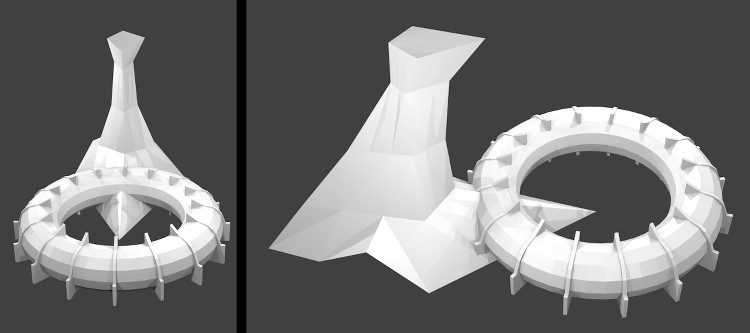
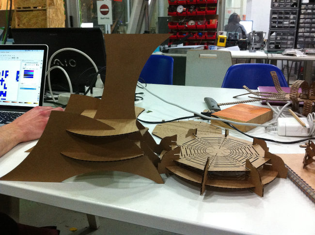
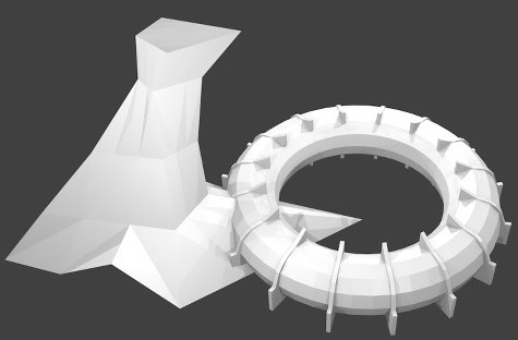
After having completed this first exercise, I decided to do a little homage to one of Montreal’s greatest pieces of brutalist architecture – its Olympic stadium. Of course, its look is not as ‘brutal’ as the Londoner tower blocks that pretty much sum up this movement’s legacy for me – as playfully illustrated by these small buildings kits – but Montreal’s Olympic stadium has become for Montrealers a powerful symbol of the city’s often aggressive architecture. Yet, some of them – including myself – ended up liking it, and now proudly present Montreal as the most beautiful, ugly city there is.

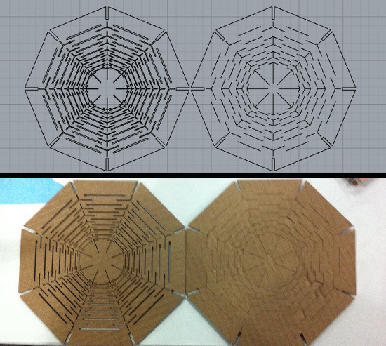
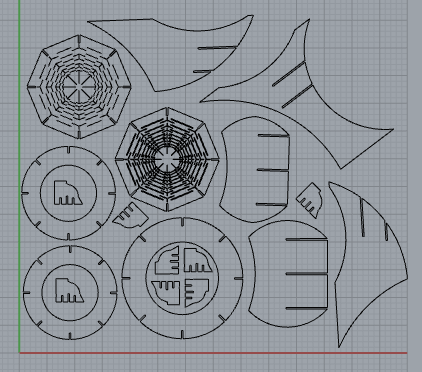
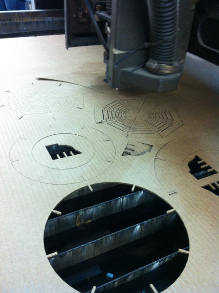
The piece itself wasn’t too hard to design per se – even though making precise measurements in three dimensions made me realized that I really don’t get ‘space’ – but sure was time-consuming. I first tried to directly draw everything in 2D, but quickly realized that I couldn’t get very far with a general visualization first. In the end, I did accumulate a fair amount of drafts in various formats – struggling first with the tower, then spending ages trying to design a satisfactorily flexible roof – but nonetheless ended up with a decent result (‘learning experience’-wise, as opposed to ‘pretty enough to make one’s mother proud’-wise).

See below for all the details/for each step.

Your Name

  • Week: 03
  • Subject: Computer-Aided Cutting
  • Tools: Rhino, Blender & Illustrator
  • Objective: Designing and building the basic pieces of a construction kit, and then develop any other project tackling the possibilities afforded by computer-controlled cutting
  • Files: Click here

Project 01a
I first used Illustrator to draw my ‘measure tool’ as well as the first prototype of my construction kit unit – at this point, I was trying to evaluate the right distance between the center of the piece and its lateral edges in order to ‘lock’ two pieces perpendicularly – but quickly ran into few problems when I tried to actually print my pieces. Illustrator indeed has the advantages of working with real world units of length but I still had to pass my files through Rhino to transform surfaces into polylines, get rid of overlapping lines… clean up everything to put it simply.

Laser Cutting: First Attempt from Theo L. Richer on Vimeo.

The machine itself was surprisingly easy to use, despite my extra care to not set anything on fire. Watching the machine in action was actually pretty impressive, but it is clear that laser cutting is far from being trivial and requires constant attention to avoid any accident.
Project 01b
I was expecting few burns as it was my first time using such a machine, but my set came out very neatly. I first tried to evaluate the ideal size for the cuts, which, as the cardboard was supposed to be 3mm thick, I thought would be around 2.90mm. Yet, even the smallest one I had made – 2.80mm – seemed too big and allowed for a lot of movement between the pieces. I therefore figured that, for the cardboard we have, 2.70mm would be the ideal size.
Project 01b
Regarding my construction kit unit, the perpendicular snap worked quite well – even though I doubt that one could put another piece in and out more than two or three times without breaking it.
Project 01b
Based on what I learned with these first steps, I made a first prototype with the right length, the right gaps and wholes in the middle to make structures with straws and the like. The cutting went neatly and I then proceed to make my first 'structures'.
Project 01b
I quickly realized that the cardboard wasn't strong enough to support minimally elaborate formations and too stiff to allow for vaguely distorted structures. Yet, as I was actually expecting these outcomes, I was nonetheless happy of the wide range of interactions that my single piece allowed for - lateral locking, perpendicular locking, rotation around a straw, locking a straw in a given position, &c.
Project 01b
After having finished this 'construction kit', I started working on my model for which, I have to admit, my workflow was a bit of a mess. I first made a 3D model of it in Blender, but quickly struggle to translate it into a 2D plan. I then did a little tabula rasa and started all over in Rhino, drawing directly the plans in 2D (which probably explains the proportion issues that I will become evident below).
Project 01b
Designing the whole thing was idea a big exercise of spatial visualization (which I am not especially good at), but one of my main interests in this process was to imagine how to develop a flexible roof. The roof of Montreal's Olympic stadium is actually a big canvas, so I made to two tests to 'reproduce' its malleability. The one on the right ended up having a higher range of movement, but solely on its main axis, while the one the left had a general flexibility on all its surface that made it the most interesting option.
Project 01b
The final plan ended up being a collection of 18 pieces. I designed the torus in Illustrator as I initially found it more intuitive, but I quickly ran into complications when I tried to draw the tower, which required a more accurate understanding of the 3D interaction between the parts. I therefore drew the tower in Rhino as well as exported the torus in it to refine it.
Project 01b
At this point, everybody was rushing around the last cutter and the thing became kind of a rat race, but the cut went smoothly and I was relieved to see that all the details of the roofs came out clearly. I picked up all the pieces and finally brought everything together to realize that the model looked...
Project 01b
... absolutely terrible. Not only was the proportion between the tower and the torus completely off, but this difference was made even more explicit by my miscalculation of the torus' circles. Only the main one could fit while the other two that were supposed to give the structure its rounded shape were way too small to be hold within the structure. I now realize that I should have made my project using a single software tool and built a new 3D model of my project on Rhino when I failed to make use of the one I had made in Blender. Even though I didn't have the time to make a new version of it, I was nonetheless happy to have resisted to the 'easy way out' which would have been to use 123D MAKE - a software that basically translates any 3D model into ready-to-cut board. In that sense, this whole project was indeed a great practice of visualization - which we had already explored last week - but its main interest was mostly as an first step towards 'digital translation', i.e. of making use of these visualizations and turn them into physical objects. I might not have the greatest sense of spatial perception, but I now have a better idea of how to 'map' my projects.