final project development
conclusio
the whole experience of the fabacademy was extraordinary on many levels. it was a technical but also a deeply personal challenge and better than expected. at this point i want to thank especially tomas, ferdi and santi, for their patience, stamina and helpfull insight into an unknown world that we are about to create. also it was a pleasure to work with the people from all over the world, coming to barcelona to share their knowledge and the experience of doing this academy. thank you all!!
this page follows the development of my final project from the end to the beginning.
File
download the files
programming
after not being able to make the SD card work, even by trying several different approaches, i will go into programming the underlying idea of the tracker, recording the exact date and time whenever the toggle swith is being activated.
arduino ide
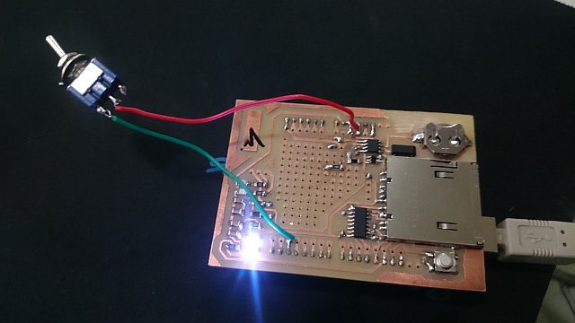
to begin with i used an arduino uno with my shield. first i wanted to make sure that the button is correctly wired and all the soldering works nicely. so i used the arduino button example as a reference. Unexpectedly it didn't work from the beginning so i checked the soldering with a multimeter and found out that some of the connections were not working. back to soldering - then it worked fine.
input: pin 2
output: pin 13 (as on the arduino also the shield comes with a built in led)
toggle switch + RTC
the challenge was to combine the toggle switch with reading the time every time it switches position. to achieve that i took the rtc code from the arduino RTClibwhich needed to be installed first.
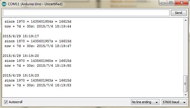
// Date and time functions using a DS1307 RTC connected via I2C and Wire lib

#include <Wire.h>
#include "RTClib.h"

RTC_DS1307 rtc;

const int switchIn = 2;
const int ledPin =  13;
boolean switchState = false;
boolean lastSwitchState = true;

void setup () {
  Serial.begin(57600);
  pinMode(switchIn, INPUT);
  pinMode(ledPin, OUTPUT);
#ifdef AVR
  Wire.begin();
#else
  Wire1.begin(); // Shield I2C pins connect to alt I2C bus on Arduino Due
#endif
  rtc.begin();

  if (! rtc.isrunning()) {
    Serial.println("RTC is NOT running!");
    // following line sets the RTC to the date & time this sketch was compiled
    //rtc.adjust(DateTime(F(__DATE__), F(__TIME__)));
    // This line sets the RTC with an explicit date & time, for example to set
    // January 21, 2014 at 3am you would call:
    // rtc.adjust(DateTime(2014, 1, 21, 3, 0, 0));
  }
}

void loop () {
  switchState = digitalRead (switchIn);
//  Serial.println(switchState);
//  Serial.println("lastSwitchState");
//
//  Serial.println(lastSwitchState);

  if (switchState == 0 && lastSwitchState != 0) {
       // turn LED on:
      datum();
      digitalWrite(ledPin, HIGH);
  }
  else {
    // turn LED off:
    digitalWrite(ledPin, LOW);
    lastSwitchState = 0;
  }
  lastSwitchState = switchState;
}

void datum (){
    DateTime now = rtc.now();
    Serial.print(now.year(), DEC);
    Serial.print('/');
    Serial.print(now.month(), DEC);
    Serial.print('/');
    Serial.print(now.day(), DEC);
    Serial.print(' ');
    Serial.print(now.hour(), DEC);
    Serial.print(':');
    Serial.print(now.minute(), DEC);
    Serial.print(':');
    Serial.print(now.second(), DEC);
    Serial.println();
    }
this is what came out as the working code! nevertheless i was looking at other possibilities as for example using interupts. i tryed the example code and made it work but you need a debunce, because if the toggle switch is being activated the interiour mechanics might bounce, giving two signals, which in the end confuses the microcontroller of the arduino.
trouble shooting
on the way of making the data logger shield work, i had a variety of troubles coming my way.
hardware
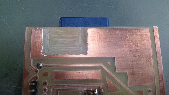
for saving time i didn't mill away all the copper. when plugging the shield into the arduino uno, the usb connector touched the copper of the shield. for safety i removed the copper with a drill. the same thing happened around the battery clip.
RTC
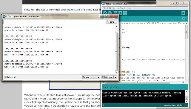
for testing the real time clock (RTC) i followed the tutorial on the adafruit website, the are also the libraries needed for the arduino. after putting in the battery and connecting the arduino with the shield to the computer i started arduino. i had to choose the right port and the right arduino.
first after uploading i got only nonsense in the serial monitor. that was because the baud rate was set to 9600 but needs to be 57600 as in the code.
the following issue was that the time didn't change at all and the response was that the clock is not running.
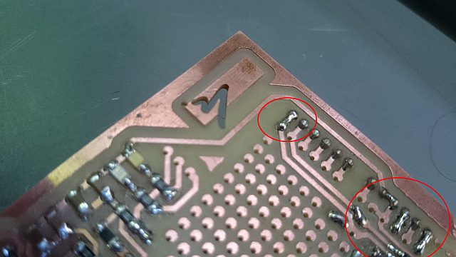
after testing the connection with a multimeter i found out that some traces were not connected with the back of the board / missing vias. so i went back into soldering some vias, repeating the procedure described in the tutorial and...
... it worked!
SD card
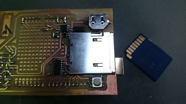
i started with a no name card with 2GB, despite the warnings in the tutorial. so to begin with i formatted it directly in the explorer, put it in the slot, connected everything, uploaded the example code from the libraries. the card wasn't even initialized. so i went to use the formatter from the SD association. it didn't work...
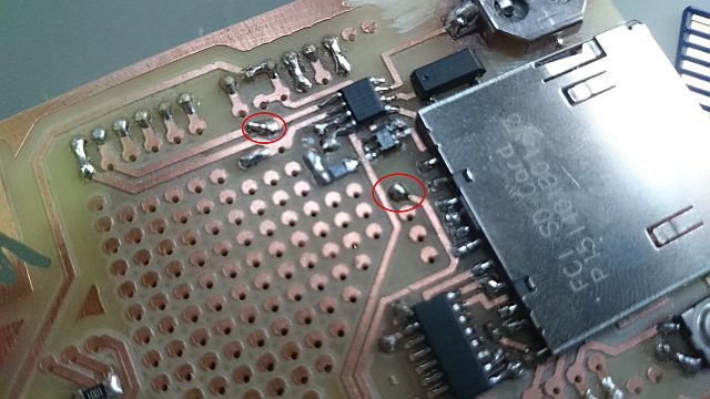
again there where some vias missing wich i replaced. still it didn't work...
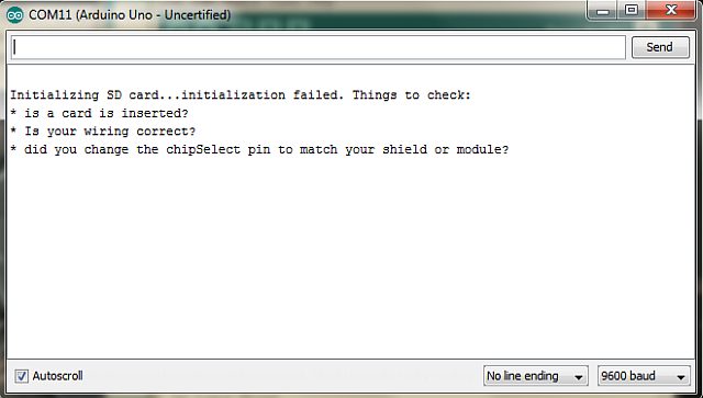
giving me this error message.
so finally i repeated all the steps above with a different card: no success either. since time is tight, i will move on to programming the toggle swith, making the time stamps with the RTC.
data logger shield & double sided milling
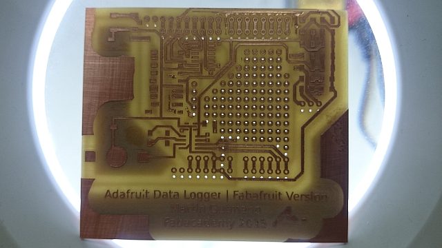
i spent quite some time researching possible data loggers. the most interesting thing to do for me is to make a fabable version of the adafruit data-logger shield for the arduino uno, it will give me the oportunity to reuse it later rather than producing different parts which are individual. the following devices are included in the shield:
input: any sensor plus a real time clock (RTC)
output: an SD card reader/writer
since the
eagle file from github has different (smaller) components i replaced them with the ones from the fab inventory and i had to rewire the SD slot because the cd-pin (card detect) is different from the one i used.
since the whole thing is rather complex i went for double sided milling of the board.
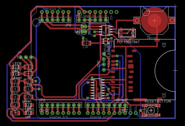
an eagle screenshot. i later added more vias to be able to solder different sensors to the board.
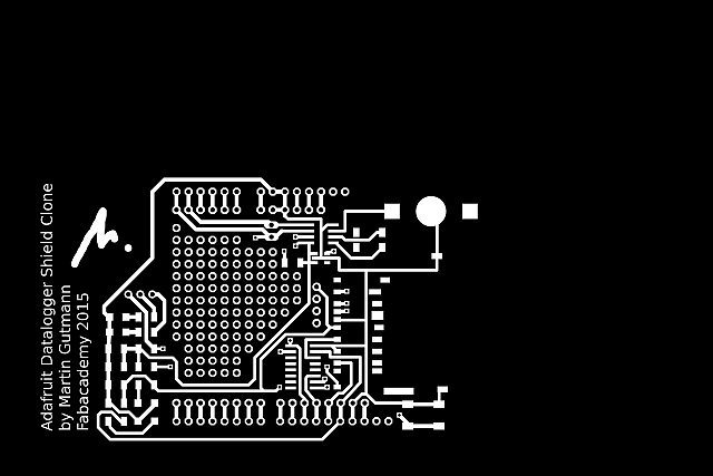
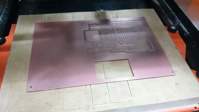
the top of the board. since i had to flip the board, the sice of the image had to be exactly the sice of the pcb.
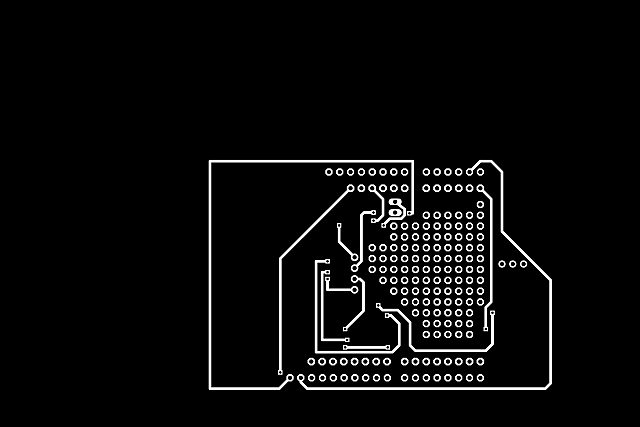
the bottom. since i flipped it over a vertical axis it is on the other side of the drawing

in the end i did the holes and the cutout.
double sided milling
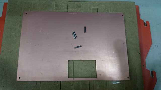
first of all the canvas in the drawing program needs to be the same sice as the pcb. to get prepared you need to make a drawing with four holes in the corners.
the holes have to have the same diameter as the pins and the cut depth has to be the same as the length of the pins. (it needs to cut into the sacrificial board, so make sure it's thick enough!)
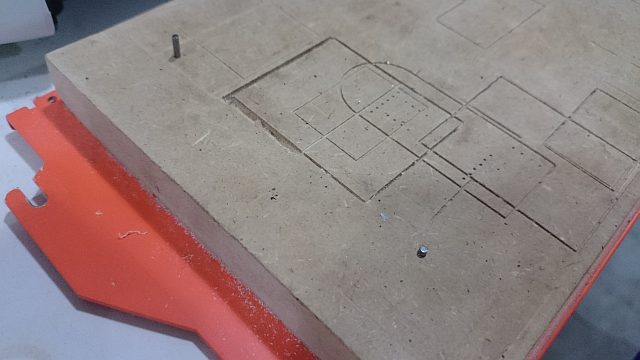
take off the board, clean it from any tape left overs and put the pins into place.
the doublesided tape on the bottom holds the board in place and keeps it flat on the bed. the pins define its position. since the drawing for the bottom is mirrored, later when flipping the board the bottom cut will correspond with the top.
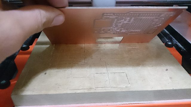
when the first side is cut you have to flip the board. first the tape needs to be cleaned off from the bottom and new tape needs to be applied to the other side. now you can put the board into its new position but remember to flip it over the same axis as the drawing!!! now mill the traces and then the cutout.
UPDATE: after flipping the board it's better to drill the holes first and then mill the traces and then cut out the board. this way it is possible to check if the holes actually correspond with the other side (see following picture).
welllllll.....
after a long time milling the holes didn't overlap! which didn't make sense until i got back to the photoshop document and found out that the image was bigger than the canvas. so i had to do it again because basically the pcb was destroyed. also some of the vias were too small in the rawing so they were not cut! in the second try i simply changed the drawing in photoschop making the dots for the vias the same sice as the rest.
hands on hardware
it's more than time to start building the mechanical side of the "tipping point"! first i built the container itself to hold all the other pieces in place.
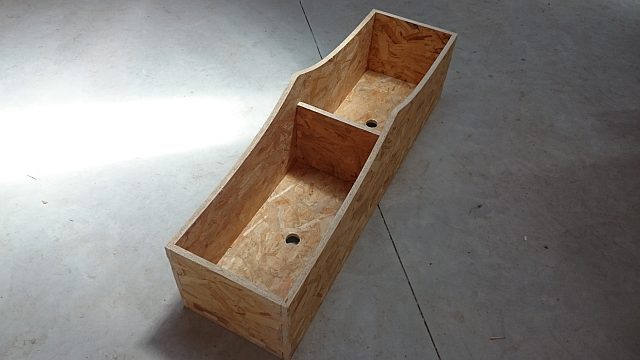
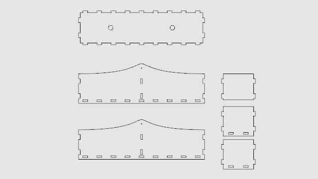
i derived the outlines of the container from the 3D model and added a simple pressfit connection.
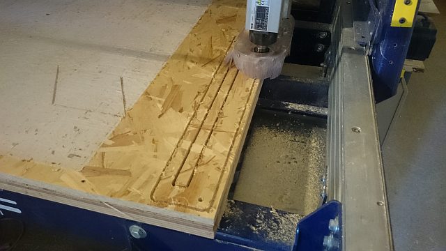
cutting the rail
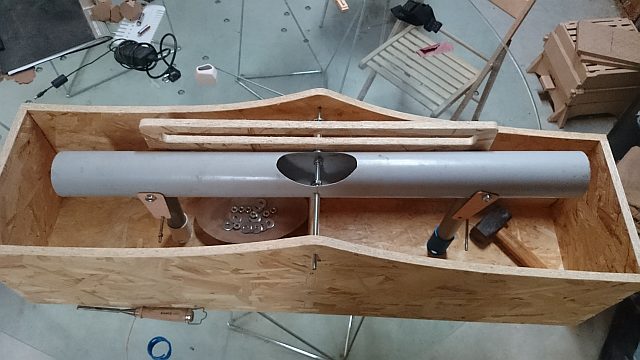
after that i started to assamble all the parts, discovering a few things which i could simplify, for example using spacers rather than nuts in various places. in the realm of spiral development i will change that in the next iteration of the project since i want to keep working on it after fabacademy.
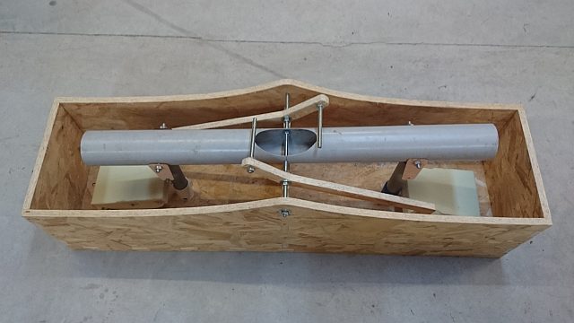
because the rail didn't work because the inclination was not steap enough to make the weight roll over to the other side and also the foam attached directly to the shutter pipes would be physically impossible to switch i had to find a different solution. instead of the rail i made two arms with a short and a long end with the foam attache to the long end. when the foam floats up the rod attached to the short end will push the seesaw down. tennis balls inside the seesaw will roll over and make it switch.
first i made the container waterproof with a layer of plastic film. around the valve it neede to be glued.
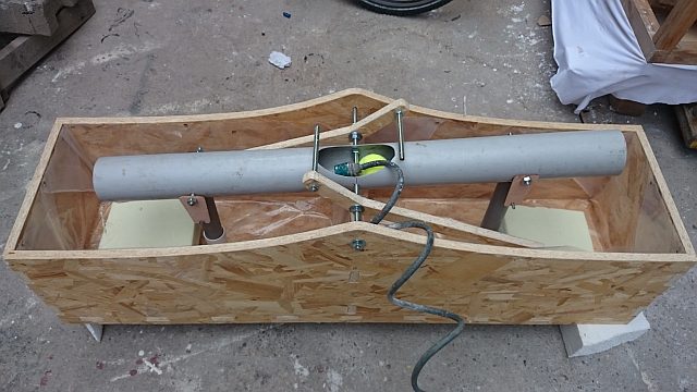
then, instead of the rolling weight, i put two tennis balls filled with sand to change the equilibrium. in order to make them roll, the seesaw pipe needs a minimum inclination. if though the hinges are directly connected to the shutter pipes, it is physically impossible to make this happen. so instead of just having holes, i extended them to slits. in that case the seesaw would switch sides when the container is filling up, as soon as the balls rollover, the hinges are being finally pulled and open the valve.
i tested and tweaked the mechanics in the backyard of the lab until it worked, and it does.
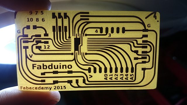
electronics news
for running the data tracker i made a fabduino, using the tutorials of
Anna and
Luciano. milling took a long time because i had to use the 0.25mm bit and clear the whole board (makes soldering easier and looks better). the first try had some troubles, for example traces that were too thin. for the second go i redesigned everything in
eagle and added text where possible to reduce the milling offsets and to later know where the pins are. i also made the traces as thick as possible to make them more stable.
the rest of the design is just for aesthetic reasons.
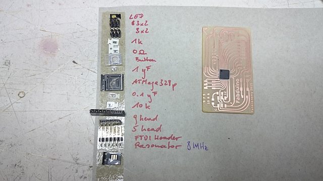
the parts used.
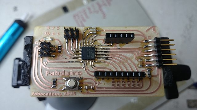
soldering done! the traces towards the processor are tiny, so i used "flux" which made the whole story a lot easier.
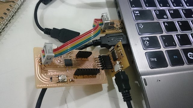
i made my own ftdi-board and tryed to burn the bootloader in the arduino ide but it didn't work. so i used a comercial ftdi cable and it worked without any problems. if i find the time i need to go into debugging the ftdi board.
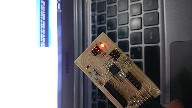
to test the the board i used the "blink" example code from the arduino ide, changing the code a couple of times and it works absolutely smoothly!
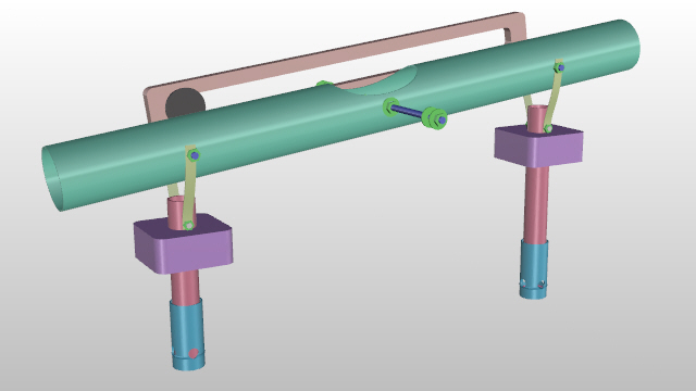
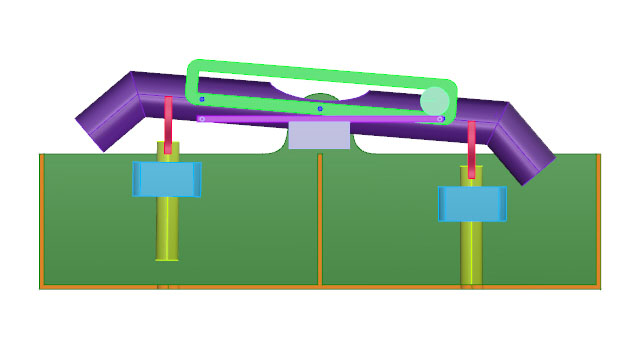
final design updated
i worked more on the design of the mechanics of the final project. now it is more detailed and gave me some feedback for the dimensions and location of the different parts. in the picture below you see only the mechanics, without the containers.
all axis will be made of 10mm threaded rodwith nuts and washers
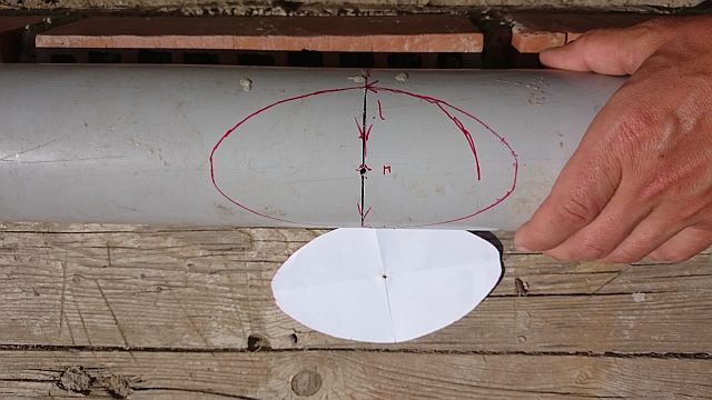
the seesaw in the making
an old pipe from the reconstruction of the house that i found in the trash will be the seesaw. i started to give it its final shape but without using digital tools, sometimes it's good to remember the manual skills...
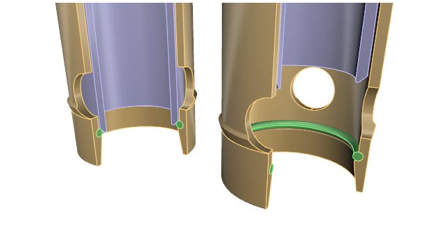
a new valve
the prototype of the valve had a couple of issues, such as being too big for the shutter pipe i will finally use. but also too short to give the pipe a certain guidance.
in the old design the ring would have easily slipped out of the fissure so now there's a gap that will make that impossible.
week_05
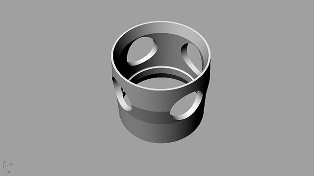
3D printing
For the bottom of the containers a valve is needed. In the molding and casting week i want to make a silicon ring to put it into the valve to seal the container with the shutter-pipe. When the shutter-pipe with a champhered end pushes against the silicon ring sitting in the fissure on the inside of the valve, below the perforation, the container will be sealed.
week_02
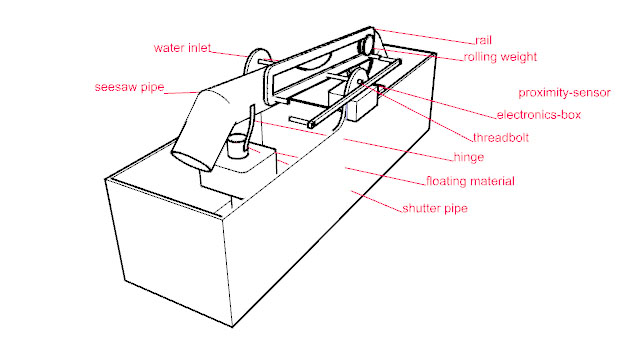
3D model
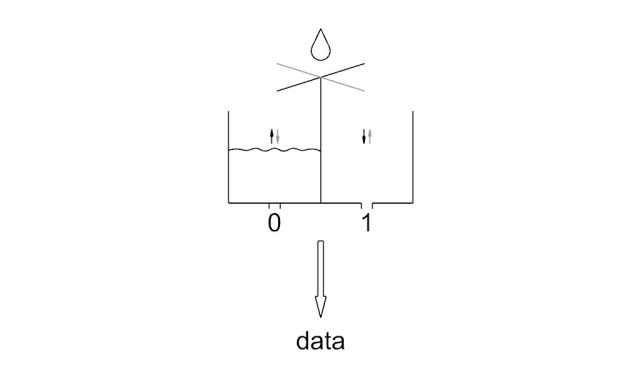
The idea is to create a mechanical tool that opens and closes two containers alternately. This will make using a turbine as a generator possible even if there is only a little amount of flowing water. By attaching a floating material to the shutter-pipe, the seesaw-pipe will be pushed up by the rising waterlevel. At the critical point a rolling weight will make sure the other shutter-pipe will be closed properly.
With proximity-sensors it will be possible to count the openings and by multiplying the count with the maximum amount of water in the containers is will be possible to track the waterflow all over the year.
In very remote areas or areas with no possibility to transmit the recorded date, it should be possible to store the data on a sd-card or something similar. Crossreferences with other meteriological data and environmental monitoring (for example an adapted version of the Smart Citizen Kit) would probably reveal interesting connections.
week_01
Status
The Green FabLab Valldaura,
in the outskirts of Barcelona, is surrounded by a network of terraces and basins dating back to the 19th century which were constructed to collect, channel and finally distribute water for agricultural production.
Unfortunately the system has not been well maintained over the last decades, therefor it is not possible to take advantage of the potential it offers. To start with, it would be essential to know where there is water leaking in the system and how much.
Mapping the inclination of the channels is a different project in a later stage.

First Ideas
- a device to meassure and track the flow of water in remote areas
- with a seesaw, two containers will be filled and emptied alternately, the moves will be counted an multiplied with the capacity of the container
- the mechanical movement will be turned into electricity to power the data-transmition and/or an environmental monitoring device