
|

|

|

|
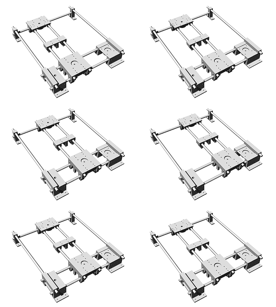
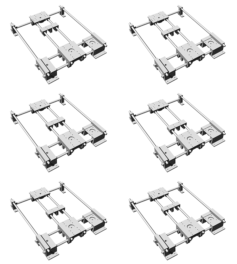
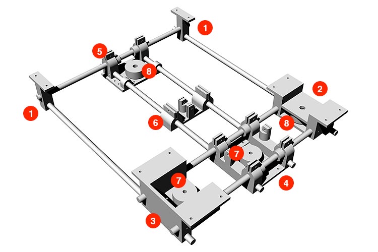
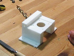
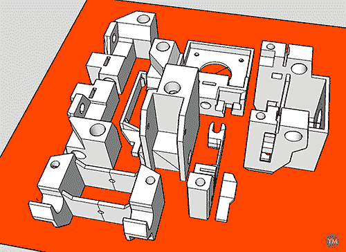
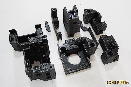
| #1 | |

|
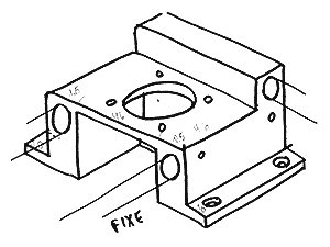
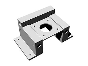
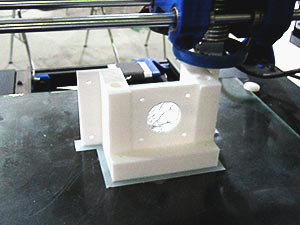
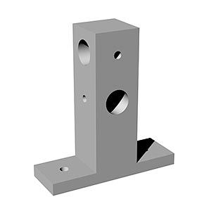
first iteration — Just designed, not printed. — Two different pieces. |
|
second iteration — Simpler piece to save print material. — Same piece for both corners. (future iterations) — Adjust diameter of the hole for shafts. |
| #2 | |
|
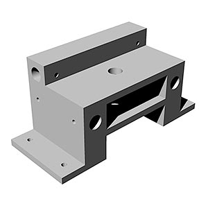
first iteration (future iterations) — Adjust diameter of the hole for shafts. — Remove the "shelf" in between the piece, making the access to the pulley and the bearing easier. — Add holes for the endstop. — Reduce the length of the hole for the vertical shaft and change the position of the hole for the screw that blocks the shaft, for easier access. |
| #3 | |
|
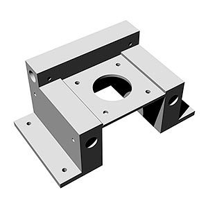
first iteration (future iterations) — Adjust diameter of the hole for shafts. — Remove the wall at the back of the piece, making the access to the pulley easier. — Reduce the length of the hole for the vertical shaft and change the position of the hole for the screw that blocks the shaft, for easier access. — Increase the thickness of the base where the stepper is placed, from 0.2 to 0.4mm, to make uniform the thickness of the base. |
| #4 | |
|
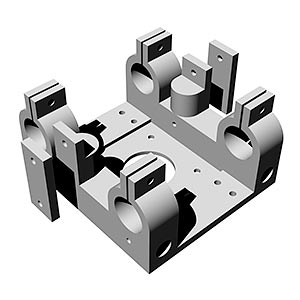
first iteration |
|
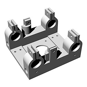
second iteration — Improvements on the clamps, more space in between and thinner walls. — Bigger hole for the linear bearings. — Re-design of the clamp that holds the belt, no separate pieces. (future iterations) — Adjust diameter of the hole for shafts. — Reduce the length of the hole for the vertical shaft. — Increase the thickness of the base where the stepper is placed, from 0.2 to 0.4mm, to make uniform the thickness of the base. |
| #5 | |
|
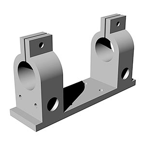
first iteration |
|
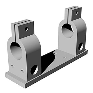
second iteration — Bigger holes for linear bearings. — Adjusting some measures. |
|
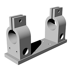
third iteration — Improvements on the clamps, more separation and thinner walls. |
|
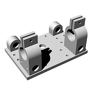
fourth iteration — Big mistake here! Missing the place where put the pulley. Bigger base. — Extra holes for the vertical shafts. (future iterations) — Add holes for the endstop. — Adjust diameter of the holes for shafts. |
| #6 | |
|
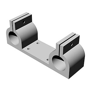
first iteration |
|
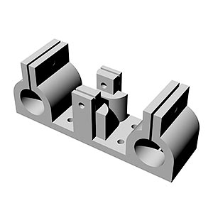
second iteration — Missing in the design how to fasten the belt! — Adjusting some measures. |
|
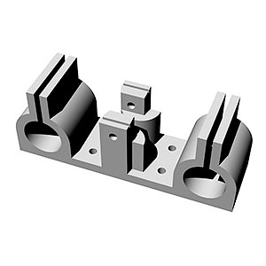
third iteration — Improvements on the clamps, more separation and thinner walls. |
| #7 — timing pulley 40 tooth | |
|
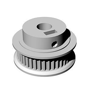
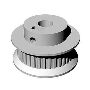
first iteration — GT2. — Sum of two designs downloaded from thingiverse and thingiverse. |

|
second iteration — Smaller hole to fit the stepper. |
|
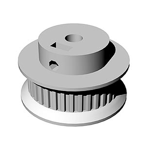
third iteration — The belt doesn't fit well with the pulley. Change to GT2,5. — Sum of two designs downloaded from thingiverse and thingiverse. |
|
fourth iteration — Smaller hole to fit the stepper. (future iterations) — There is almost no space for the screw. Adding 1mm of separation to the design will solve that. |
| #8 — idler pulley 40 tooth for bearing 608 | |
|
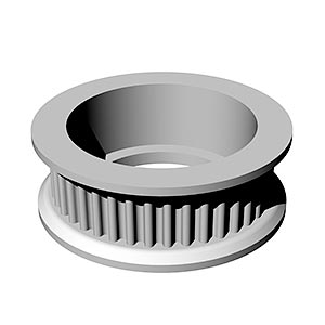
first iteration — GT2. — Design downloaded from thingiverse. |
|
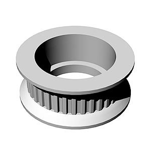
second iteration — GT2,5. — Design downloaded from thingiverse. (future iterations) — The hole for the bearing is too small, you have to sand it a lot to make it fit inside. Make the hole bigger in the design. |
|
|
|
|
|
|
|
|
|
|
|
|
|
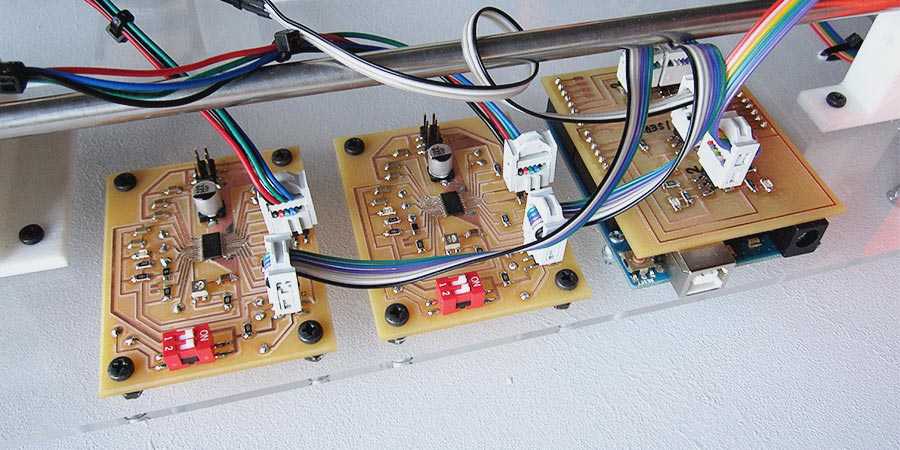
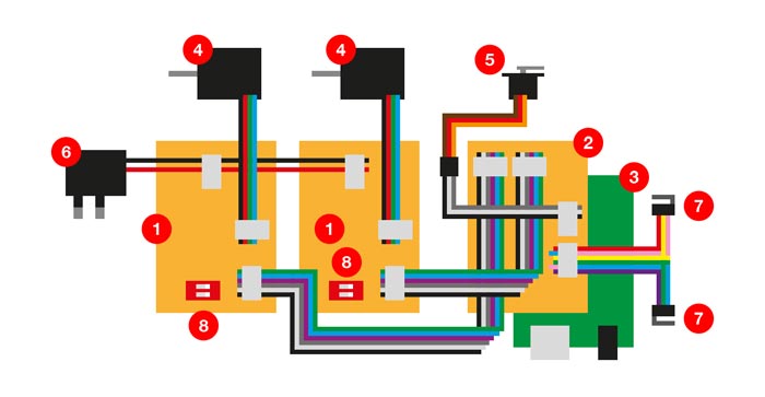
#1 stepper driver board #2 arduino shield #3 arduino UNO #4 stepper motor #5 servo motor #6 external power supply #7 endstop #8 switch to control resolution stepper (05) 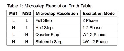
|
| first iteration | png traces | mill | front | detail |
|
(not working) |
|
|
|
|
|
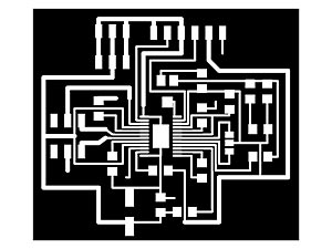
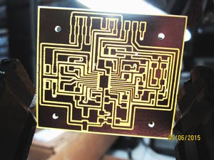
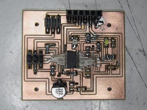
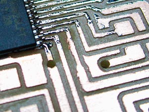
— Learning and understanding the datasheet of the A4982 driver. — Sum of various stepper driver boards that I found on the internet, working with the A4982, looking for common components (microduino, jaredwolff, melzi and codlink). — It doesn't work. I found a couple of short circuits that I fix but it still not working. — I miss the border of the vias, making difficult the soldering (detail). |
| second iteration | png traces | mill | detail |
|
(not working) |
|
|
|
|
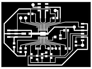
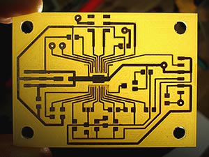
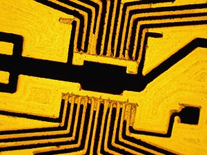
— More space between traces and milling the leftover of copper to help troubleshooting. — Bigger fixing holes. — Vias border correction. — Milling too deep, breaking traces near the driver, making it too difficult to repair (detail). — New references for the re-design of the board: fabinabox and the Gestalt board (I didn't know in the first iteration that Gestalt board uses the same driver!). 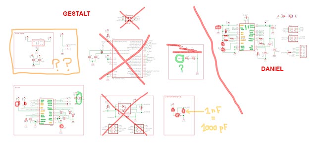
|
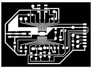
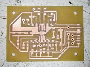
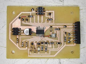
| third iteration | png traces | mill | front | back |
|
(working) |
|
|
|
|
| holes | detail1 | detail2 | ||
|
|
|
|
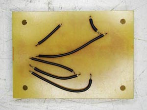
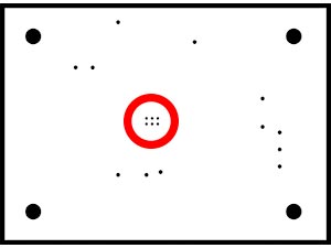
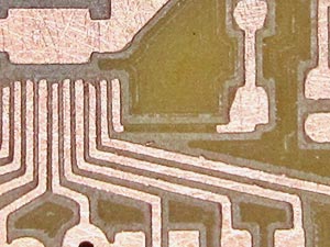
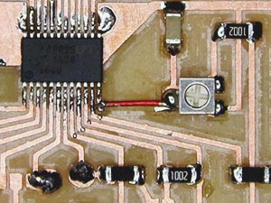
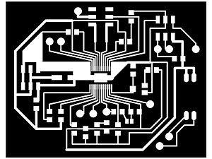
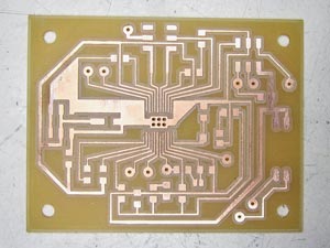
— Because I have to repeat the milling of the PCB board, and also because I have to wait till next day to use the Roland, I decide to improve the design during that night. — Adding MS1 and MS2 to the pinout. — SMD solder jumper between RESET and SLEEP. — Final tuning on the dimensions of the holes for fixing the board to a surface. — Adding holes under the driver for better heat dissipation (but because the holes are too small in the design, fabmodules don't process them well). — I brake two traces sanding/cleaning the board after the milling (detail1), that I repair using wire (detail2). — You can see the driver working at the video in the end of the page (04). |
| fourth iteration | png traces | mill | front | back |
|
(working) |
|
|
|
|
|
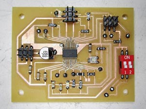
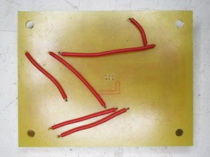
— MS1 and MS2 controlled with a switch, to avoid using unnecessary pins. SMD solder jumper between them, removed. — Layout changes, thinking on how the boards will be fixed on the machine and how the wires will be connected between them. — All the connectors the same, for easier and safer connections. — Diameter of the holes under the driver, changed to the same as vias. — You can see the driver working at the video in the end of the page. There is also a demo for the switch that controls the resolution of the steppers (05). 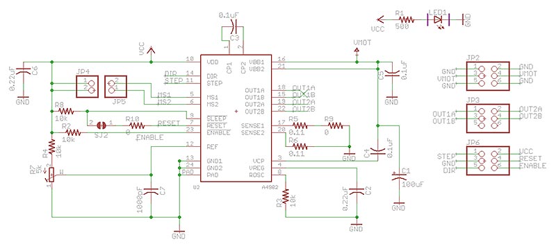
|
| future iterations |
— The SMD solder jumper between RESET and SLEEP, is it necessary? — Find an smaller switch for MS1 and MS2 (SMD size). — The notation on the switch is not corresponding with MS1 and MS2. — Try to reduce the size of the board. |
| first iteration | png traces | mill | front | detail |
|
(working) |
|
|
|
|
|
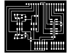
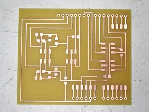
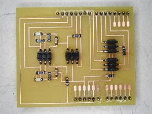
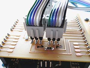
— Connections hub: 2 stepper drivers, 2 endstops, light sensor and 1 servo. — The endstops have a little circuit with leds to see when they are activated or not. — The female headers to access to the free pins in the Arduino are not soldered. — The headers for the connections of the stepper drivers are too much close each other that I need to sand the connector to plug both at the same time (detail). — See the fabrication of the shield on the video (06). 
|
| future iterations | — Separate the headers for the connections of the stepper drivers. |
