Assignment: add a sensor and an output device to a microcontroller board you've designed, read it and program it to do something
Two assignments in one. This was my approach in order to save some time (I am delayed with my assignments) and to produce a more interesting piece. At the end, I didn't save time, but I produced two in/out boards instead of one. As many previous weeks, I learnt and enjoyed a lot.
The first idea was to produce something related with my final project, something that I could reuse or something that make me learn towards the knowledge and skills that I need to do it. Because the final project, at that point, doesn't have sensors, I started thinking in parallel ideas instead of trying to change the project itself. After some ideas, I decided to work with a light resistor as an input and a servo as an output.
What I would like to do is little sculpture that prohibit to an iPhone go to sleep, detecting when the screen reduces its brightness just before it turns off the screen and blocks the phone, and then, simulate a touch event on the screen with a servo that moves a stylus.
Below, one of the main references for my final project, and also a complimentary specific reference for this assignment.
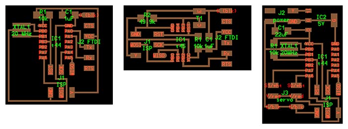
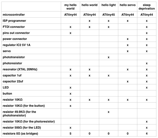
I started by listing the components from all the boards to understand which ones I will need to use in order to create the first schematic in Eagle. There are components repeated in each board that you only need to use once, but there are others that you cannot omit.
Because I didn't want to use the light sensor as a surface mount component, I need to check how the sensor that I would like to use, works. The difference was that the one from Neil's board is a phototransistor and the one that I want to use is a photoresistor, so I learnt more about resistors, transistors and diodes (because there are also photodiodes) to differentiate between them and check that the one that I want to use is appropriate.
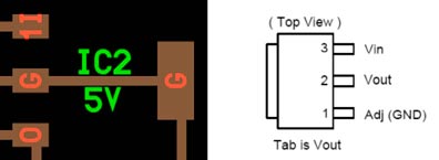
During this process I discovered that the regulator in the fab inventoryis not the same as Neil used in the hello servo board and it has different pins. Here you can see the comparison between both, the first image is from Neil's schematic, the second one is from the regulators' datasheet from the fab inventory. Related with this discovery, the fab library for Eagle contains the first one, not the one that we have in the Fab Lab.
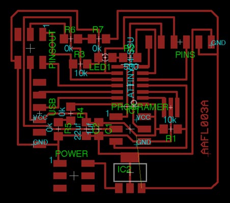
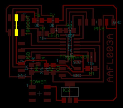
Design in Eagle. So far so good.
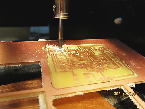
Time to mill the board using the Roland MDX-20, the available machine at that moment. Everything fine at milling the traces. I tried for the first time to "clean" the PCB by removing all the excess copper, setting the offsets to a big value. It takes some extra time but not a lot, and the result looks nice.
The drama enters on stage at the cutout moment. I forgot to set up the Z after changing the tool, I know, beginners' mistake. As a result, I broke the board and a little part of the end of the mill bit. In the next image you could see the disaster.
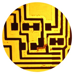
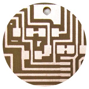
While checking in more detail the finishings of the board, I realise that there are some traces that become thinner when they pass close to a footprint, even they almost disappear in a couple of cases. I double-check the file generated in fab modules and everything is alright. I decided to repeat the board with the Roland SRM-20, and the resulting board, milled from the same file, is correct. I didn't explore more about what happened because I ran out of time that day, but we should, maybe the MDX-20 it's out of calibration (is it possible?).
Comparison side by side between the results from the Roland MDX-20 and the Roland SRM-20. This is a zoom in to see the details.
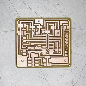
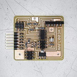
The second time that I milled the board I didn't removed the excess copper. Without and with the soldered components.
I can load the blink example using Arduino, and seems that the board works, but I cannot read the light sensor at the first attempt. To see the serial communication I need to use the SoftwareSerial library, but this is not the problem. The design of the board is wrong, I made a mess with all the VCC connections and I missed one.
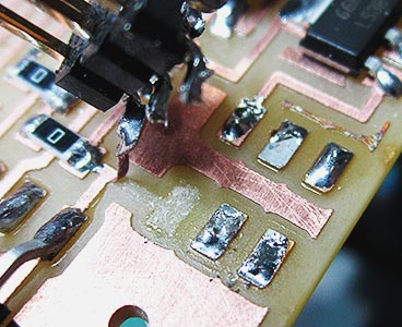
I need to fix the board, and by mistake I desoldered the wrong header and almost break a copper trace.
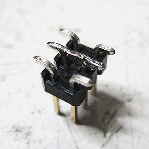
I repair it, and then remove the correct header. I just need to connect the pins of the middle in a new 2x3 header, and stuff it to the board again. Because doing this I am changing the circuit, I can not connect an external power source at the same time than FTDI to avoid overheating the regulator.
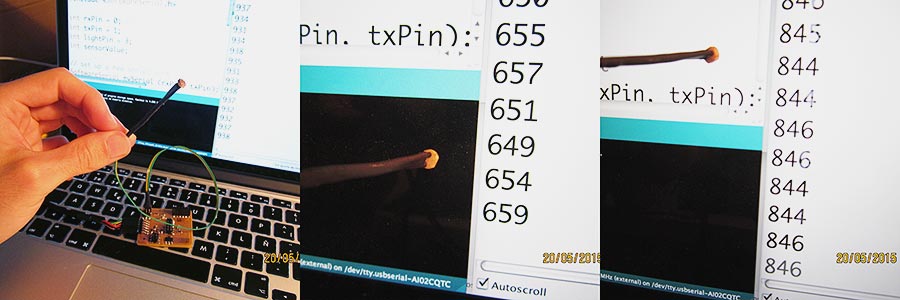
Eureka! The light sensor is working!
You can see below how the reading values from the sensor varies depending on what is pointing the sensor, a dark part of the screen or a bright part.
To finish my initial idea, I need to check that the servo works well on this board (I know, not quite a big deal), but, because right now I accumulate a lot of delay on my assignments and this time I made an extra effort doing another board which contains also inputs and outputs, I strongly think that I could stop here and start a new assignment.
Extra: game
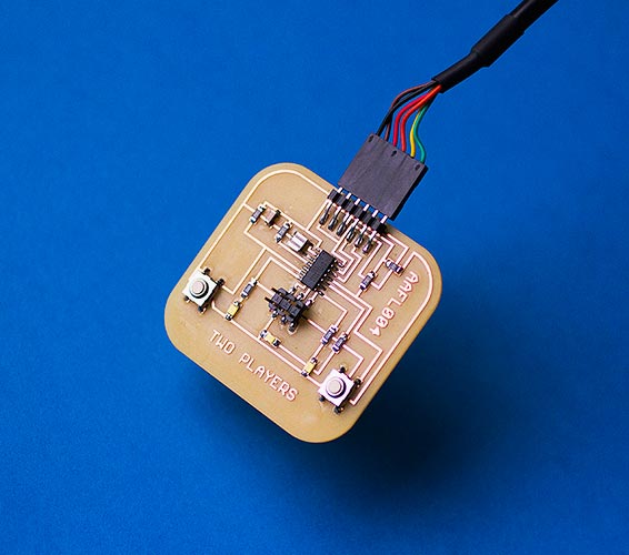
During the process of working on the assignment, I would like to do another board with simpler inputs and outputs (leds and buttons) that it's not related directly with the final project. The idea is to create a board that contains a game, similar to the old electronic games, an easy-to-understand game, with a simple interface and a "sticky" interaction. I'm talking about a prototype, nothing fancy, just the board.
The game is for two players and it has two buttons and three leds. What is the goal of the game? The first player who push the button when the led in the middle of the board turns off, wins. It's a reflex game. If a player push the button before the led turns off, that player loses. The board has an idle state between fights, waiting that the two players join the game by pushing their button at the same time.
Because this game is something that I would like to do simultaneously with the assignment, I decided to track accurately how much time I expend on that, also to see how much time I would need to create a similar prototype from scratch.
To finish the prototype, I need a total amount of 25 hours, divided into:
— game design (1h)
— board design using Eagle (4h)
— mill and solder (4h)
— code using Arduino IDE (16h)
As you can see, the programming was the part that consumed most time. This was because I had to face, mainly, two challenges.
— I had to learn how to work with millis instead of delays, in order to create events that break the flow of the game.
— The game has different states. How to manage this states, and contemplate all of them.
I had to start the code almost from scratch, three times, because my lack of plannification at the beginning. I learnt that it's important to divide code into small iterations, and build little by little.
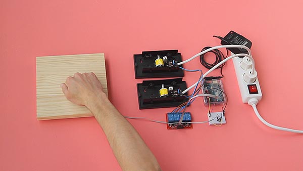
Extra extra: input/output experiment
Some days before I started this assignment, I was experimenting with Arduino, playing with relationships between an input and its direct response/translation to an output. It was a nice experience, and as it is related, I would like to share the result. Watch the video here.