Electronics Design - Check Assignment
Assignment
redraw the echo hello-world board,
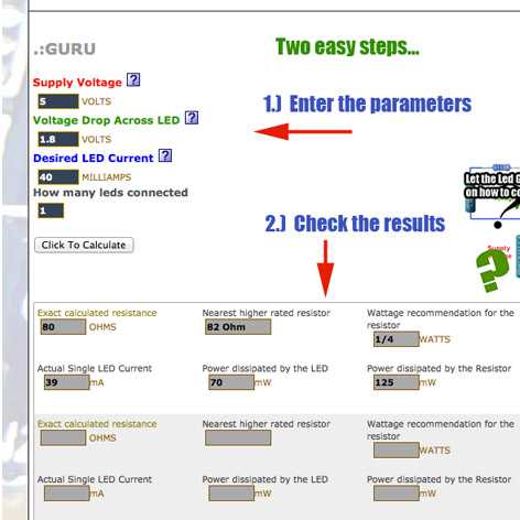
add (at least) a button and LED (with current-limiting resistor)
check the design rules, and make it
extra credit: simulate its operation
check out the assignment guidelines at academy.cba.mit.edu
Designing an electronics board is a great opportunity to really understand electronics in depth. For this assignment we used EAGLE & Gimp. You can download a free copy of both from their websites.

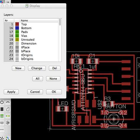
Working on EAGLE at the beginning is hard to get used to coming from a graphic designers backgroundEAGLE files
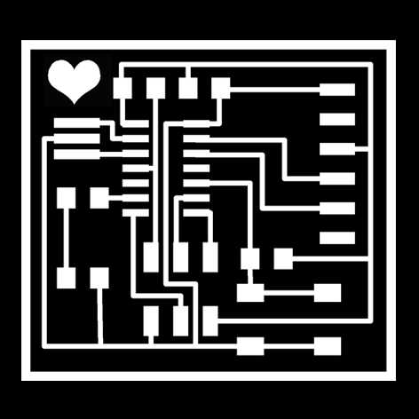
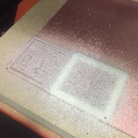
Exporting the board from EAGLE for the milling machine
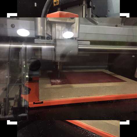
Setting up the milling machine to mill the PCB board
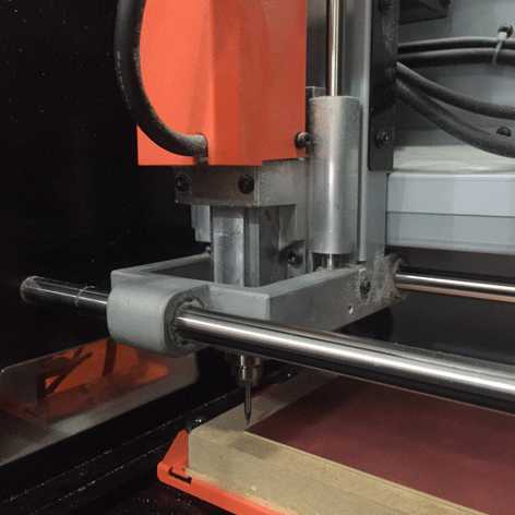
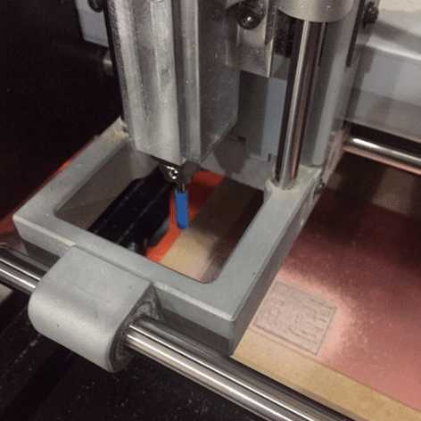
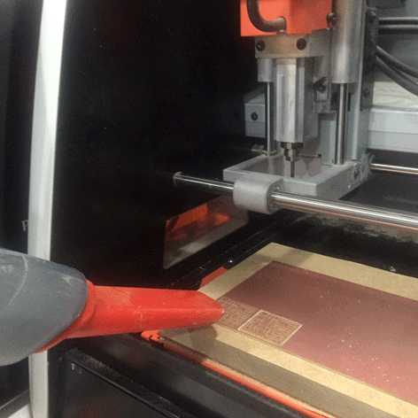
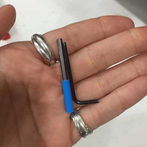
Protecting the drill bit from breaking with a cap is super important before unscrewing the piece out of the milling machine head
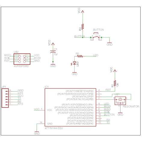
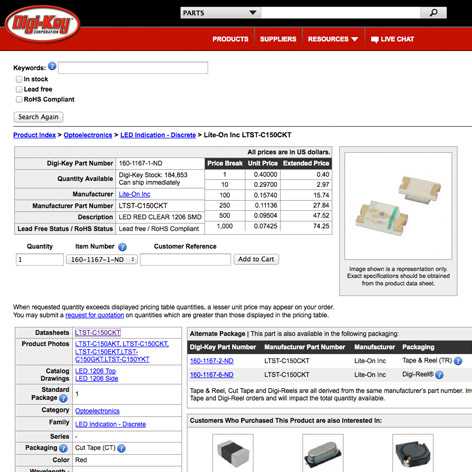
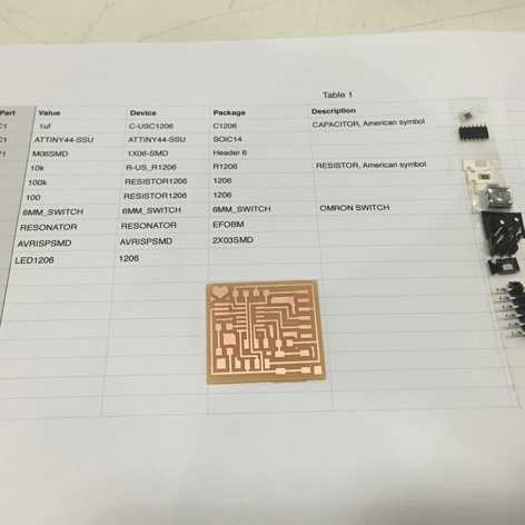
Exported the list of components from EAGLE & checking for the right components
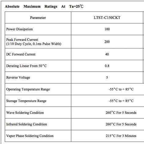
- Attiny44A: is the microcontroller;
- 6-pin programming header: for programming the board;
- FTDI header: powers the board and allows board to talk to computer;
- 20 MHz Resonator: is an external clock (the Attinty44A has a 8 MHz clock but the 20 MHz resonator is faster and more accurate;
- Capacitor: there is a 1uf capacitor, that make more clean the signal;
- 10K Resistor between the VCC and the Pin4 of the microcontroller;
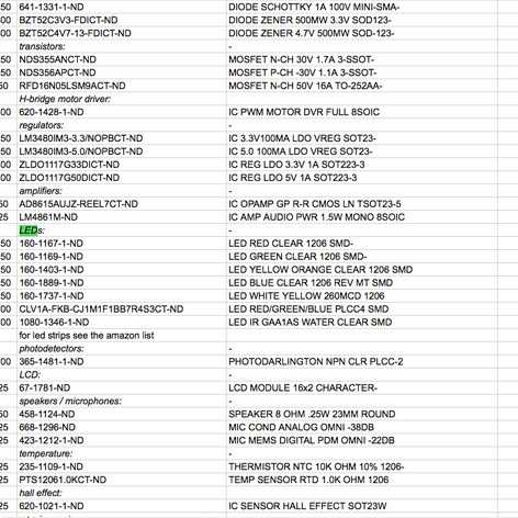
List of components, ready to solder!
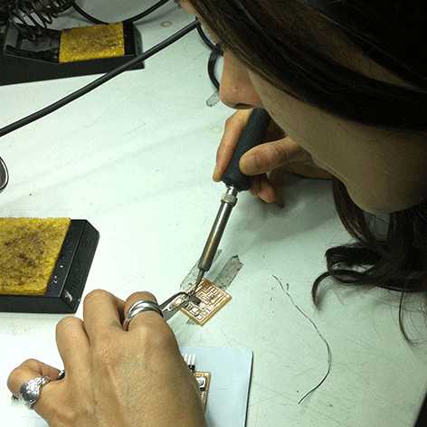
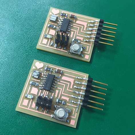
Soldering the board! Ready to program!
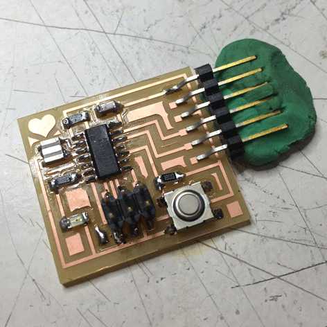

Just for practice I created two boards!