Electronics Design
This week's objective, was to re-design the "Hello_World" Board adding at least a button and a LED.
since lately I've been playing arround with the "tone" function in Arduino, i decided to attempt building a simple 4 key keyboard based on the Attiny44 chip, for making a "tiny piano".
I was limited by the number of pins that the chips provides, so I decided doing an array of buttons connected to one analog input of the chip instead of connecting each button to a different pin, i achived that, by using a series of resistors betweent the pushbuttons to decide a variety of voltages to send to to the analog Input, i also conected two outputs to headers for connecting speakers and experimenting with polyphonies or experimenting with other output devices.
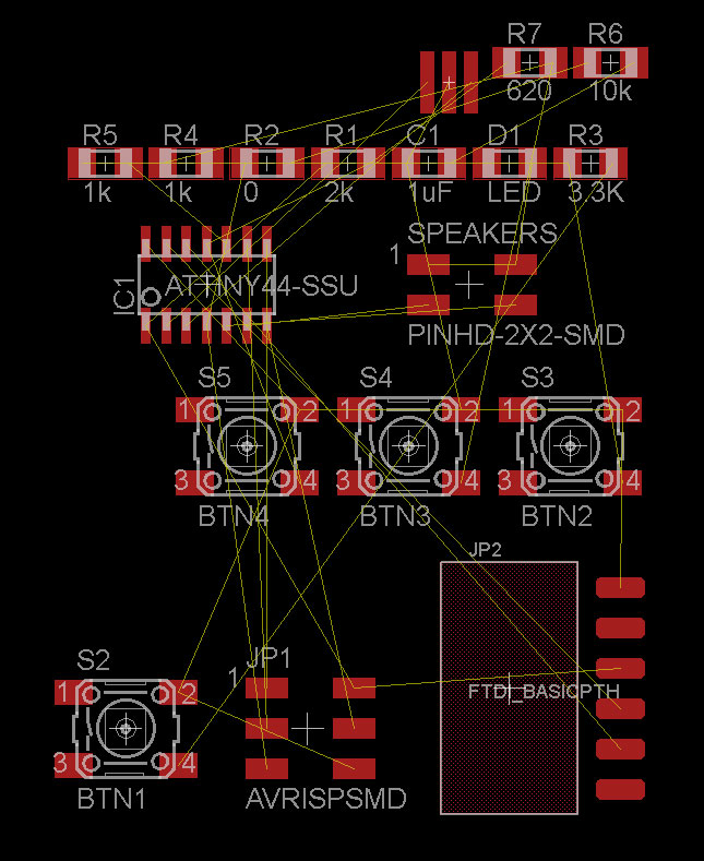
The button array inthe schematic:
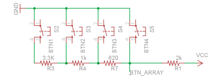
I used: 620R, 1k, 3k3, and 2k resistors, some of them are not in the official inventory, but they are realy easy to find and cheap.
I Designed the board on Cadsoft´s Eagle.

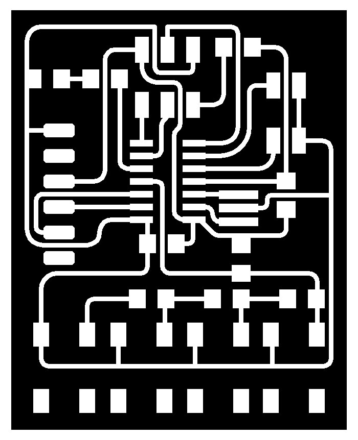
I started by drawing the schamatic, this is how it ended up:
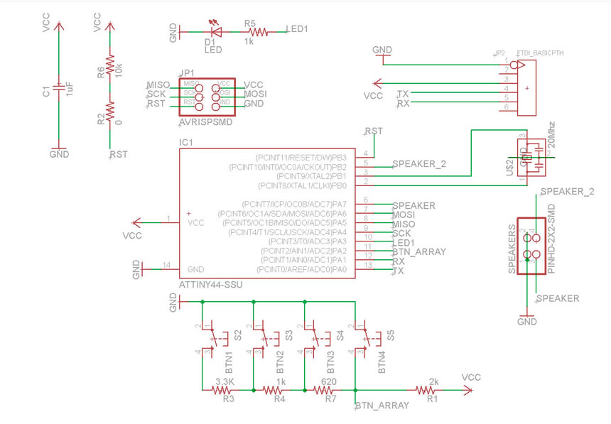
I used the fab lab's librarys from this link.
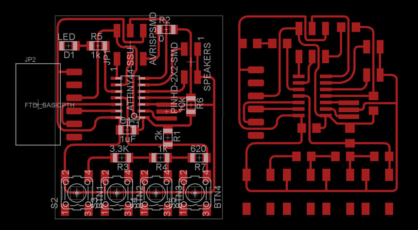
After that I went to the board's interface and i started routing the board, taking in consideration the design rules such as spacing between traces and traces thickness.
it was kind of tricky, this was the final result.
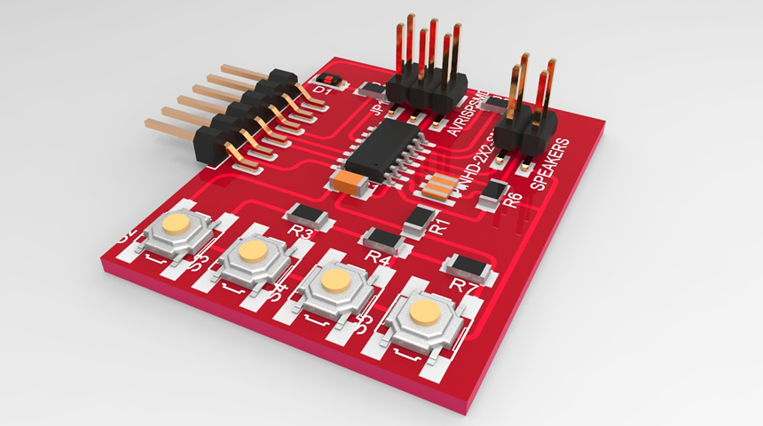
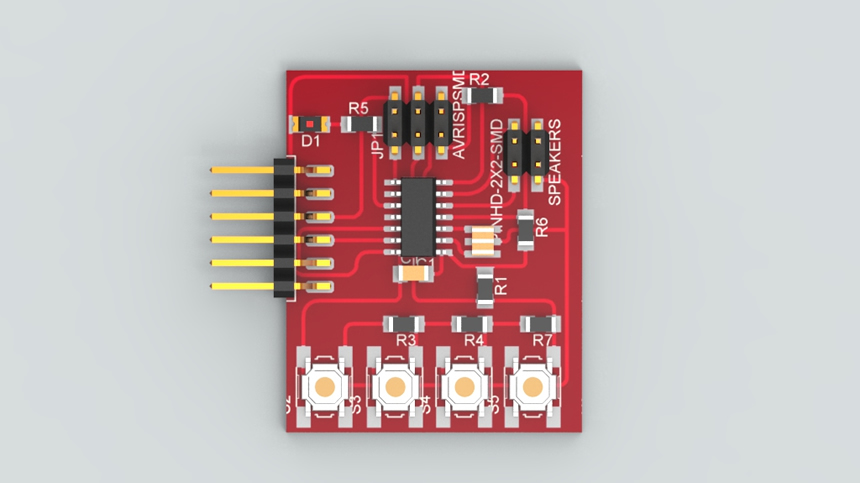
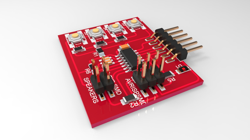
After I finished the routing I used a script for eagle called EagleUp (you can find a tutorial in this link), this script allows you to export your board to google's sketch up, so you can visualize and make a representation of your design on 3D.
This was my result:
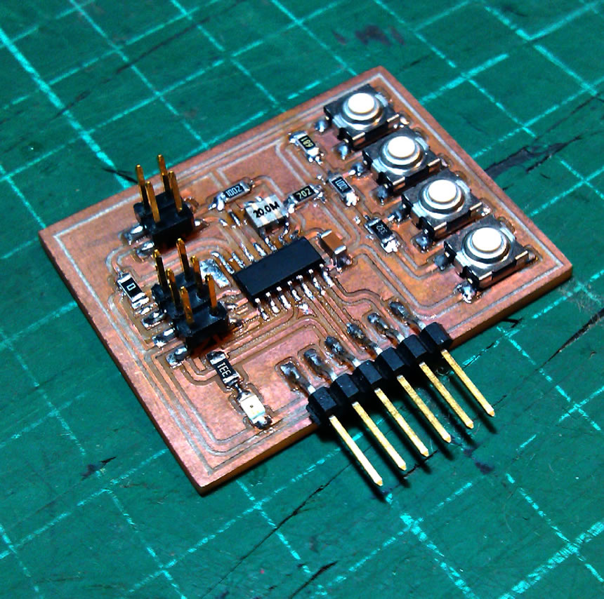
The next step was building the board. I milled the traces, cut out the border, and soldered the components in place, using what i learned on the electronic's production assignment, you can check the procedure in detail, entering on that assignment's page
After i milled the traces trying diferent parameters:
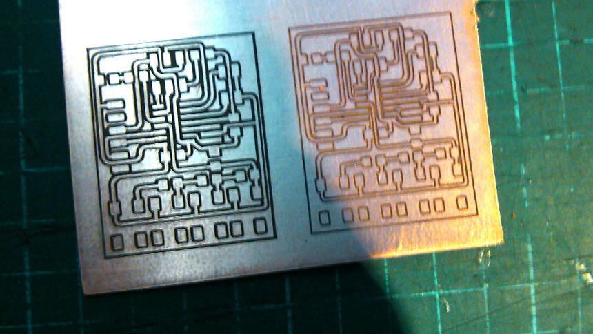
2 offsets with -0.9 on axis Z and 1offset with -0.6 on axis Z
This is the Finished board after soldering all the components, ready to be programed: