Electronics Production
PCB Milling
This week´s assigment was about of learning the technics for producing prototypes of electronic circuit boards.
The main goal of the assignment was to make the FabISP in-circuit programmer, a useful tool for future assignments, the idea was to download neil's archives, mill the board in the Modela, solder the components and finaly to program the board. I decided to take a step forward and try to make some changes on the original desing only for practicing for the future assignment of "Electronic Design" and for playing a little with the CAD software.
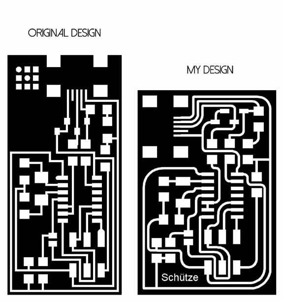
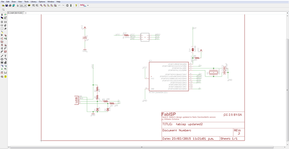
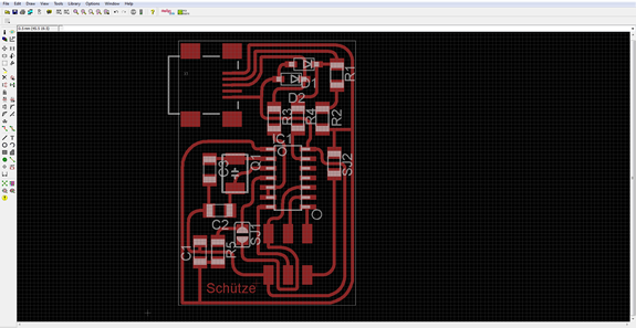
So, first i looked for neils schematic and i didn't find it, i found David A. Mellis's one, camparing both schematics i realized that they were very similar, so i updated david´s to neil´s changin some names and values an also changing the pattern of the crystal, i used CadSoft's Eagle for making the changes on the schematic and for routing the board, the routing is pretty similar to the original one the main changes are: the mini usb port is moved to the left as an effort of saving unused space on the board, the traces are curved avoiding anay chance of getting any tipe of interference on right angles, i also wanted to try the ability of the modela achiving curved traces, some other components were moved too.
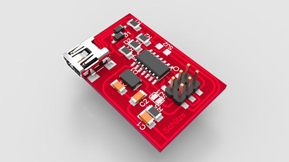
As a designer is important for me to being able to visualize the resul of anything i design (including electronics), so i followed a tutorial //here is the link// to learn how to represent my eagle design in 3D using sketch up.
Below is my resulting design.
FILES HERE
Comparing the original design to mine's
Eagle's Schematic
Eagle's Board
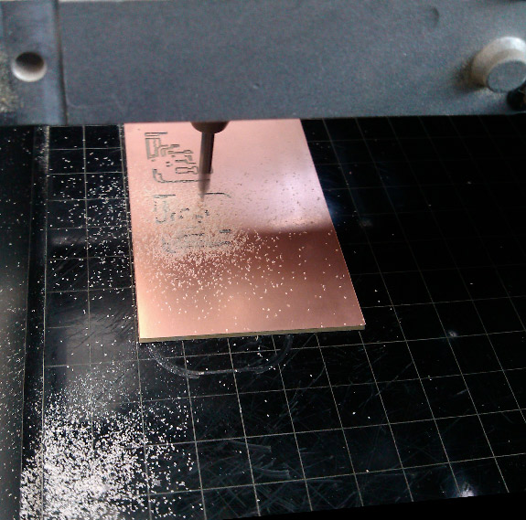
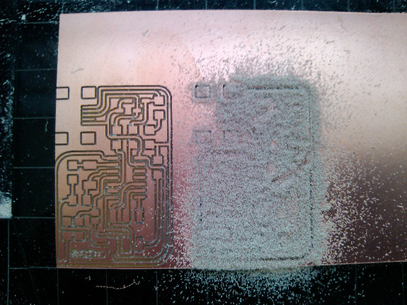
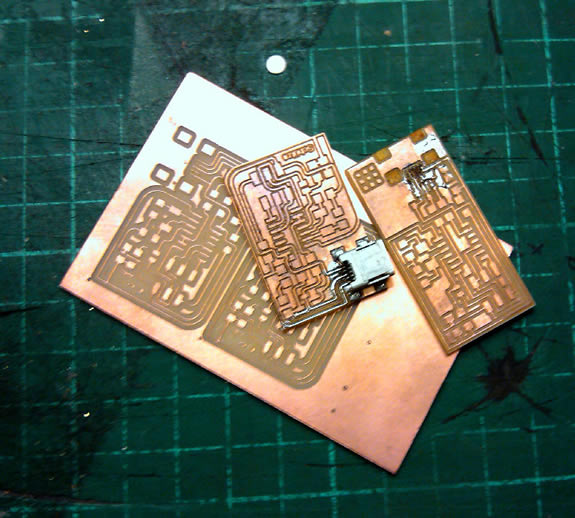
MILLING THE BOARD
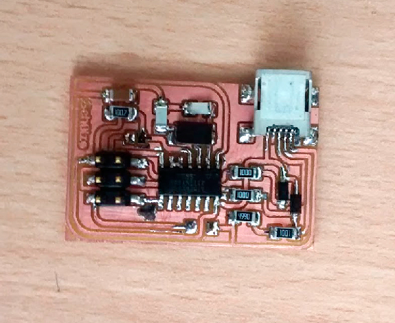
Once my design was ready, it was time to make it tangible, i used the Roland Modela MDX-20 with a 1/64 inch to mill the traces and 1/32 inch mill to cut out the contour of the board on FR1 (phenolic paper) material, I also used double contact tape for securing the material to the base.
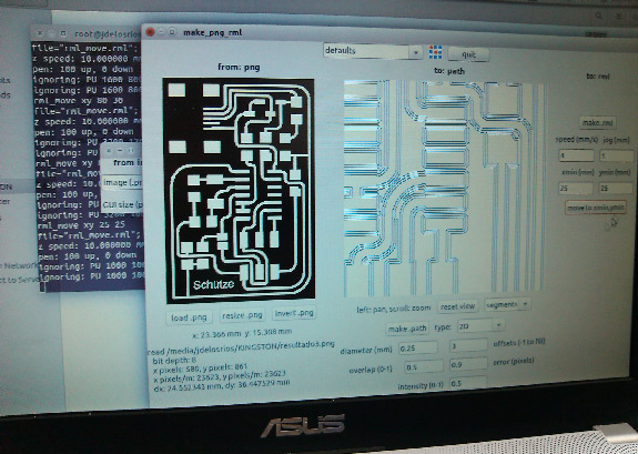
The software used was the fab modules, i tried diferent parameters, the ones that worked for me were:
Offsets: 1
Error: 0.9
Intencity: 0.5
and de Z deph: 0.1
The components:
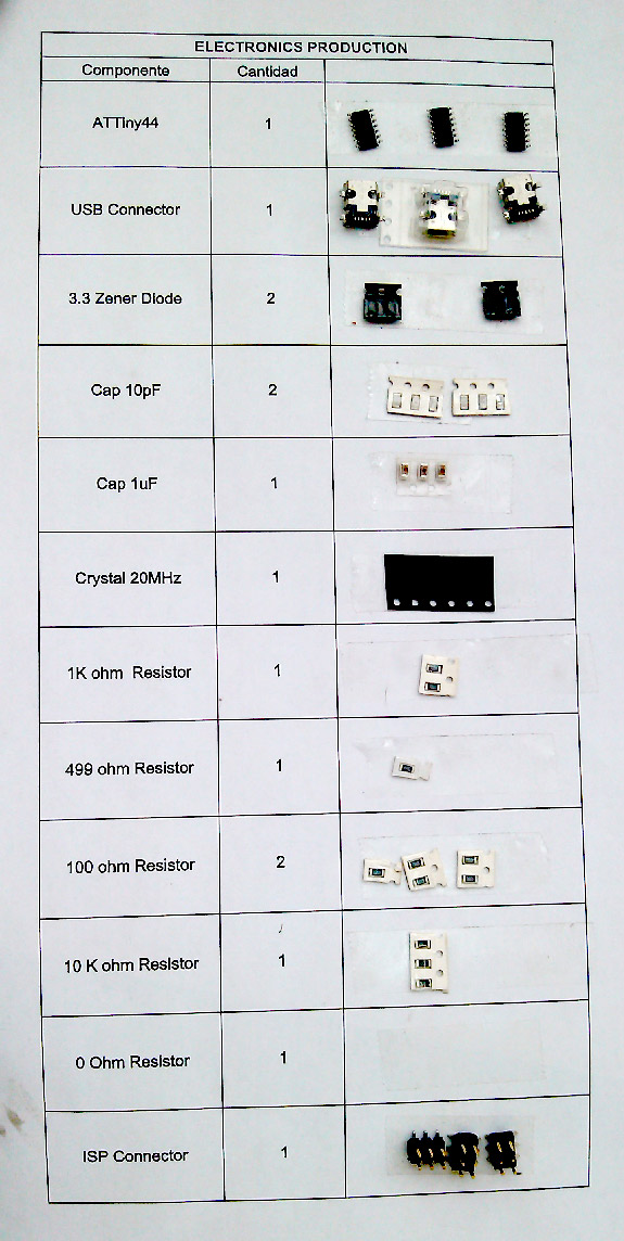 1
1
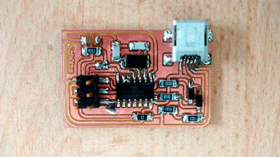
Soldering the components was harder than i thought, i failed 3 times trying to solder the mini usb connector, 2 times i broked the fixing pads of the usb and 1 time one of the samall traces.
Finally, I accomplished all the soldering, the usb connector was the hardest part for me.
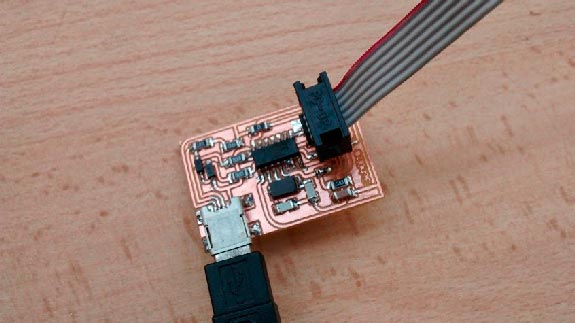
PROGRAMING THE BOARD
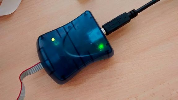
The first attempt to program the board failed but for a silly reason, i forgot to solder the jumpers SJ1 and SJ2, after i soldered them i conected the AVR programer, and all went well. Seeing the red light turning green was a nice feeling.
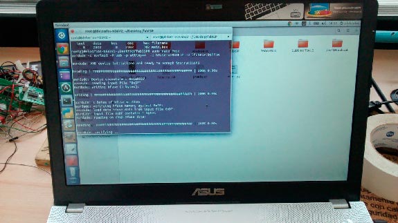
After that, I downloaded the firmware, opened the terminal and used the comands shown on the assignment web:
make clean
make hex
(sudo) make fuse
(sudo) make program
Again everything gone well.
Finally I desoldered the jumpers SJ1 and SJ2, My FabISP was ready.