COMPUTER CONTROLLED MACHINING
The activity of this week was to do something big, as the ShopBot machine is used. The steps that were developed are:
1. Design of mechanical model to assemble.
2. Parameter values in the machine software.
3. Execution of work
4. Assemble the mechanical model.
5. Pattern tests conducted in a real situation
STEP 1: MECHANICAL DESIGN MODEL TO ASSEMBLE
The first step of this activity was to think about doing "something big", so I decided to make an oriented furniture for children (because I have a young daughter so I dedicate it to her). So the idea to make my mechanical model was to create a multifunctional furniture to serve as bleachers and a small chair. To do this use design software SOLID WORKS, final assembly of my idea I show in the following figure
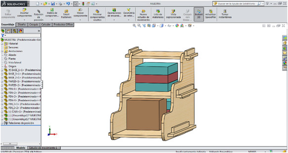
It can be observed already assembled structure, which was used only for fixing pressure base joints. Include the dimensions of the wooden board was PLYWOOD 1.2 mx 2.4 m and 15 mm thick.
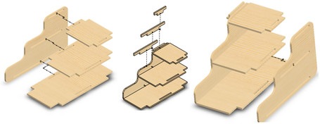
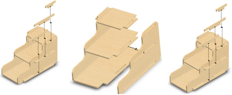
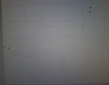
The parts and the assembly process are shown in the following image:
Finally export the drawing of the parts in a two-dimensional file, in my case use AUTOCAD to do it; and once done you export the file extension ".dxf "
STEP 2: PARAMETERIZATION OF SECURITIES IN THE SOFTWARE
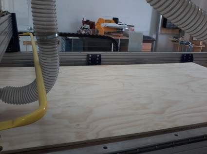
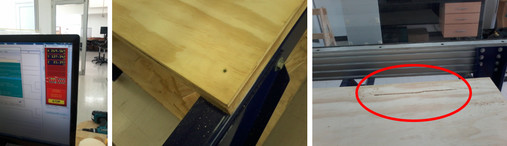
As an initial part for this part had to place the wooden board in the work area of the machine. Preferably do this with two people because of the weight of the iron.
The BOT SHOP machine has two applications in which we have to work before machining. The first is called Partworks, is something similar as a mechanic but basic software design. In her image, we want to be machined is edited. It settled mechanical parts our model, in order to optimize material.
Once the file is loaded proceed to accommodate mechanical parts to the best use. The tool to be machined is selected in this case the 1/4 inch tool was used. The tool is fixed in the mandrel
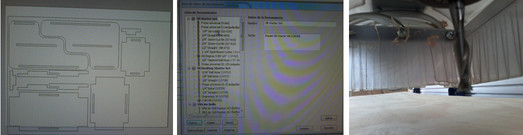
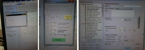
Some important parameters in the machine is parameterized as : The speed of the tool, which is based on the type of material, the thickness and the number of edges, in my case, use a speed of 12,000 RPM. Other parameters are the depth of cut, the percentage of overlap of cutting , the feed rate and the number of passes; this is because the tool can not be machined with all the depth in one pass.
PARAMETERS
Tool data: 1/4" Up-cut Bit (52-910)
Tool type: straight
Diameter: 6.35 mm
Depth of cut: 2.0 mm
Step: 5.715 mm, 90%
Screw speed: 1800 RPM
Feed rate: 80.0 mm/seg
Download speed: 100.08 mm/seg
It is also important in some small pieces presents the drawback that in the last pass of the tool, the pieces of our mechanical model can be moved by the movement of the tool. In this situation steaks, which are like small tabs that left parts of the model to remain fixed is used. At the end of these pieces cut simply break, ensuring good machining of parts. Use this for two small pieces. A surface holes were also added, these serve me to mark the points where the screws will go, this I did to fix the plate on the table of the machine. Also helped me to reduce the bow of the plate
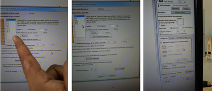
The final image of the actions shown in the following figure:
Once done you save files and movement that will make the machine are generated. The software generates two files path, one is drilling to mark the holes where the screws will go. The other file is the cutting of the pieces themselves.
STEP 3: EXECUTION OF WORK
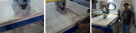
Once the above activities done proceed to execute another application of the BOT SHOP SHOP called BOT CONSOLE, I pull it previously generated files. As an initial part necessary to make adjustments calibration of the machine; ie calibrating the ZERO MACHINE.
After the first corresponding movement runs the marking of the retaining bolts in the third picture I show that due to the bow, it generated a reason in the wooden board, which did not cause me any problem in my work because in that part not had pieces.
After placing the clamp bolts , proceed to perform the cutting of other parts. It is noteworthy that the process generates a lot of noise so it is necessary to take security measures of the case, in this case the use of hearing protection
Small parts are the residue of the tabs, so we proceed to remove the excess material with a "chainsaw ".
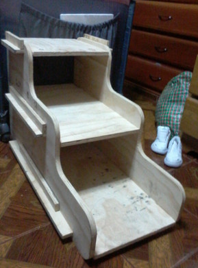
STEP 4: ASSEMBLY OF MECHANICAL MODEL
After that we can only build the assembly. But I mention I had some problems because due to the bow of wood, had problems in the assembly, so I had to lower them. The end result is the show in the image below:
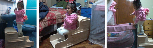
STEP 5: MODEL TESTS PERFORMED
I leave you use images that can have this furniture for children:
CONCLUSIONS:
The highlight of this activity was that I learned from small errors become larger when the mechanical model becomes larger. It should be considered in machining tolerances.
Download
- Archive 1:
Download here
