To develop the design which has been proposed in the initial part of the course, has been by convenient to first the electronic part, develop once you have this part we proceed with the design of the mechanical parts. Finally it culminates in performance tests and design adjustments that are necessary.
DESIGN OF ELECTRONICS PARTS
The table has three features:
• Reactive table option
• Illuminated chess table option
• Choice of light
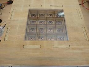
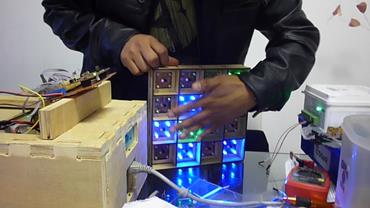
The most difficult part in this design is the reactive table option, since the other options are based on the first. An array of 8 x 8 (64 spaces) for the movement of chips is available also at a chess table. In our case, we will carry out an array of 4 x 4 (16 spaces) as the prototype for testing.
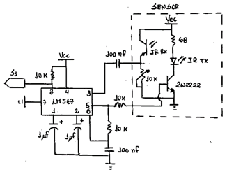
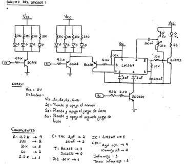
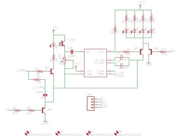
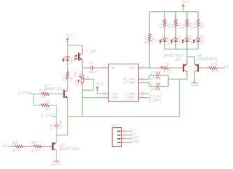
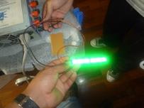
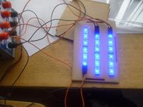
With the above mentioned, it was decided to be used as detector element to infrared sensors, and ultra-bright LED as actuator element, used. The circuit proposed for this part is shown in the following figure. In it you can see on the sensor and infrared receiver, in addition to this has been added a filter with integrated LM 567 circuit. In addition to the part of the activation of the LEDs was the circuit shown in the right part of the figure.
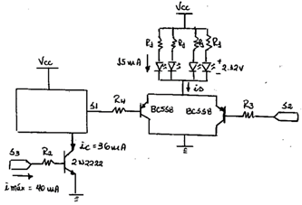
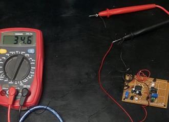
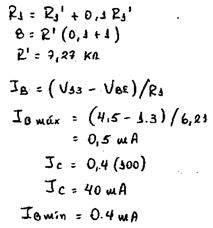
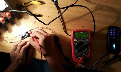
To determine the consumption of the transistor, we must verify the consumption of the entire block of detection. When the sensor is not active should be a consumption shown in the following figure:
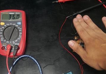
When the block is active, it has following consumption:
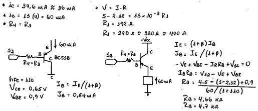
We will calculate the resistance for the case of the BC558 transistor:
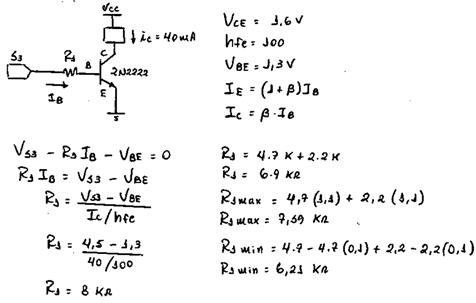
We will calculate the resistance for the case of the 2N2222 transistor:
Proving how much current will have on the base and the collector:
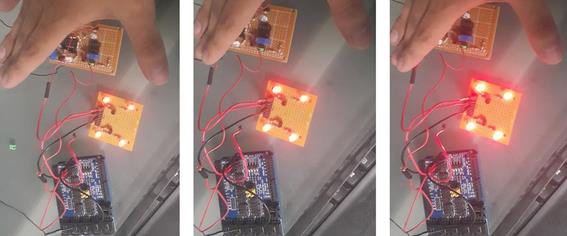
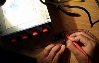
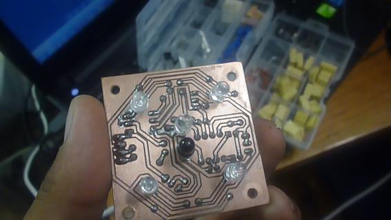
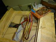
Testing the circuit to a single block of sensor, we have the following:
We first tested the circuit detects a non-reflective object:
Then verify that the leds do not work when block transistor cuts off all the operation of the:
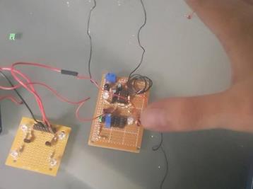
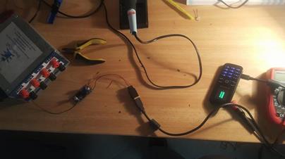
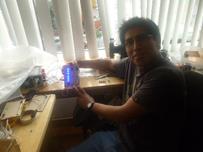
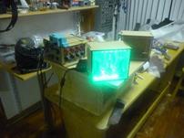
The LM2596 was tested to see if load or not a mobile phone with usb input, so begin calibrating circuit having as a source, a source of 12V computer:
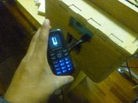
Then connect it to the phone:
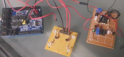
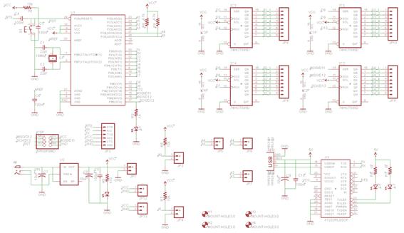
The circuits that were designed are shown below:
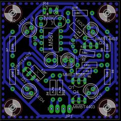
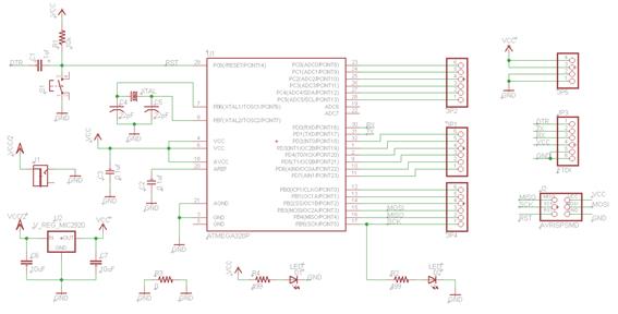
Once made the previous tests developed the schematic in the EAGLE software, it will make two versions: one using components DIP and another using SMD components. We will use the version in DIP because of availability of materials.
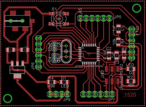
DIP IN EAGLE CARD:
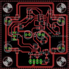
SMD IN EAGLE CARD:
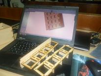
In addition to this card we will use Fabduino as our project control board.
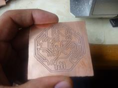
The electronic cards can be produced with designs in Eagle. A card was made for the Fabduino and 16 control cards.
The schematic end is shown in the following figure:
DESIGN OF MECHANICAL PART
This part could develop when the electronics of the project, was completed since it was necessary to have the dimensions of the electronic cards. This has made the mechanical modeling in SOLID WORKS and AUTOCAD software.
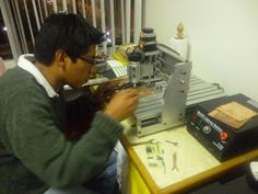
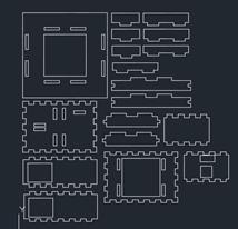
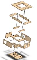
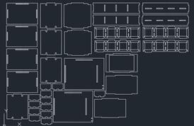
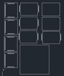
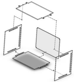
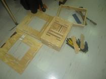
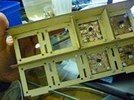
The following image shows the parts that must be machined on the SHOPBOT:
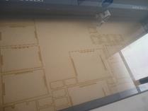
Within the design also has parts that had to be cut with the LASER cutter, the materials used were MDF and acrylic.
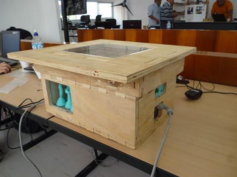
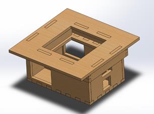
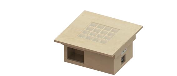
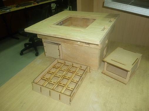
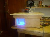
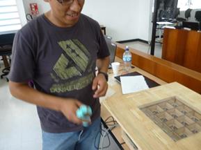
The assembled table will have the form:
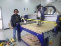
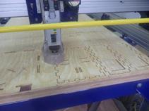
According to the plans previously shown designs, were machined them both as the SHOPBOT in the laser cutter.
>
>
Once you have the machining parts of our project, was to verify if the joints fit together. It is noteworthy that in the case of cutting laser came out correctly, in the Court in the plywood had to be a little sand joints, and that it had enough chips.
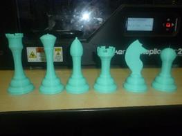
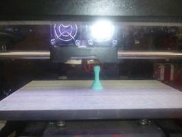
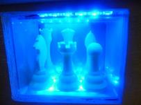
He also took in print the chess pieces.
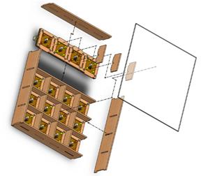
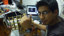
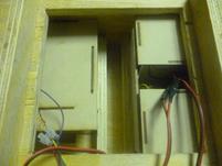
After all this was the full Assembly of the mechanical and electronic parts of the project. This process shows the following images.
>
>
>
>
>
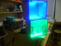
At the end of the Assembly process, the following result was obtained.
 >
>
 >
>
 >
>
 >
>
 >
>
 >
>
 >
>