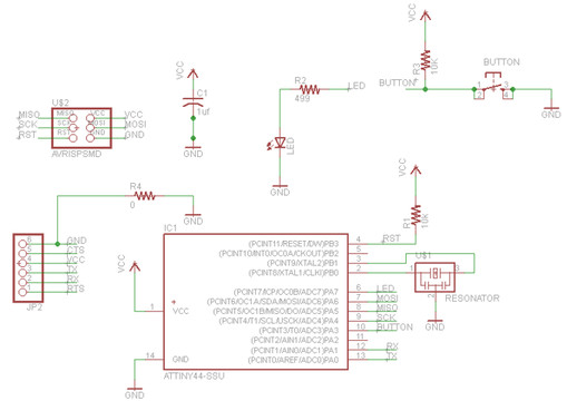
In this part of the activity Attiny mention some aspects of the controller 44. Here the most striking is to know the input and output ports and their types , ie without are analog or digital nature and activation condition thereof.
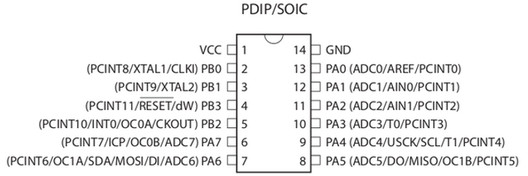
Description of the pins is as shown:
- VCC: Power supply
- GND: Ground
- RESET: Restarting the microcontroller
- PORT B (PB3-PB0): Essentially ports are bidirectional and can serve as input and output, but moreover the PB3 port has the ability to RESET which has by default and must be modified to function as input and output.
- PORT A (PA0-PA7): Essentially bidirectional (input/output), also although both B and A are bidirectional port is the port to which it is known for its analog inputs.
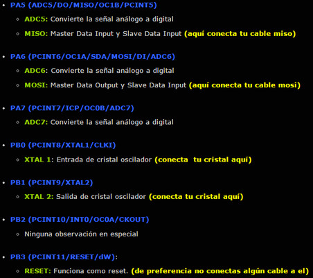
The microcontroller has alternative functions that help us to work with more easily and are detailed in the upper diagram of the microcontroller. We will highlight some for this assignment
PART 2
Activity last week, in which a circuit board containing the microcontroller to their respective components to run it was made, and he placed a sensor and an actuator. As you can see the sensor was a button and the actuator was a led with their respective current limiting resistor.
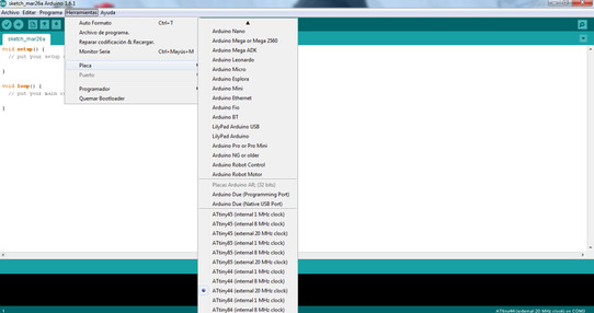
The software support for this was "Arduino IDE", which is a text editor that allows us to program the application you want to perform.
Start by installing Arduino. The program is free on the internet so the download of it is pretty easy, then you just have to locate the library. We should have something like this on the screen Arduino.
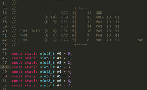
Must be regarded as the microcontroller pins , because reading makes Arduino IDE Paws Attiny is different than as shown in the schematic of the Eagle, for this equivalence table shows:
In my file of the schematic of the Eagle, which I show below, we see that the pin 10 corresponds to input and output pin 6 to the microcontroller. Therefore according to the picture above equivalence for Arduino IDE is:
PA03 = 3 (Arduino) Sensor Input
PA06 = 7 (Arduino) Departure for the LED actuator
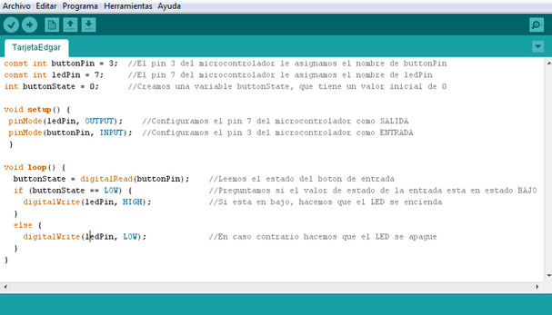
Here I show two programs in Arduino IDE, as you can notice the comments made by each program are followed by the symbol //, it can be noted that each segment makes programming .
PROGRAM 1
The first program shown in the figure, is one very basic, in which each time we press the button and the LED lights , and each time this button without pressing the LED stays off. Note that the program reads the low level because the configuration I connected my button is PULL UP (for the connection of resistance).
The basic structure of the program is divided into two parts: The first is the declaration of inputs and outputs and the second is the program itself.
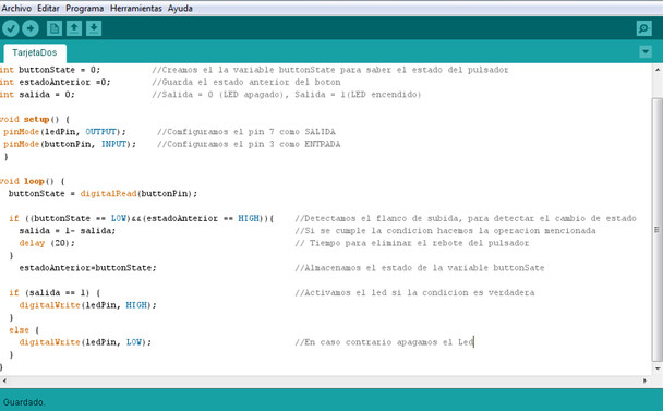
PROGRAM 2
In this second program is the first amendment, which if we press the button the led, if we press the LED turns off. As you will notice is a little more complicated than the previous one, this
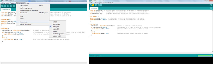
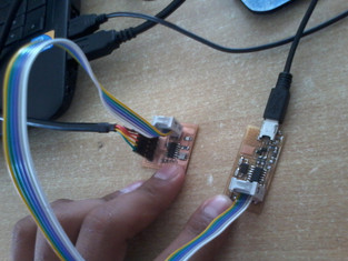
Finally program for etching performed using the programmer card previously connected with the sensor and where the actuator is done.
As a pre- recorded program step complication of it is done this in order that no errors. We make sure the recorder is the USBttiny . Then simply give you the option to download the program and ready. After this you can check the operation of the program.