The practice of this week is to modify the design of the plate "Echo Hello- World" in a suitable software and finally make it. Later in a subsequent task will be scheduled for a particular application.
The sequence of work was as follows:
1. Download and install the Eagle program.
2. Update the library in the Eagle software.
3. Download the file to the plate "Echo Hello- World".
4. Modify the file to put a sensor and a basic actuator.
5. Generate the PCB for It is noteworthy that the type of license is "FREEWARE".
6. Solder the components.
STEP 1: DOWNLOAD THE EAGLE PROGRAM IN LINUX
This part was not so difficult because I relied on the corresponding tutorial this week. Only I addressed in the tutorial , download the file and proceeded to install Linux. It is noteworthy that the type of license is "FREEWARE".
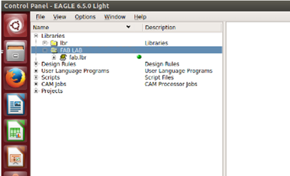
STEP 2: UPDATE LIBRARY IN EAGLE
For this part of the course links Niel, I found the library file "Fab.lbr" which is the library of components used in the "Echo Hello- World" board.
Keep the library in the default folder that is generated in Linux, for that, I made sure to keep with the correct extension. This to avoid problems with the installation of the library.
Once in the program, observe that the library had a right bank a button was gray, searching for information, meant he was not enabled; therefore, to enable it enough to give right click and selected the "use" option and the library was enabled.
Navigating the library I realized it was all components used on my plate , from the microcontroller Attiny up the buttons. By the way, were enough components available.
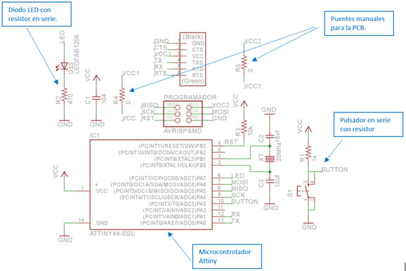
The file of the plate ( is the schematic circuit ) was given to us by our course tutors, it should be modified to the plate of our activity this week . As can be seen in the plate there are components that we do not need.
While it is true that the schematic was delivered by our tutors, the circuit is available within the course of FAB LAB.
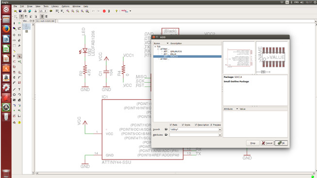
STEP 4: MODIFICATION OF CIRCUIT " HELLO WORLD -ECHO "
To perform this task, we worked with the schematic to modify, using the software and tools was able to perform this task.
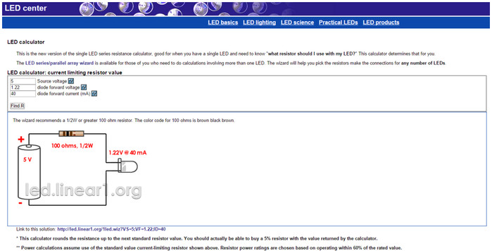
In the case of adequate strength for the LED will go as actuator Attiny driver, recommended by the tutorial called " LED Center" page, in it as shown in the window was used, place data: The power supply to the load ( resistor in series with the LED ), the threshold voltage or voltage drop in the diode current and the diode can support . With these data we are given the value of the corresponding resistor with his power.
While we went resistor 100 ohm 1/2 watt, preferred to use one more, in my case a 470 ohm resistor.
To place the components was necessary to have knowledge of the physical size of the device since the software has options of sizes and mounting type.
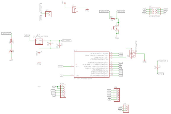
The final schematic of the proposed circuit shown in Fig. As can be seen has placed a resistor value of " zero ohms " which does not exist as a real device , we used to say they are jumpers that must have the plate. I did it this way because if it is true, the software generates Eagle bridges when making PCBs , they did what needed to be done considering the bridge by external cables. Due to this as available physical bridges available use for a better finish .
As shown in Fig I connected the input (push) to the terminal 10 of the microcontroller, the actuator is also connected to terminal 6 respectively. As you may notice this means that both the input and the output will physically connected by a track on the PCB. To maximize the benefits could be proposed separate sensors and actuators on another card, and would join by bridges to the inputs/outputs of the microcontroller.
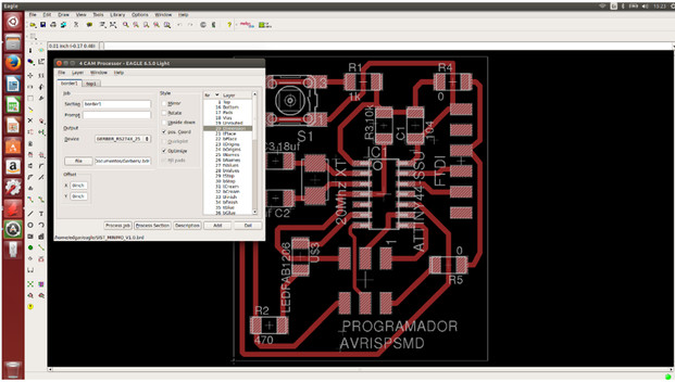
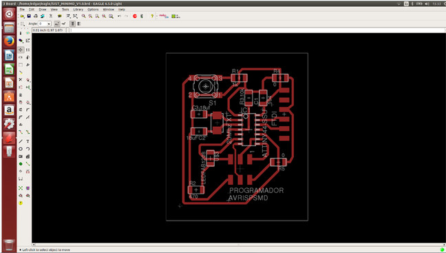
STEP 5: GENERATION PCB
The export for the GERBER file was not very complicated , and I followed a tutorial that got surfing the web , I followed the steps and got the files for machining . The Gerber files generated correspond to the "top " layer and the " contour" . The software presents the "Generate / switch board" option which allowed me to get the PCB , it is necessary to do additional work to move the components in the workspace Eagle and generate leads. To explain this better I attached a video link which I followed and I worked for my board.
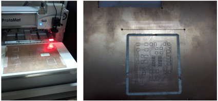
Taking the files we took him to the machine ProtoMat S63 place the necessary adjustments so that it can work. In this part as shown in the figure, when sent the PCB shown in Figure I generated an error in the final card because when making the corresponding cut to the outline did not come out very well, so much so that I damage the plate.
Then resize one greater contour and the results are shown in the figure:
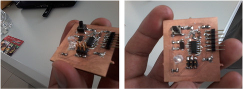
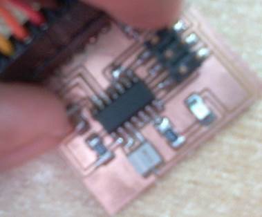
STEP 6: WELDING AND PRESENTATION CARD
The final presentation is as follows:
The card was made for the components to be superficial type, but when obtaining components , there were some ; so it was necessary to adapt DIP components and solder them properly on my plate.
CONCLUSION
It is not advisable from an aesthetic point of view mesclar components insertion mounting plates are designed for a surface mount components.
REDESIGN OF BOARD WITH SURFACE MOUNT COMPONENTS
In the next picture redesigning the card for a surface mount components.