The task this week was to model our project in different softwares. After this was due to make a comparison on which alternative was the one we liked to do it.
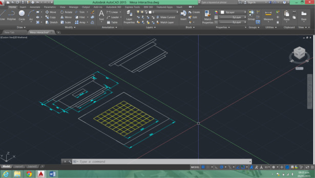
MODEL IN AUTOCAD
In this part of the drawing was conducted in two dimensional sketch of the project in two dimensions, it can be seen the approximate dimensions of our model seen in its three main views: front view, side view and top view.
MODEL IN INVENTOR
In the case of this software began developing the part of the structure that will go the LED lighting system from the table. About this framework that will sustain added.
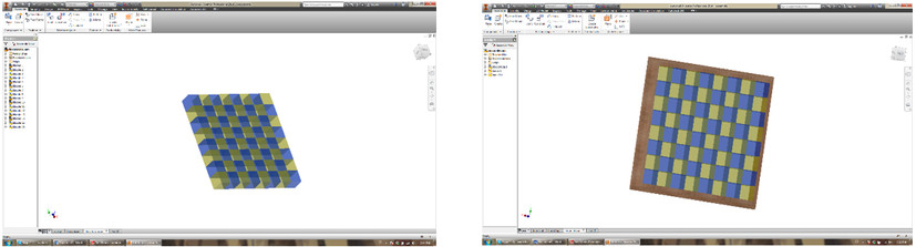
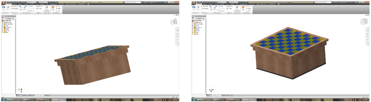
The bottom of the table is then added. Finally the final presentation made in Inventor is shown.
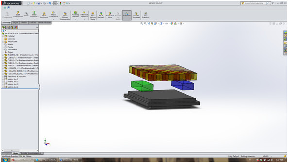
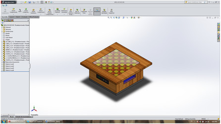
MODEL IN SOLID WORKS
In this part modeling using SOLID WORKS, for this part of the work table was drawn with most of the details that you will have made our interactive table
The working that job was to draw several parts, which are then assembled into a complete solid.
The figure shows the part of the system of LEDs lighting and shelf bra has shown.
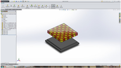
In this other image boxes where they will go all the electronics portion of the project is observed, shown as boxes of green and blue.