As you can see there are several actuators in which we can work. In my case I chose the actuator and additionally RGB LED array 20 LEDs. As you can see in the following figure, you have all the files needed for the activity: the "board" file and " components" serve us at the time of soldering the components; Files " traces" and "inner" are used for the machining of the PCB on the machine "models ", the first track circuit and the second is the cutting path. Besides files "make file" for engraving appear as the means we have available and the program "C".
STEP 2: CONSTRUCTION OF E- CARD
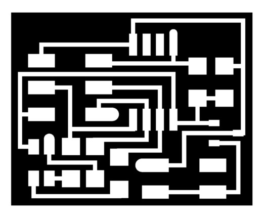
With the " traces" file is determined, the routing of the tracks on the circuit board for this we use the cutter 1/64. The procedure is the same as the activity of "INPUT DEVICES " was held.
After waiting for the machine models " end of the runway pattern, it proceeds to change the bur by 1/32 inch, once the file is loaded done " inside " and the option to change the cutting machine.
STEP 3: WELD COMPONENTS IN CARD
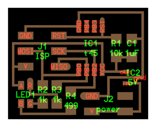
To weld the components of the card is necessary to use the file " components". It can be seen the position of the various components on the card. As can be shown in the figure, a Attiny 45 microcontroller was used.
For more information check this link ATtiny 45, where you can download the datasheet:
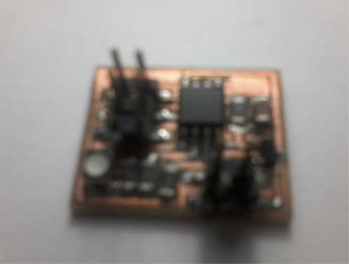
In the next picture the end result of the card with the components and soldiers shown.
STEP 4: LOADING THE PROGRAMME ATtiny 45
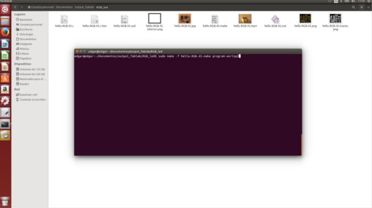
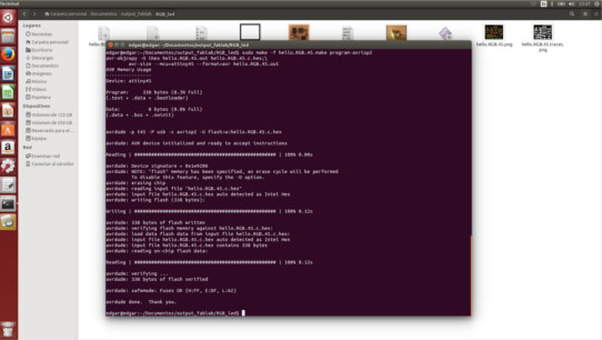
After performing the above, April is necessary "Terminal" of Linux, it must locate the folder where the files are, in this case the "RGB_led". As a preliminary step we execute the "lsusb" command to recognize the recorder. Run the command as it appears in the image; do not forget to place your key to execute.
After that a window similar to the one shown should appear. In the event that errors appear check welds cards also verify that there are no short tracks.
STEP 5: CHECKING THE OPERATION OF THE APPLICATION
Once the program is loaded and can check the operation of the card, the demonstration is shown in the following video.
VIDEO RGB ORIGINAL
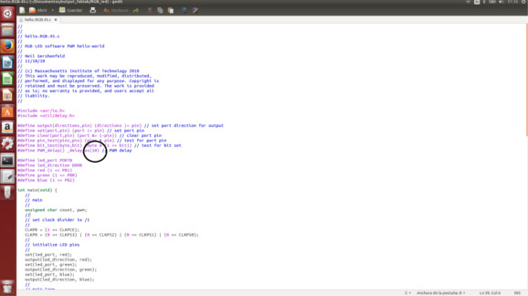
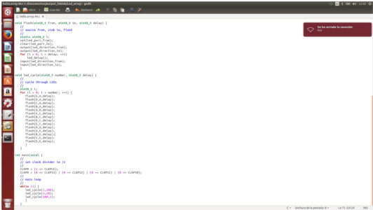
According to the " C" code is loaded, I made a modification to the RGB LED light faster. As you can see in the figure was a change in the highlighted part. The result is shown in the video below.
VIDEO RGB MODIFICADO
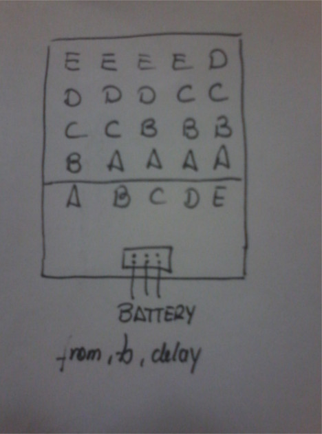
As an additional task the actuator LED array, which operation is shown in this video was built.
VIDEO MATRIZ DE LED ORIGINAL
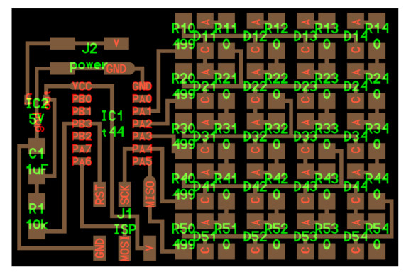
Tracking tracks the card got the diagram as shown in the picture.
Because of this I could modify the program in " C", the modification is shown in the following figure:
Video of the result of the modification shown below.