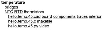
As you can see there are several sensors in which we can work. In my case I chose the temperature sensor and additionally did the magnetic sensor. As you can see in the following figure, you have all the files needed for the activity: the "board" file and "components" serve us at the time of soldering the components; Files "traces" and "inner" are used for the machining of the PCB on the machine "models ", the first track circuit and the second is the cutting path. Besides files "make file" for engraving appear as the means we have available, the file extension " .py " serves to bring information present temperature reading and display it on the screen of the PC.
STEP 2: CONSTRUCTION OF THE ELECTRONIC CARD
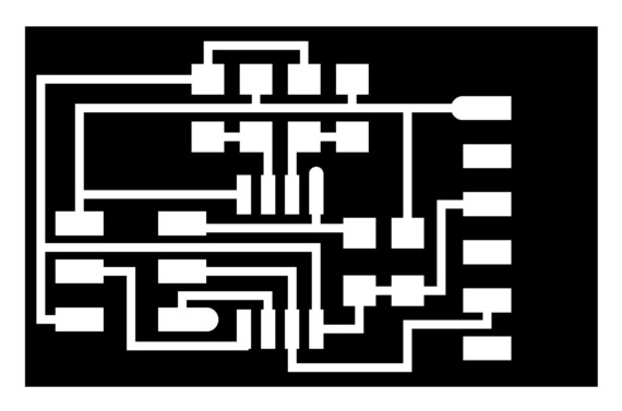
With the " traces" file is determined, the routing of the tracks on the circuit board, for this we use the cutter 1/64 inch. The procedure is the same as the activity of " electronic production " was held.
After waiting for the machine models " end of the runway pattern, it proceeds to change the cutter by 1/32 inch, once the file is loaded done " inside " and the option to change the cutting machine.
STEP 3: SOLDER THE COMPONENTS ON THE CARD
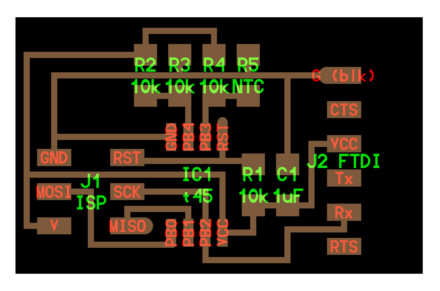
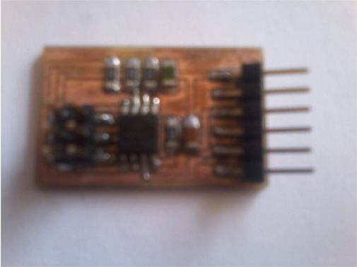
To weld the components of the card is necessary to use the file " components". It can be seen the position of the various components on the card. As can be shown in the figure, a Attiny 45 microcontroller was used.
For more information check this link ATtiny 45, where you can download the datasheet:
In the next picture the end result of the card with the components and soldiers shown.
STEP 4: DOWNLOAD THE PROGRAM IN ATTINY 45
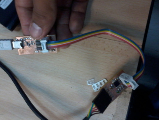
Connect to our programmer FabISP manufactured through a 6-pin connector card. It is noteworthy that must also connect the " FTDI USB " cable, it will use it as a power supply for the card.
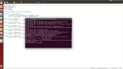
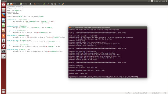
After performing the above, April is necessary "Terminal" of Linux, it must locate the folder where the files are, in this case the "TEMPERATURE". As a preliminary step we execute the " lsusb " command to recognize the recorder FabISP. Run the command as it appears in the image; do not forget to place your key to execute.
After that a window similar to the one shown should appear. In the event that errors appear check welds cards also verify that there are no short tracks.
STEP 5: LOAD THE IMPLEMENTATION OF PYTHON
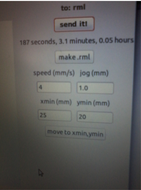
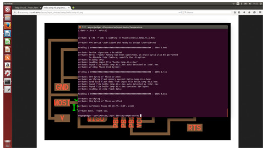
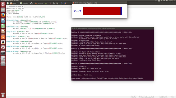
In the picture it shows the command used to load the application Python.
After running the application an additional window in which the temperature measured at the time shown appears.
STEP 6: CHECKING THE OPERATION OF THE APPLICATION
To verify that there is variation in temperature put our finger on the sensor and proceed to observe changes in temperature.
As an additional task the magnetic sensor, which operation is shown in the following video was built.