PORTABLE 3D PRINTER-SCANNER
STEP 6: ELECTRONIC DESIGN
Home
OBJECTIVE
- Redraw the echo hello-world board
- Add at least a button and a LED to my board
PROCEDURE
DOWNLOAD
1. Download and install Eagle (Easily Applicable Graphical Layout Editor), a software for routing, generating schematics and developing electronic boards.
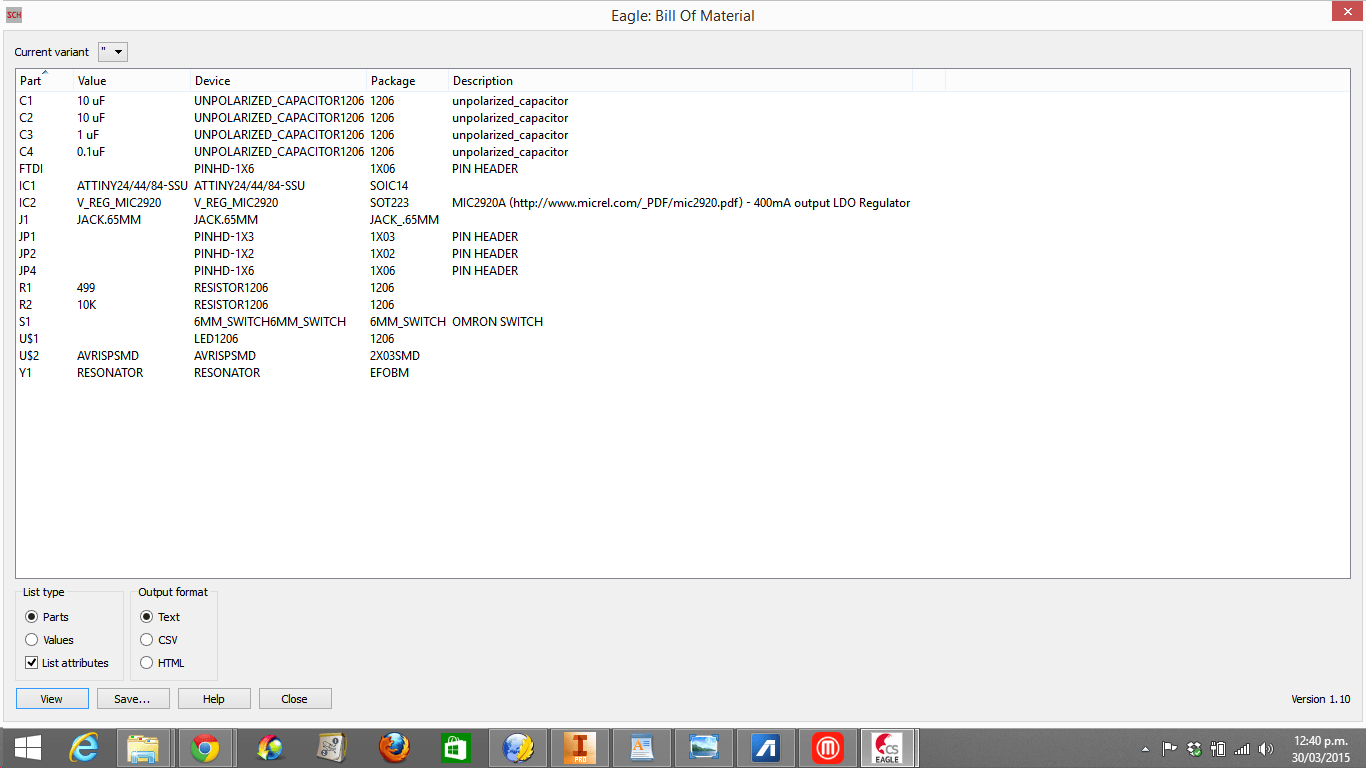
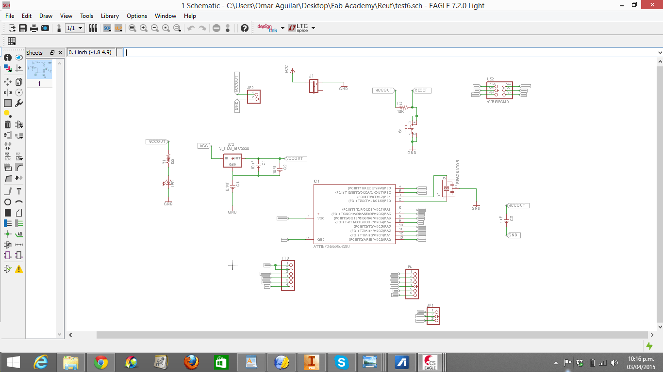
2.1. Open an Schematic in Eagle and Import the pieces of the echo hello-world board (the list of pieces is below)
OR
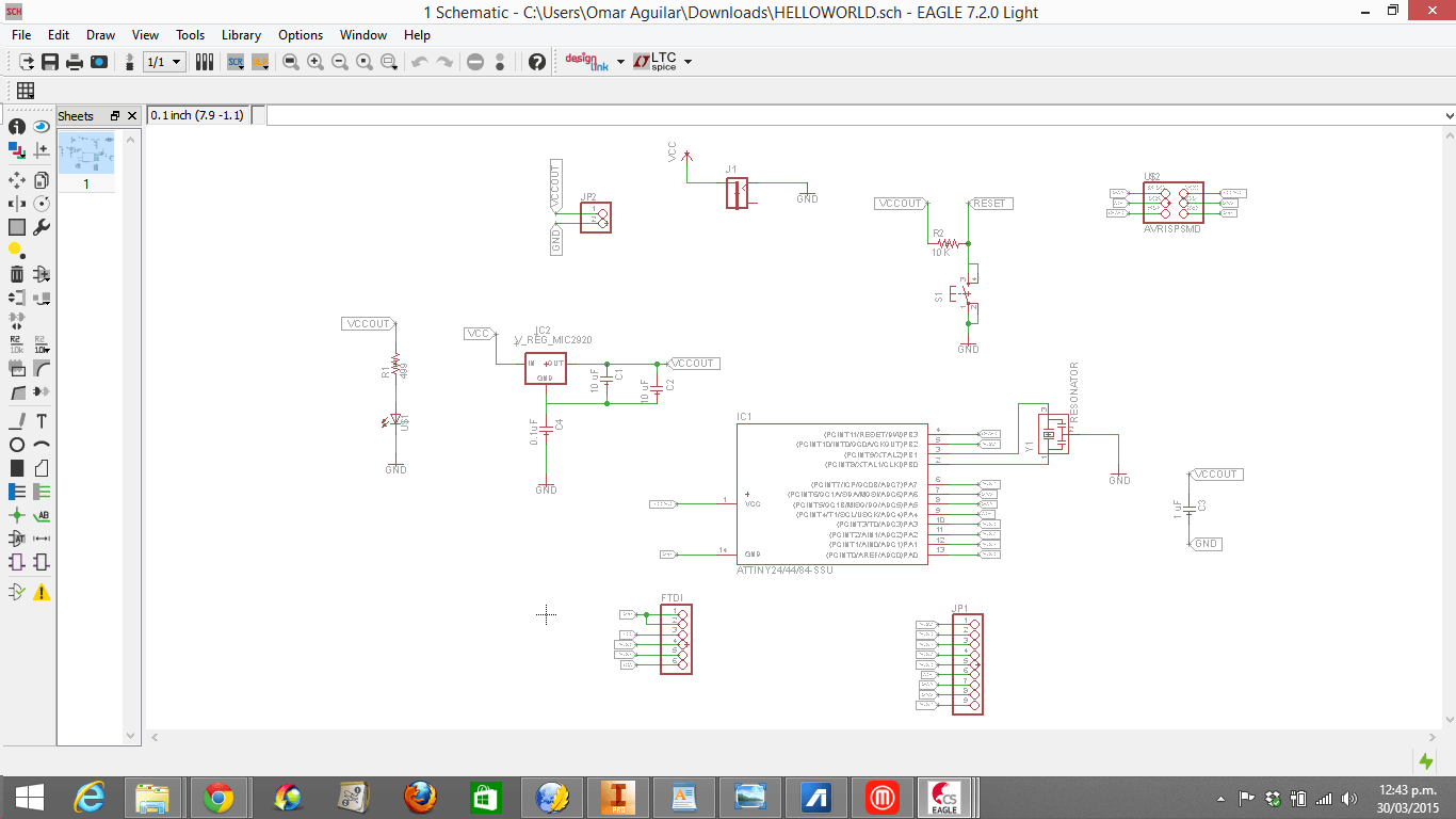
2.2. Download Fab Lab Tecsup's schematic created by Jose de los Ríos. https://www.dropbox.com/s/peu28wzu0wixnn4/HELLOWORLD.sch?dl=0
3. Download libraries and unzip them. https://www.dropbox.com/s/q3mo1yfac11cyhj/eagle_libraries.zip?dl=0
4. Open Eagle, choose Options and then Directories. Browse "eagle libraries" and click "OK". In Eagle control panel search, make a right click to "eagle libraries" and click "Use all".
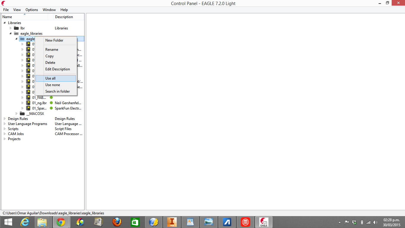
4. Open Eagle, choose Options and then Directories. Browse "eagle libraries" and click "OK". In Eagle control panel search, make a right click to "eagle libraries" and click "Use all".
REDRAW
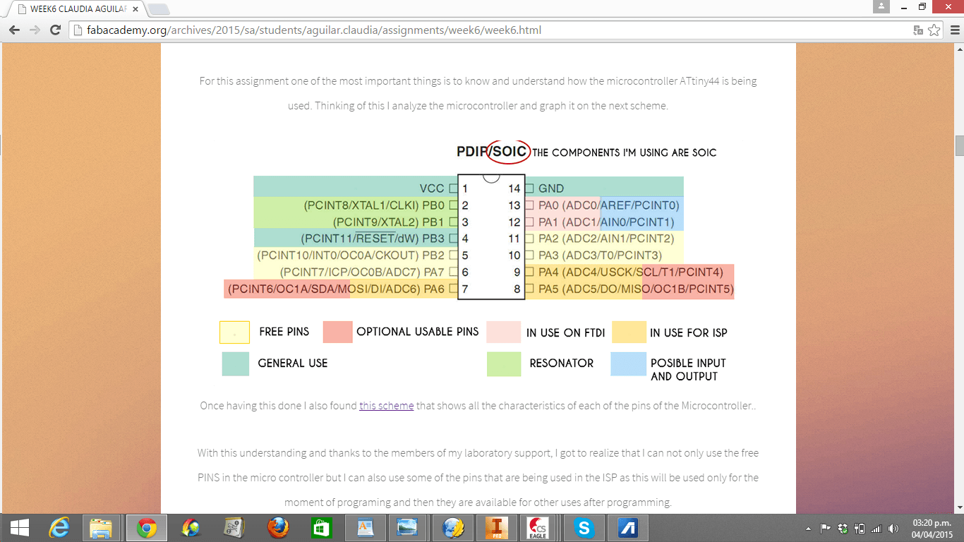
1. For understanding how the ATTiny 44 works, I read the second page of the ATTiny 44 data sheet. However, I did not understand why the ATTiny 44 was connected to each of the pieces in that way, so I read Claudia Aguilar's electronics design assignment, which is very clear. (Here is the link: http://fabacademy.org/archives/2015/sa/students/aguilar.claudia/assignments/week6/week6.html)
Requirements for an efficient board:
- ATTiny 44 should be in the center
- 0.1 uF Capacitor (C4), AVR and Resonator should surround around the ATTiny 44.
- Pins (FTDI, JP1, JP2 and JP4) and Jack power should be in the border of the board.
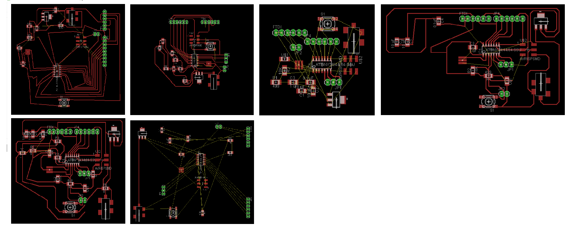
2. I had a lot of problems for creating routes in Eagle. Many routes intersected whenever I began routing, even when I used bridges. Consequently, my designs were not only messy, but also seemed inefficient for solding as they required lots of 0 ohm resistors and large spaces. (Below are all my messy boards)
1. For understanding how the ATTiny 44 works, I read the second page of the ATTiny 44 data sheet. However, I did not understand why the ATTiny 44 was connected to each of the pieces in that way, so I read Claudia Aguilar's electronics design assignment, which is very clear. (Here is the link: http://fabacademy.org/archives/2015/sa/students/aguilar.claudia/assignments/week6/week6.html)
Requirements for an efficient board:
- ATTiny 44 should be in the center
- 0.1 uF Capacitor (C4), AVR and Resonator should surround around the ATTiny 44.
- Pins (FTDI, JP1, JP2 and JP4) and Jack power should be in the border of the board.
2. I had a lot of problems for creating routes in Eagle. Many routes intersected whenever I began routing, even when I used bridges. Consequently, my designs were not only messy, but also seemed inefficient for solding as they required lots of 0 ohm resistors and large spaces. (Below are all my messy boards)
3. Roberto Delgado taught me a technique for routing more clearly and efficiently.
Rules:
- Enter to the Schematic board
- Choose a red piece (Ex. The LED circled in red)
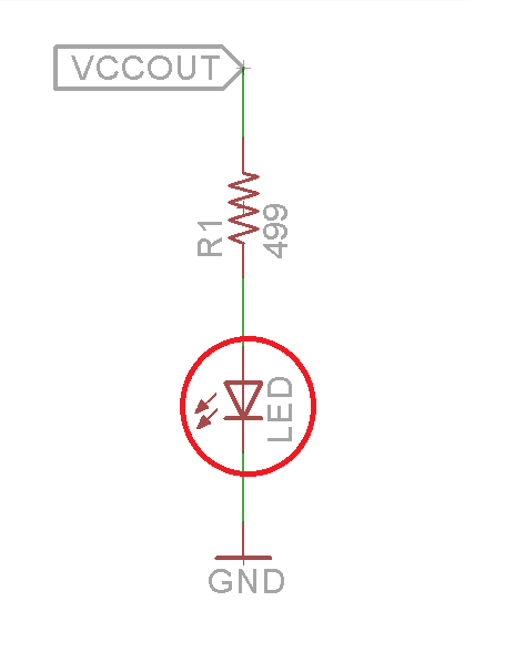
- Identify the red piece's neighbour red pieces
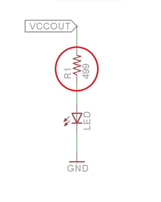
- Enter to the Route board
- Identify the piece that represents the chosen red piece
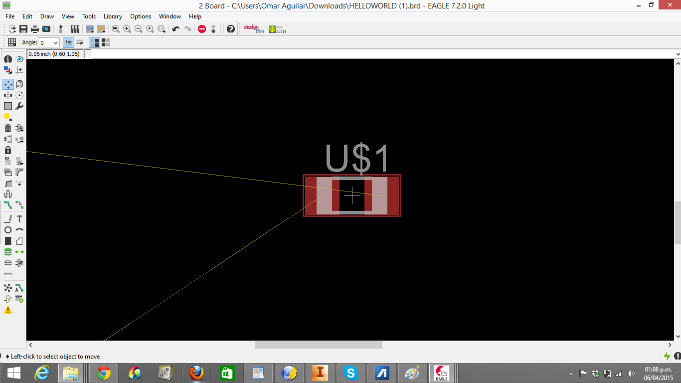
- Place the red piece next to its schematic neighbours
- Repeat the same process for all the red pieces
- Begin routing (I am almost sure there will not be overlapped routes)
Rules:
- Enter to the Schematic board
- Choose a red piece (Ex. The LED circled in red)
- Identify the red piece's neighbour red pieces
- Enter to the Route board
- Identify the piece that represents the chosen red piece
- Place the red piece next to its schematic neighbours
- Repeat the same process for all the red pieces
- Begin routing (I am almost sure there will not be overlapped routes)
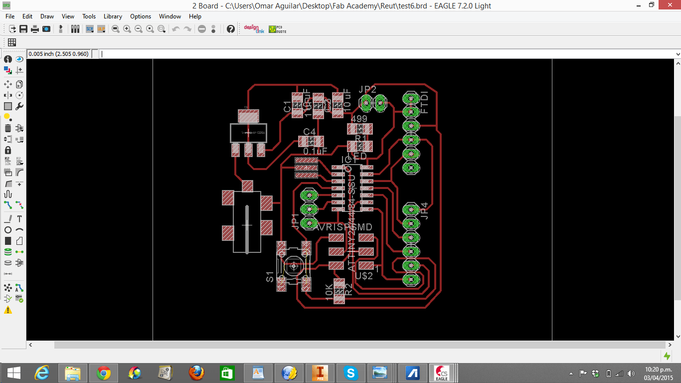
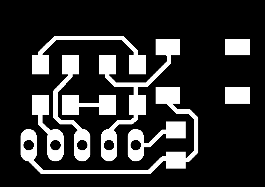
You can download the redraw echo-hello board here and schematic here.
4. I (unchecked) clicked on "Layer settings" -> "None" -> "Top", "Pads" and "Vias".
4. I (unchecked) clicked on "Layer settings" -> "None" -> "Top", "Pads" and "Vias".
5.
I clicked on File -> Export -> Image. Then I browsed where I
wanted to save my board, clicked "Monochrome", wrote "800" in resolution and clicked "ok".
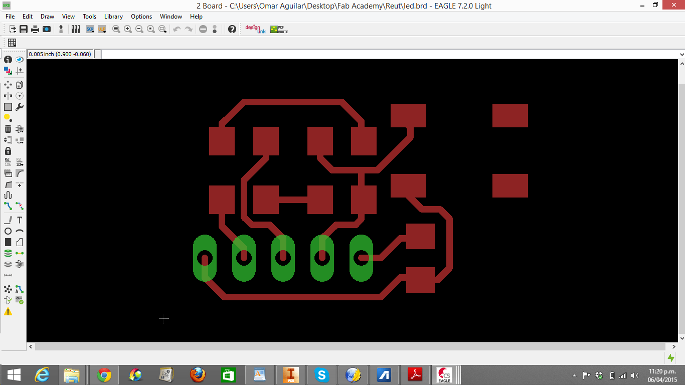
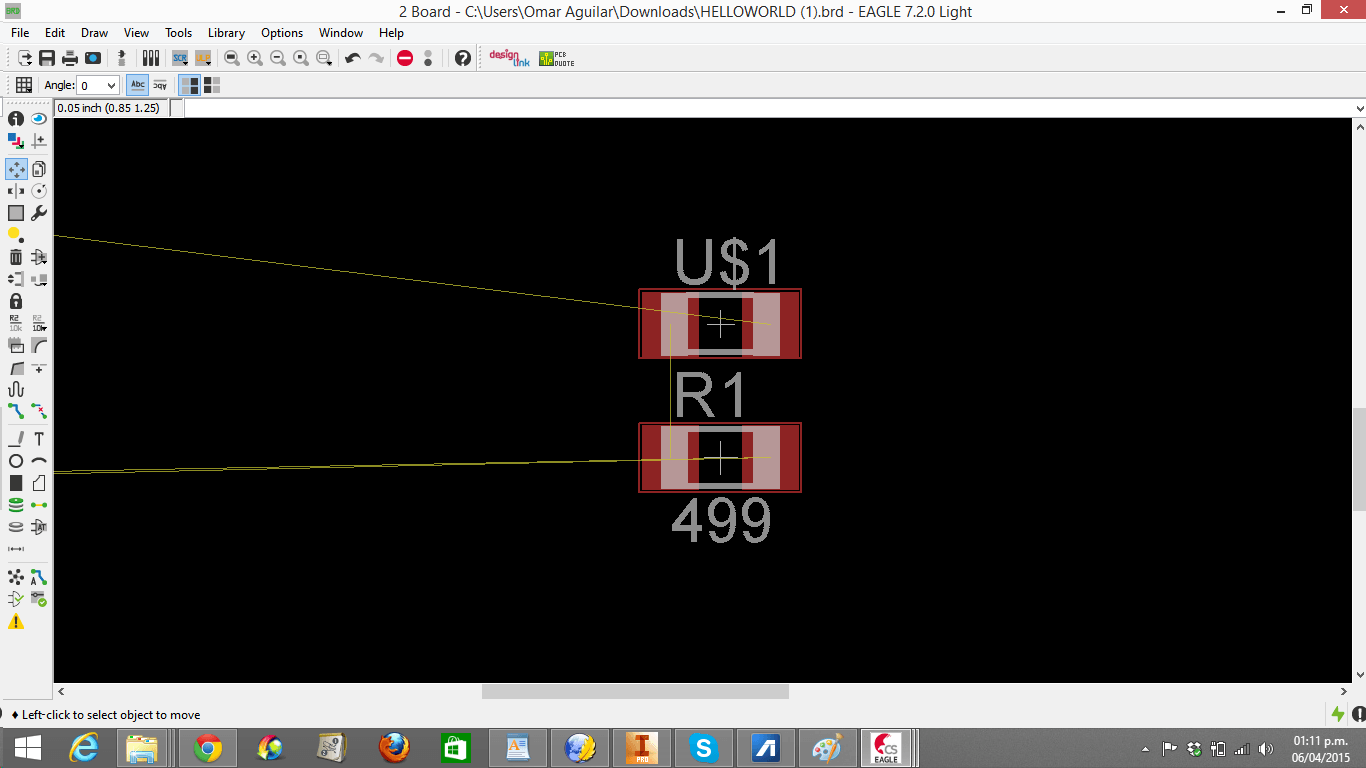
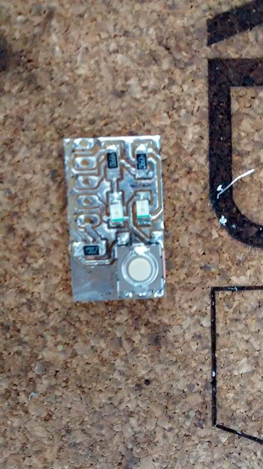
LED + BUTTON
1. I imported the pieces I needed (from the Fab_Hello library) for making a circuit that included a LED and a Button. Those were:
- LEDs (2)
- 499 ohm Resistors (2)
- 10 K ohm Resistors (1)
- 6mm Omrom Switch
- Pin Header of 5 pins
2. For the LED and switch, connect the same GND
3. The 5 pinhead distribution was the following one:
- 1---VCC
- 2---GND
- 3---LED#1
- 4---LED#2
- 5---SWITCH
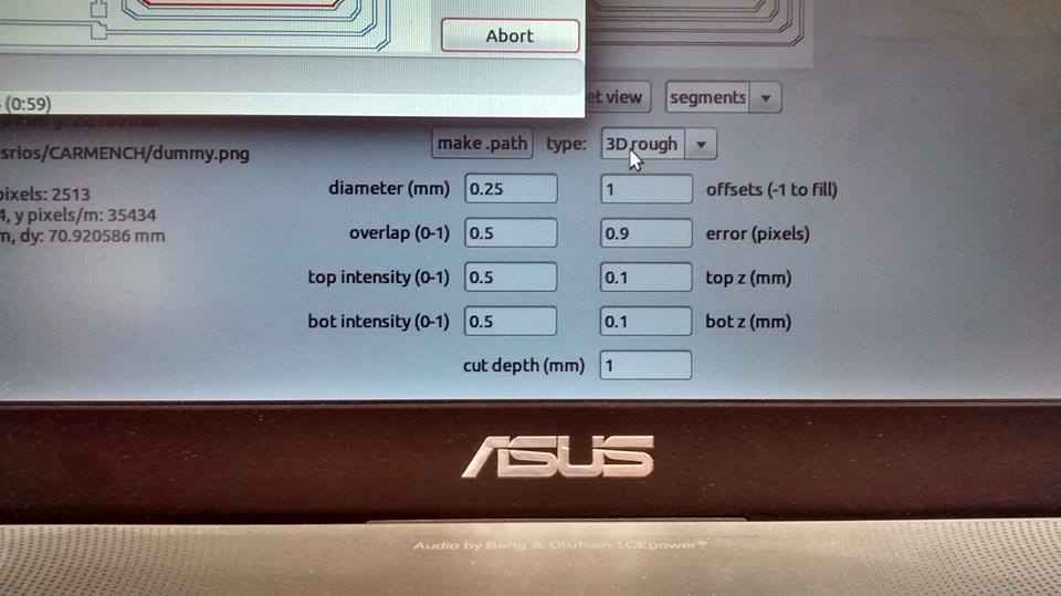
CUTTING
1. I followed the Week 4 procedure.
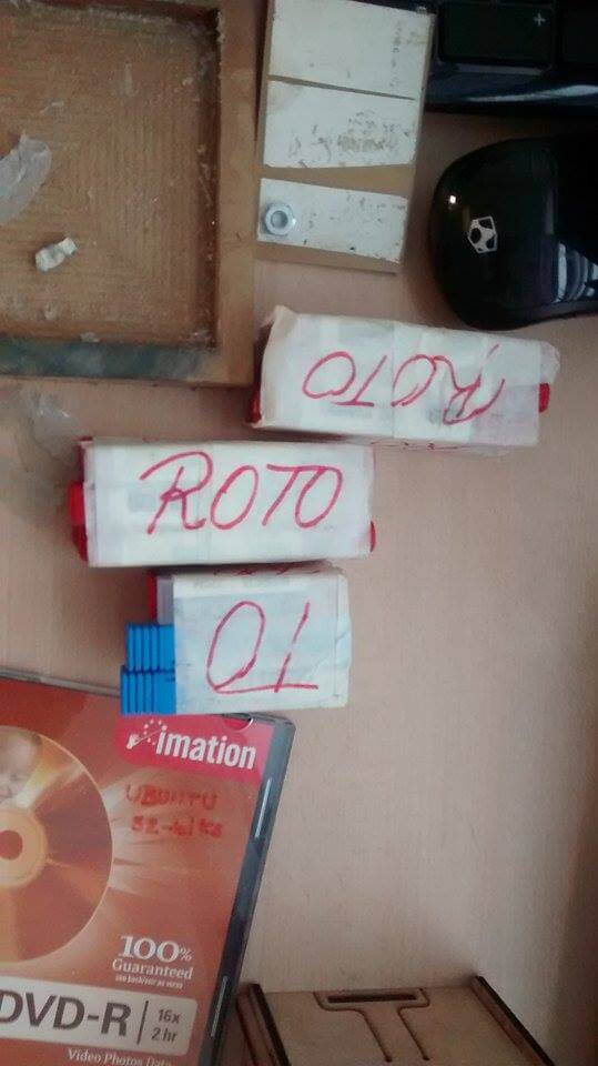
2. Because I did not calibrate well the Modela, I made 4 unuseful boards (in order: left to right) and broke 4 mills. My first board took the cooper out of the surface, the second board did not evrything, the third one cutted to much of the cooper and the fourth left a rough and unuseful cooper surface.
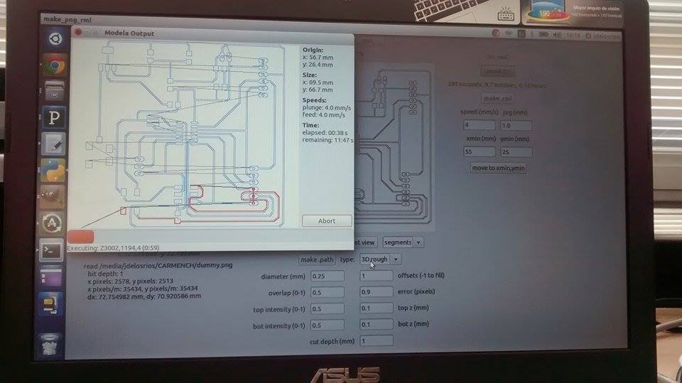
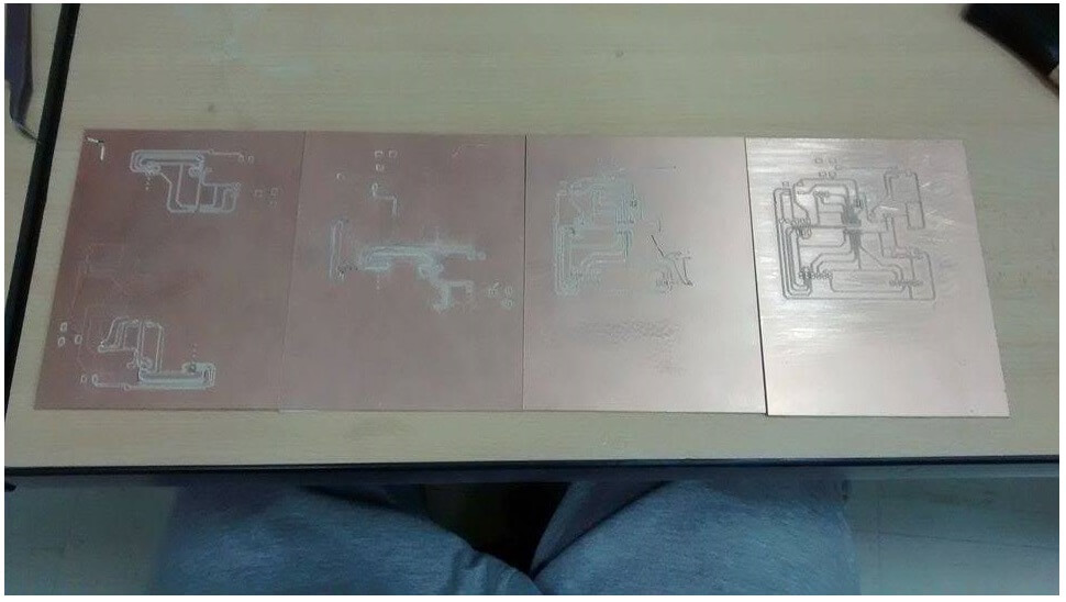
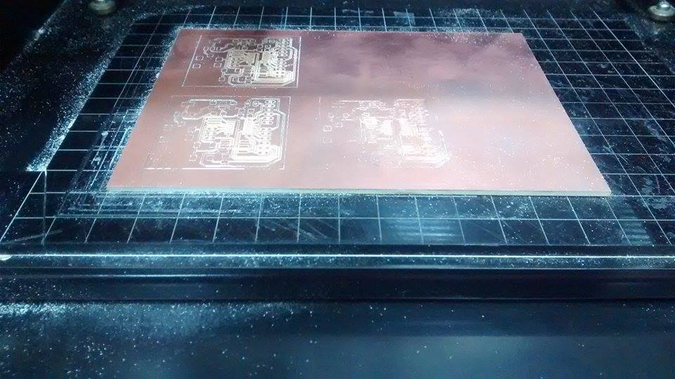
3. ....Finally, I was able to cut a descent board!
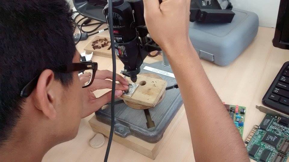
DRILLING
1. Check voltage. In this case, it should be 120V
2. Drill
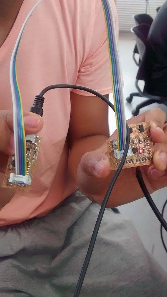
TESTING
1. Take a Multimeter AMPROBE 37XR-A
2. Select option "continuity" represented by waves
3. Verify (red=postive, black=negative)
4. With the help of the FabISP, an Ubuntu program (taken from Terminal) is charged to the board for making it programmable.
5. If the LED lights up, the board is ready!
CONCLUSIONS
1. Understand the function of every ATTiny44 pin and how every board piece is connected to each other
2. Follow Roberto Delgado's method for efficient routing
3. Never sold a board completely with a big solder stick, because you can burn the cooper
4. Do not create TOO narrow routes, because they are almost unsoldable. However, do not create width routes, because they take a lot of material.
5. Drill before solding, because a wrong drill can make a time-consuming solding unreperaible.
1. I imported the pieces I needed (from the Fab_Hello library) for making a circuit that included a LED and a Button. Those were:
- LEDs (2)
- 499 ohm Resistors (2)
- 10 K ohm Resistors (1)
- 6mm Omrom Switch
- Pin Header of 5 pins
2. For the LED and switch, connect the same GND
3. The 5 pinhead distribution was the following one:
- 1---VCC
- 2---GND
- 3---LED#1
- 4---LED#2
- 5---SWITCH
CUTTING
1. I followed the Week 4 procedure.
2. Because I did not calibrate well the Modela, I made 4 unuseful boards (in order: left to right) and broke 4 mills. My first board took the cooper out of the surface, the second board did not evrything, the third one cutted to much of the cooper and the fourth left a rough and unuseful cooper surface.
3. ....Finally, I was able to cut a descent board!
DRILLING
1. Check voltage. In this case, it should be 120V
2. Drill
TESTING
1. Take a Multimeter AMPROBE 37XR-A
2. Select option "continuity" represented by waves
3. Verify (red=postive, black=negative)
4. With the help of the FabISP, an Ubuntu program (taken from Terminal) is charged to the board for making it programmable.
5. If the LED lights up, the board is ready!
CONCLUSIONS
1. Understand the function of every ATTiny44 pin and how every board piece is connected to each other
2. Follow Roberto Delgado's method for efficient routing
3. Never sold a board completely with a big solder stick, because you can burn the cooper
4. Do not create TOO narrow routes, because they are almost unsoldable. However, do not create width routes, because they take a lot of material.
5. Drill before solding, because a wrong drill can make a time-consuming solding unreperaible.