PORTABLE 3D PRINTER-SCANNER
STEP3: COMPUTER-CONTROLLED CUTTING
Home
OBJECTIVE
- Learn about wood joints
- Build a structure with wood joints
PROCEDURE
1. I wanted to relate this assignment with my final project
2. I thought that my final project's wood joints were too simple for this assignment; therefore I chose to do another thing this time
3. I decided to build a desk that could be used for the assignment of Make Something Big
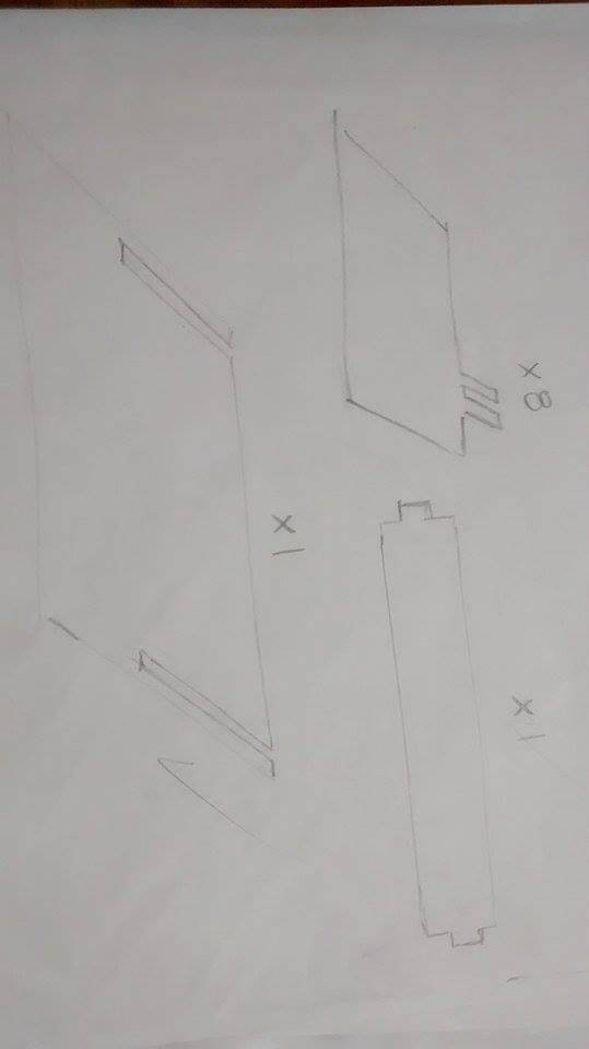
4. Here is my sketch
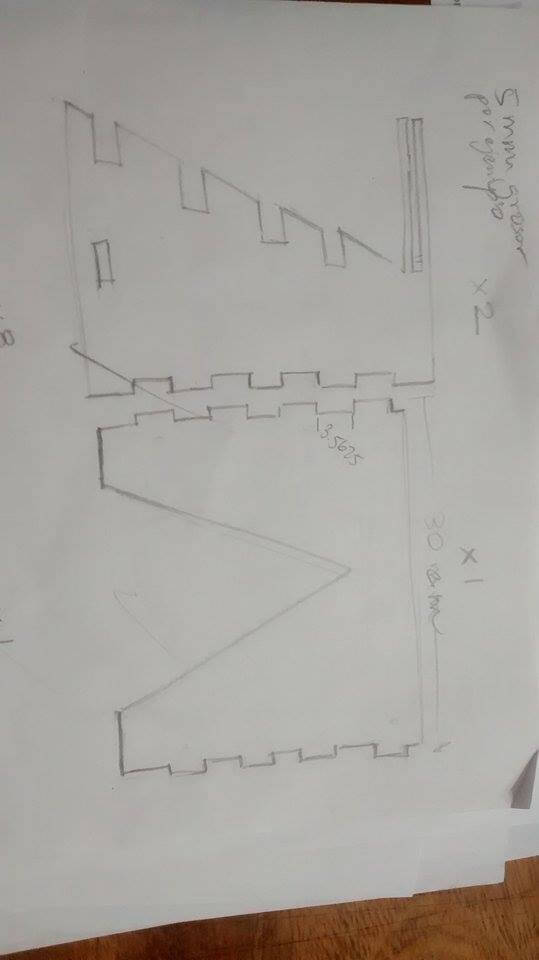
5. I searched the main types of wood joints, because I was driven to include them all. This is the main link I used: WOOD JOINTS
6. I designed my drawing in Inventor
8. I determined the lines I would have to change if the referential thickness was not right.
9. When I went to mhy Fab center, I found that the wooden piece's thickness was 4mm; therefore, I changed it.
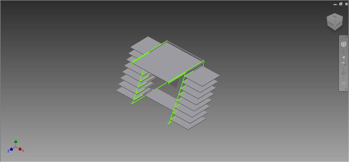
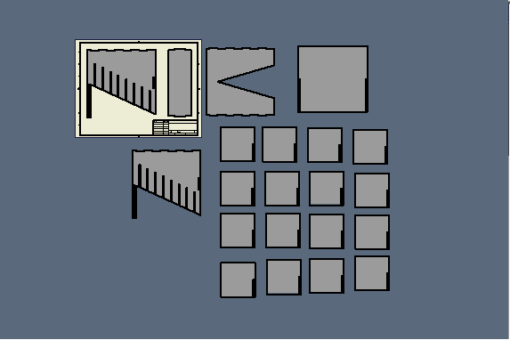
10. I exported my designs to Rhinoceros
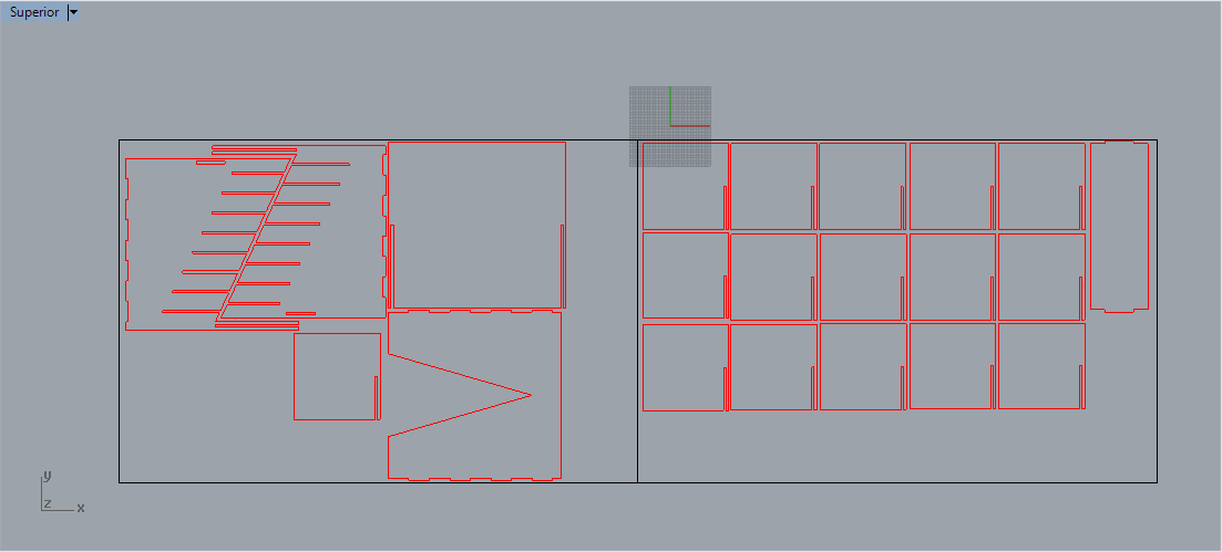
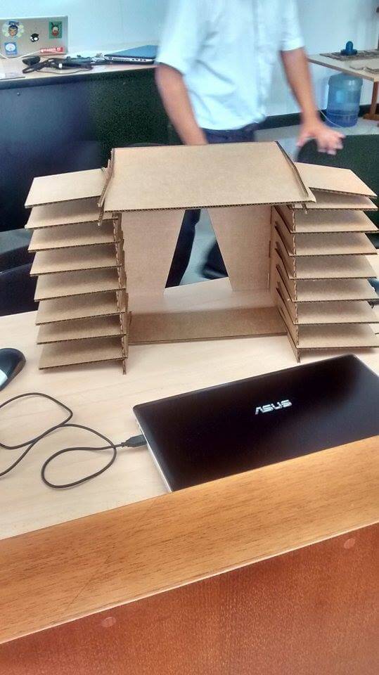
13. Here are my parts after assembly
CONCLUSIONS
1. Narrow cartboard pieces are weak
2. Too much weight at both sides of a structure can cause it to fall instead of balance its weight.
3. It is really important that the dovetail joints should have trapezoid shapes.
4. After experimenting with cartboard joints, I realized that I could have applied them to my final project...they were not that simple.
AFTERWARDS
I talked with Miguel, a Mechanical Technician at TECSUP about ways for improving my final project design according to my observations in Step 2. These were the results:
1. For strengthen the 3D Printer part of my final project while using hinges, I can make some holes in my blocks and put removable pins.
2. For completely folding my machine I can increase the height of the wall below the 3D Printer part.
3. If I use a small valve with a tube, my container can be at the same level of my machine.
4. My blocks can have half their actual height and some sliders below (to make it movable)
5. My Y-axis can be folded like a 2D Printer top part, instead of going out of the structure.
6. An L-zone shape is compulsory for filling the entire square zone of my machine.
FURTHER WORK: OBJECTIVE
I will design my final project with a structure at a 300 mm scale for making it more easy to work with, using joints.
1. I will search for more types of press fits now that I have watched how other people did the assignment in the Fab Latin America network.
2. I will try apply as many press fits to my final project new design while caring about its efficiency.
3. I will cut my new design.
FURTHERWORK: PROCESS
DESIGN
1. I observed the fitting-ins of Luis Peña's final project and I realized that once you put them in, you could not put them out.
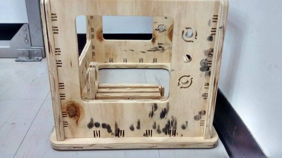
2. I decided to adapt this fitting-ins to final project and began measuring the lengths of another machine's fitting-ins with a pencil and a ruler.
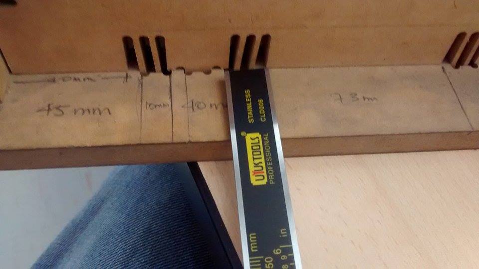
3. Then, I applied Cross Multiplication
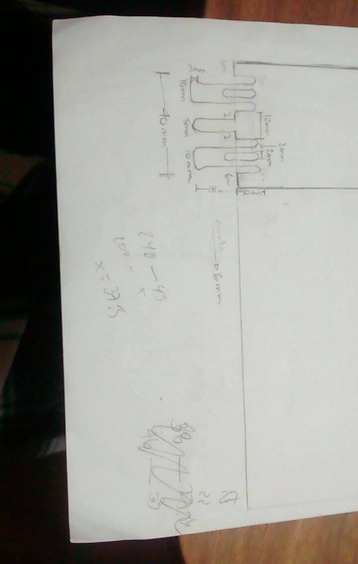
4.
I designed my project using fitting of two lengths: 35 mm and 19 mm. I
should say Inventor gave me trouble when I wanted to correct drawings,
because I could not extrude them easily. I recommend to copy the
correction to a New File and extrude it there.
SOFTWARE AND EPILOG
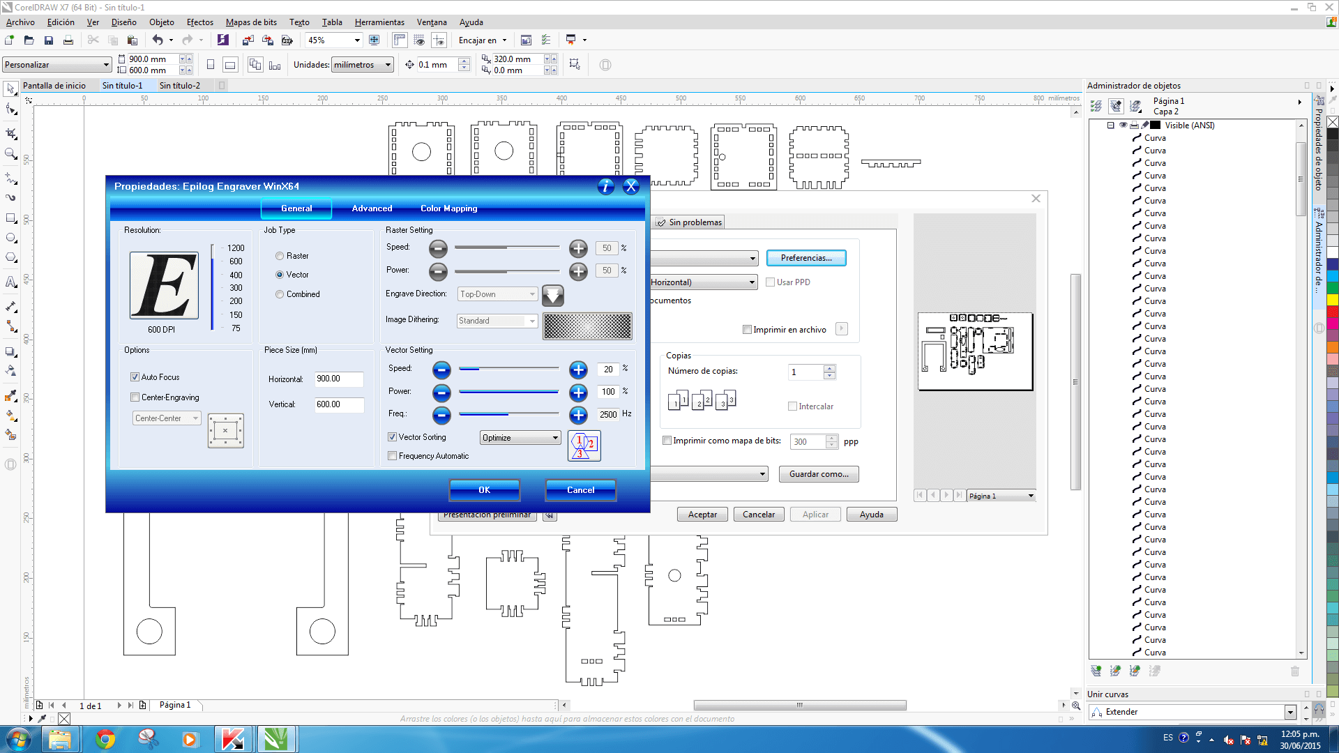
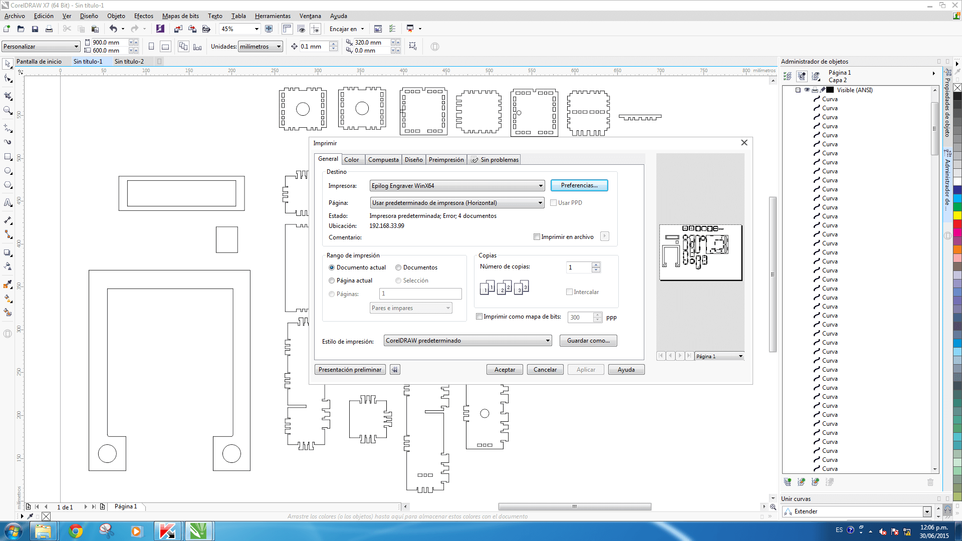
1. I opened Corel DRAW -> I imported my design in pdf format as you can see Here -> I clicked on Print -> I clicked on Preferences
2. Here are is the data I entered:
- Job Type: Vector
- Piece Size: 900 (Horizontal) and 600 (Vertical)
- Options: Autofocus (just that)
- Vector Setting: 20 (Speed), 80(Power) and 1500(Frequency)
3. I clicked on OK
4. I clicked on Accept.
5. I put the material I wanted to cut inside the Fab Epilog
6. I closed the Fab Epilog door
7. I confirmed that the gas filter and the air assistance were on
8. I pressed 'Job'
9. Using up and down arrows I found my archive
10. I pressed 'Reset' for starting from x0,y0
11. I pressed 'Go'
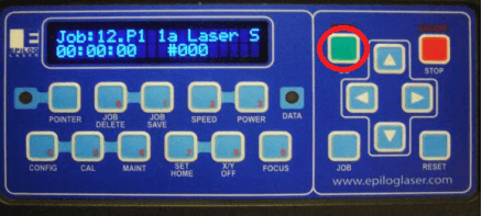
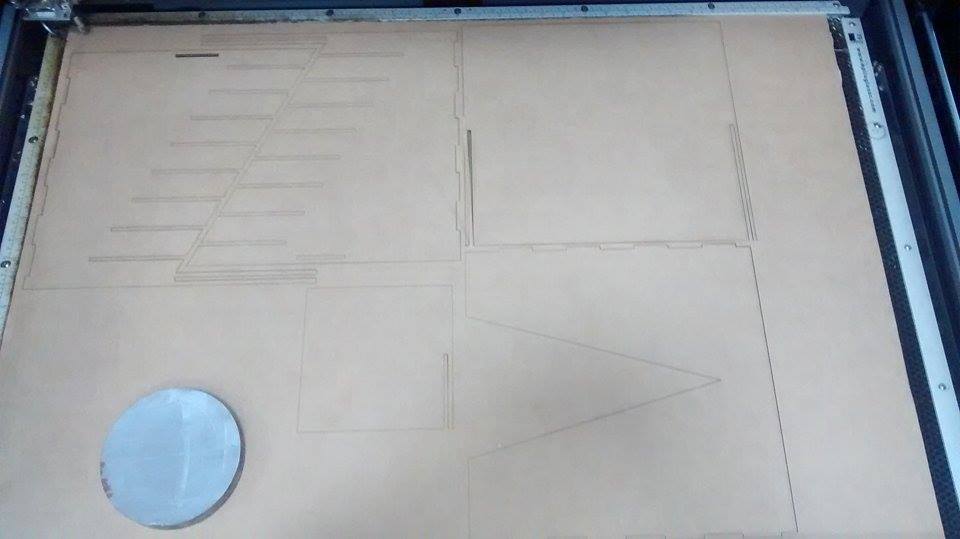
The picture above has been modified from this archive, due to its clear resolution (my camera has not very good resolution).
CUT
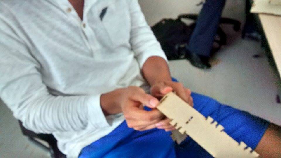
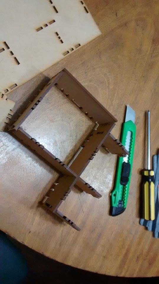
1. I cutted my project.
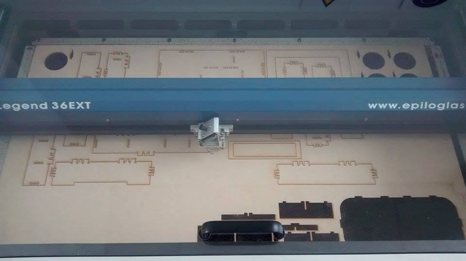
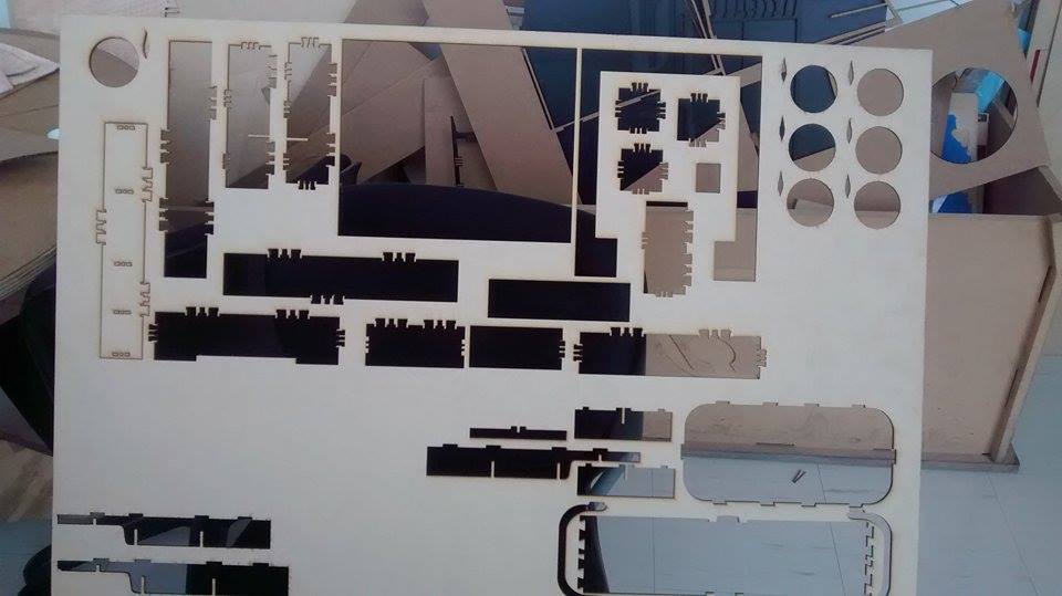
2. Three of my projects' pieces had mistakes. The first one was broken in one side, the second one didn't cut a fitting-in and the third one didn't cut the frame well (I had to break it).
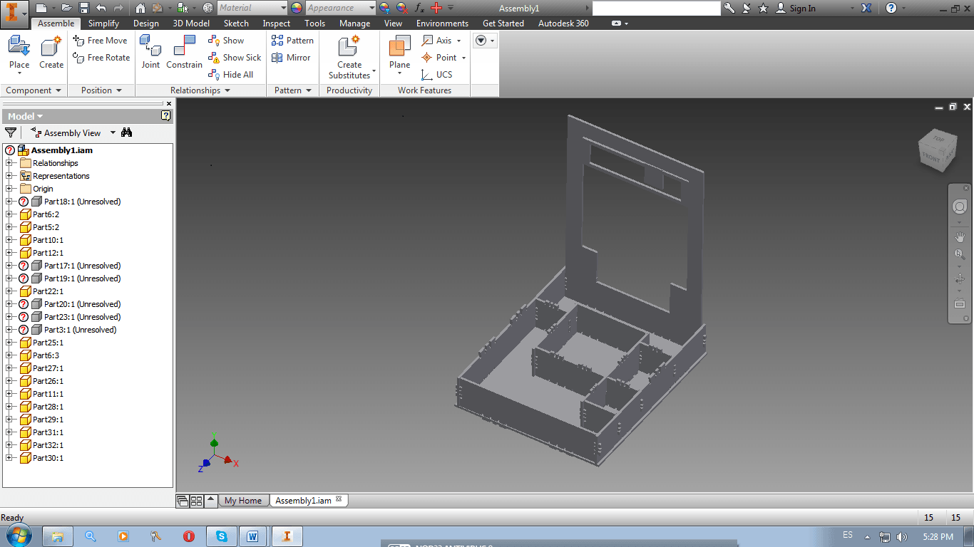
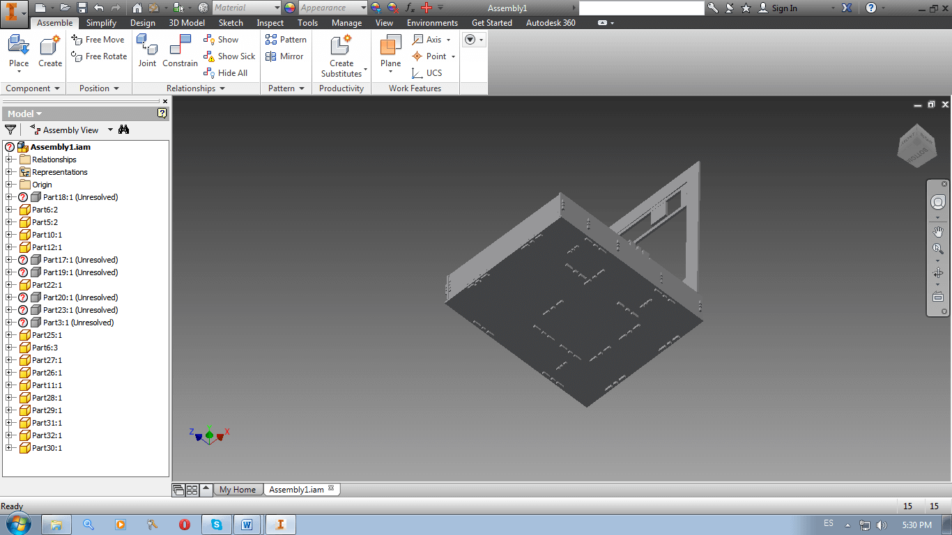
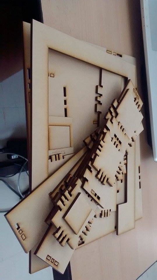
3. I tried to figure out what was the best way to assemble my project. I first thought I needed to add everything to the base in order to assemble hole by hole.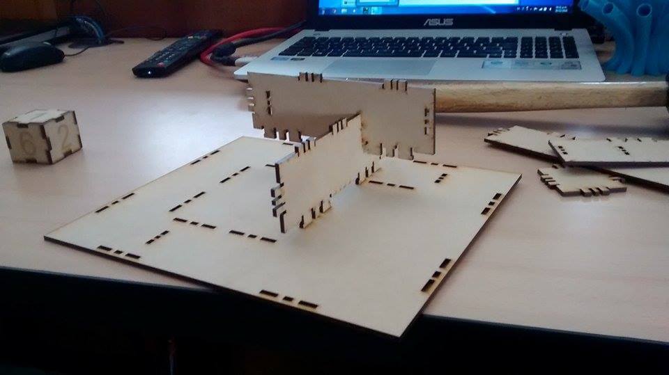
You can download the Assembly here and the press-fit kit in dwg. format here.
CONCLUSIONS
1. I should make tests before cutting everything. In this assignment, I made the male fitting-in 1mm bigger than the female fitting-in and I wasn't able to connect them easily. That's why I used a hammer.
2. The fitting-ins need to have circular ends in order to to make better insertions.
3. Fitting-ins should be placed not so near the borders of the base or they will break apart.
SOFTWARE AND EPILOG
1. I opened Corel DRAW -> I imported my design in pdf format as you can see Here -> I clicked on Print -> I clicked on Preferences
2. Here are is the data I entered:
- Job Type: Vector
- Piece Size: 900 (Horizontal) and 600 (Vertical)
- Options: Autofocus (just that)
- Vector Setting: 20 (Speed), 80(Power) and 1500(Frequency)
3. I clicked on OK
4. I clicked on Accept.
5. I put the material I wanted to cut inside the Fab Epilog
6. I closed the Fab Epilog door
7. I confirmed that the gas filter and the air assistance were on
8. I pressed 'Job'
9. Using up and down arrows I found my archive
10. I pressed 'Reset' for starting from x0,y0
11. I pressed 'Go'
CUT
1. I cutted my project.
2. Three of my projects' pieces had mistakes. The first one was broken in one side, the second one didn't cut a fitting-in and the third one didn't cut the frame well (I had to break it).
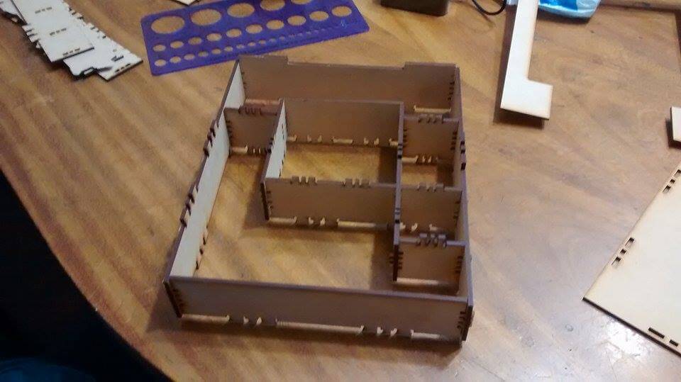
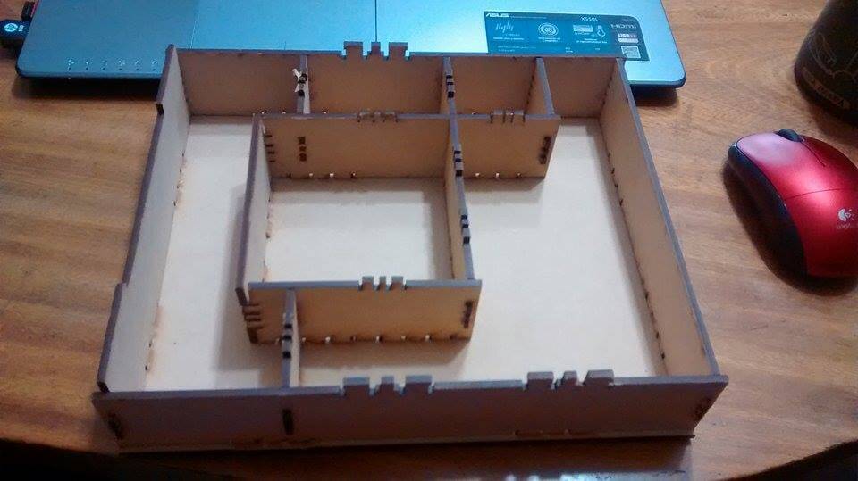
3. I tried to figure out what was the best way to assemble my project. I first thought I needed to add everything to the base in order to assemble hole by hole.
4.
Then I realized that as I went through, there were some pieces I could
not add, because they were being blocked by the pieces that surrounded
them. So I decided to assemble the walls first, then the internal
structure and finally the base.
You can download the Assembly here and the press-fit kit in dwg. format here.
CONCLUSIONS
1. I should make tests before cutting everything. In this assignment, I made the male fitting-in 1mm bigger than the female fitting-in and I wasn't able to connect them easily. That's why I used a hammer.
2. The fitting-ins need to have circular ends in order to to make better insertions.
3. Fitting-ins should be placed not so near the borders of the base or they will break apart.