PORTABLE 3D PRINTER-SCANNER
STEP 2: COMPUTER-AIDED DESIGN
Home
OBJECTIVE
- Model the Final Proposal
- Learn to use different desing softwares
PROCEDURE
1. This week I observed my sketch more carefully and realized that I had not figure out how the Y axis of my machine was going to move.
2. I tried to draw a solution for two days, but nothing came out as I did not know if there where were the empty spaces. Eventually I realized that the first step was not to make the Y axis move, but to understand my drawings clearly.
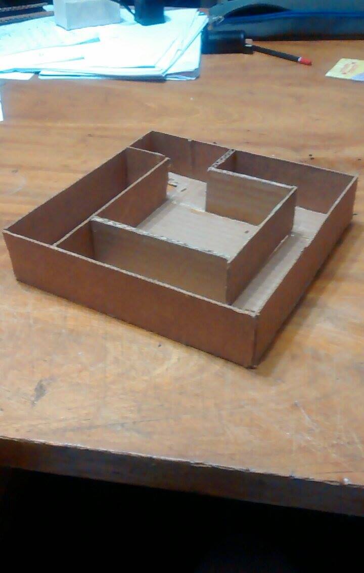
3. I decided to build my idea using cartboard and a cutter.
4. After building the structure of my machine, it was more easy to think just on the Y axis, because I had rid off my spatial doubts.
5. First I thought of Pulleys system, but then I discarded it, because it interferred with the 3D scanner's function, was not cheap and was mainstream.
6. Then, I thought about the Hart A frame mechanism (look this link: HART A MECHANISM), but after feedback from mechanical engineers from the Fab Lima, I comprehended that it was unnecessarily complex.
7. Finally, I found the Scott Russel mechanism (look this link: SCOTT RUSSEL MECHANISM). It did not have any of the problems the other alternatives had.
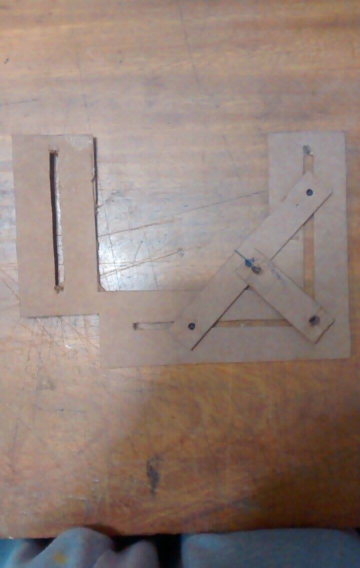
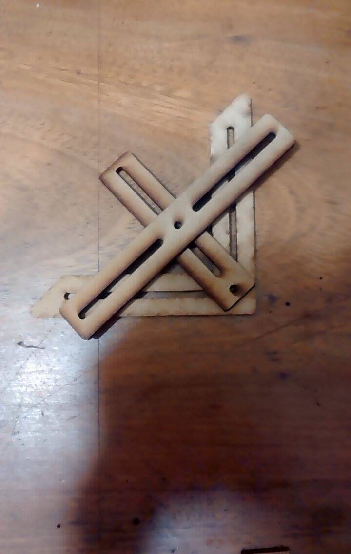
8. As there were no instructions on how to build the Scott Russel mechanism, I deduced its pieces' length by looking the video above and cutting the pieces in the CNC through trial and error.
3rd Scott Russel Model: One of the holes of the short lined piece is at half of the large lined piece's length (Made at HOME)
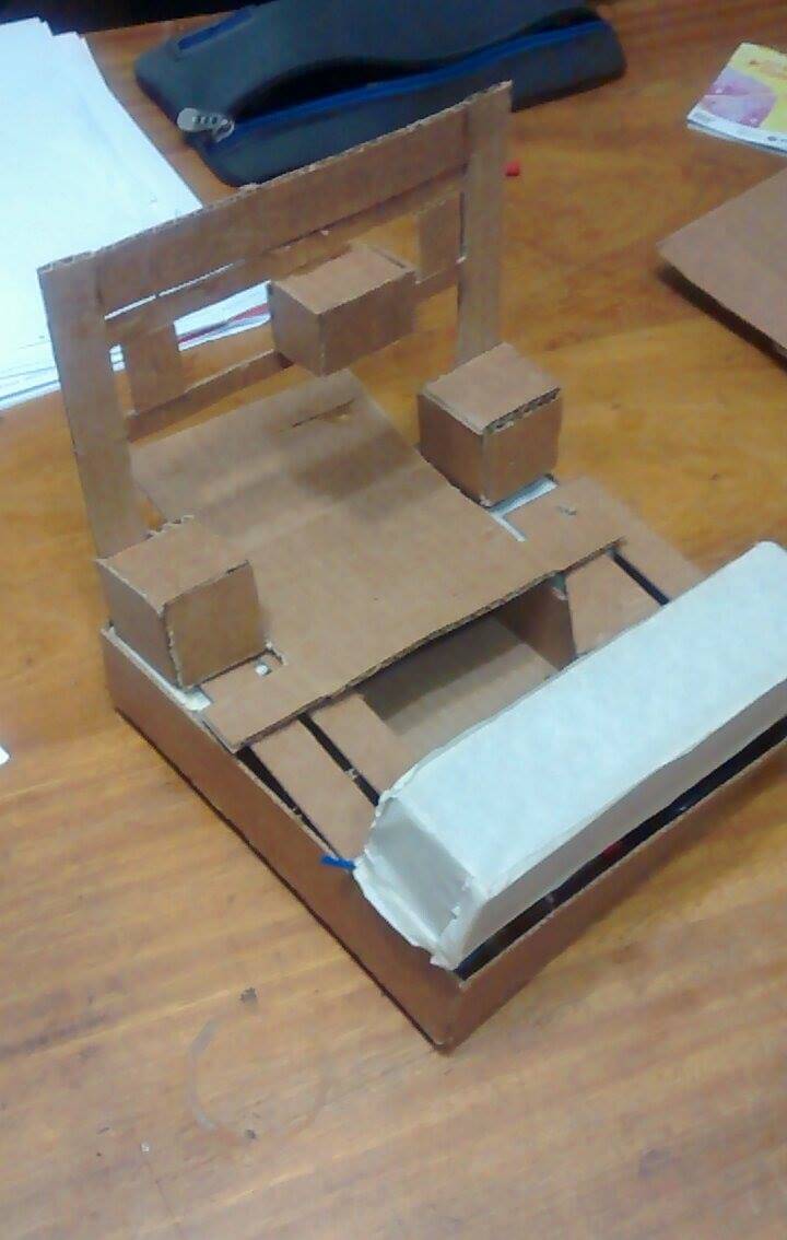
9. I finished my cartboard design.
10. Although, now I was able to clearly design my idea in my computer, the process of using cartboard took a lot of time. Therefore, I decided to design my machine in Inventor (because of recommendations by Fabbers) without a previous testing of other software.
11. I designed and assembled each piece in the same order I built my machine in cartboard.
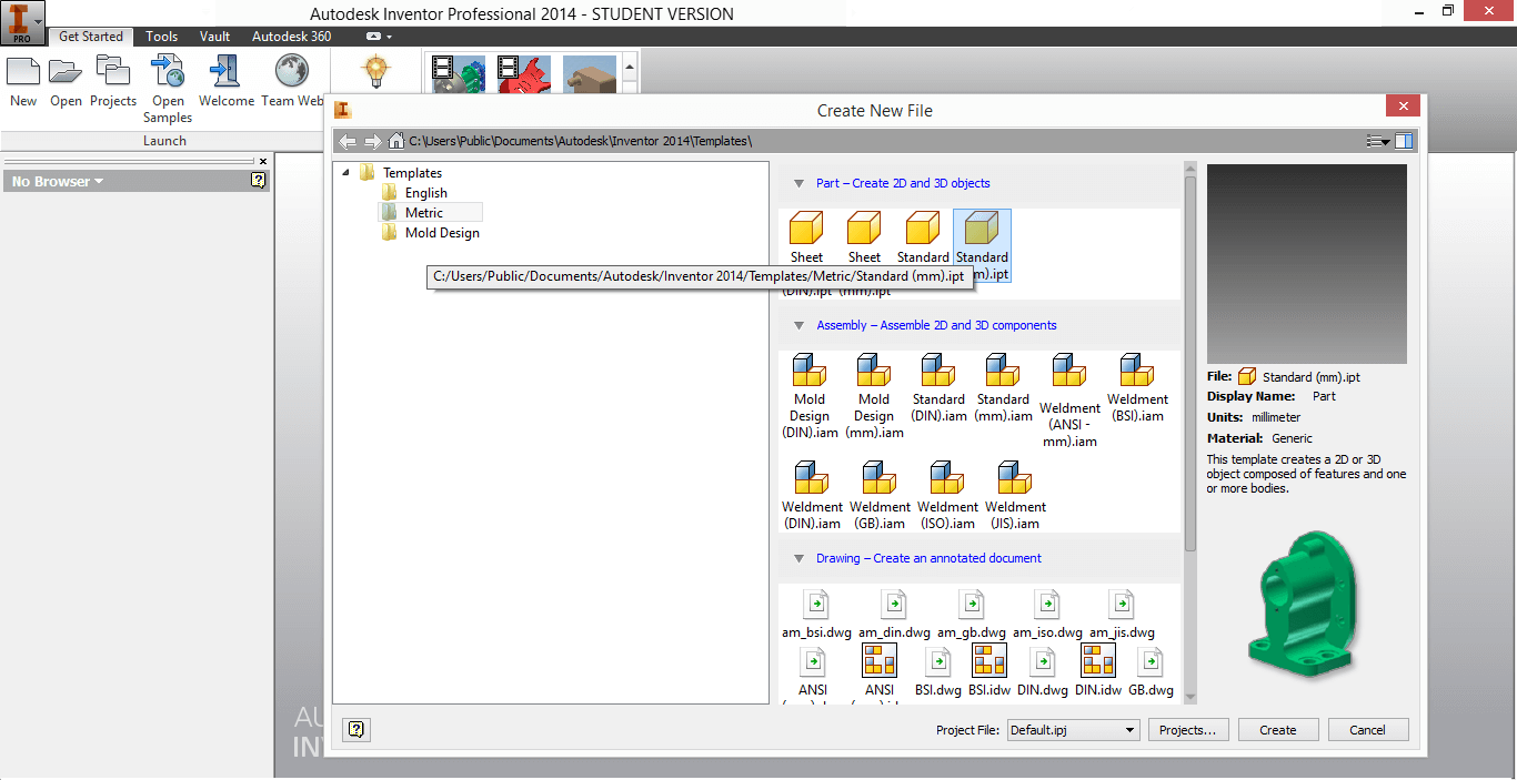
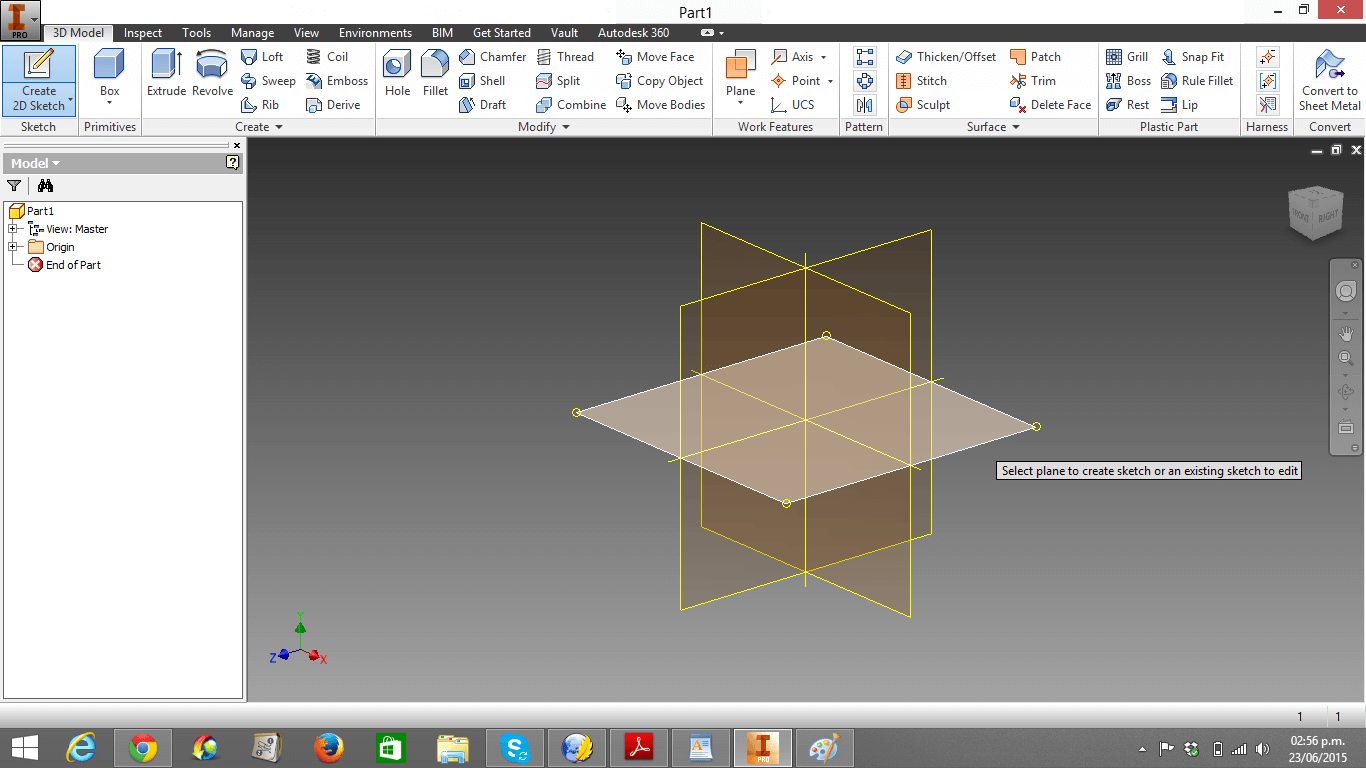
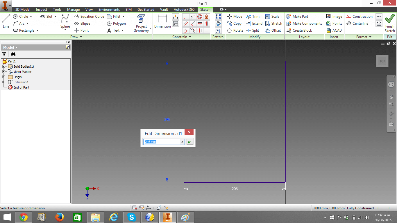
12. I opened Inventor -> clicked New -> clicked Standard (mm).ipt
13. I clicked Create 2D sketch and clicked in the centered plane.
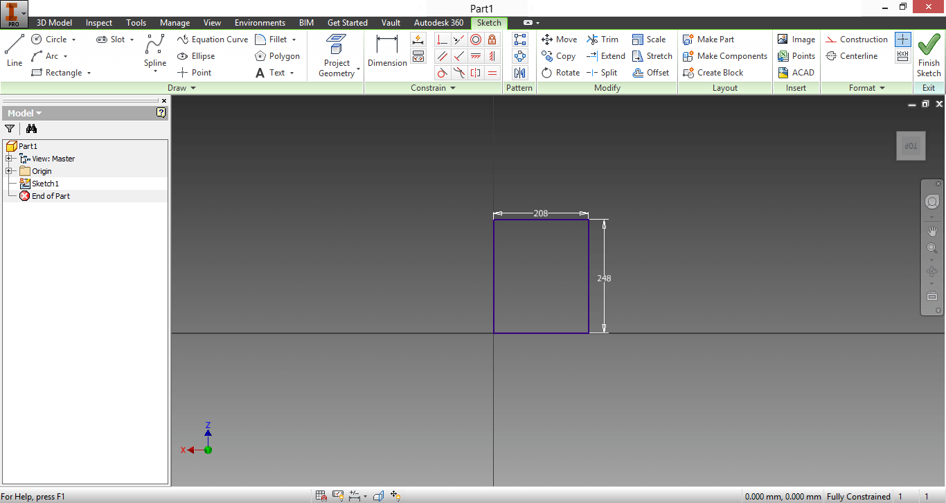
14. I made a 208mmx248mm rectangle using the option Rectangle in the Sketch Menu
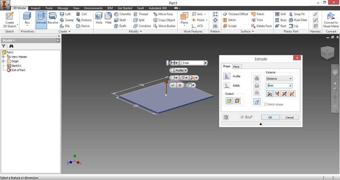
15. I clicked on Finish sketch and the design moved to diagonal position -> I clicked Extrude in the Tool Menu -> Change 10mm for 3mm -> Clicked in the rectangle surface. Thus, I had created a 3D picture.
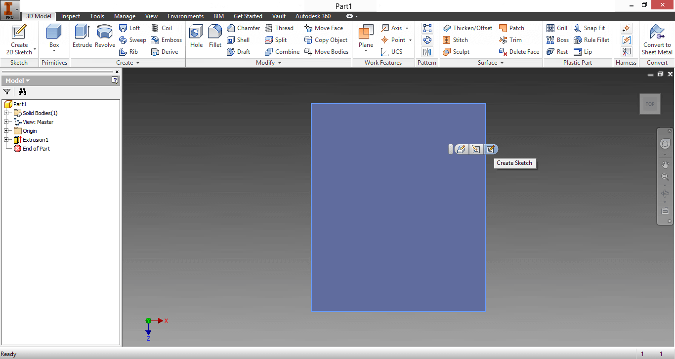
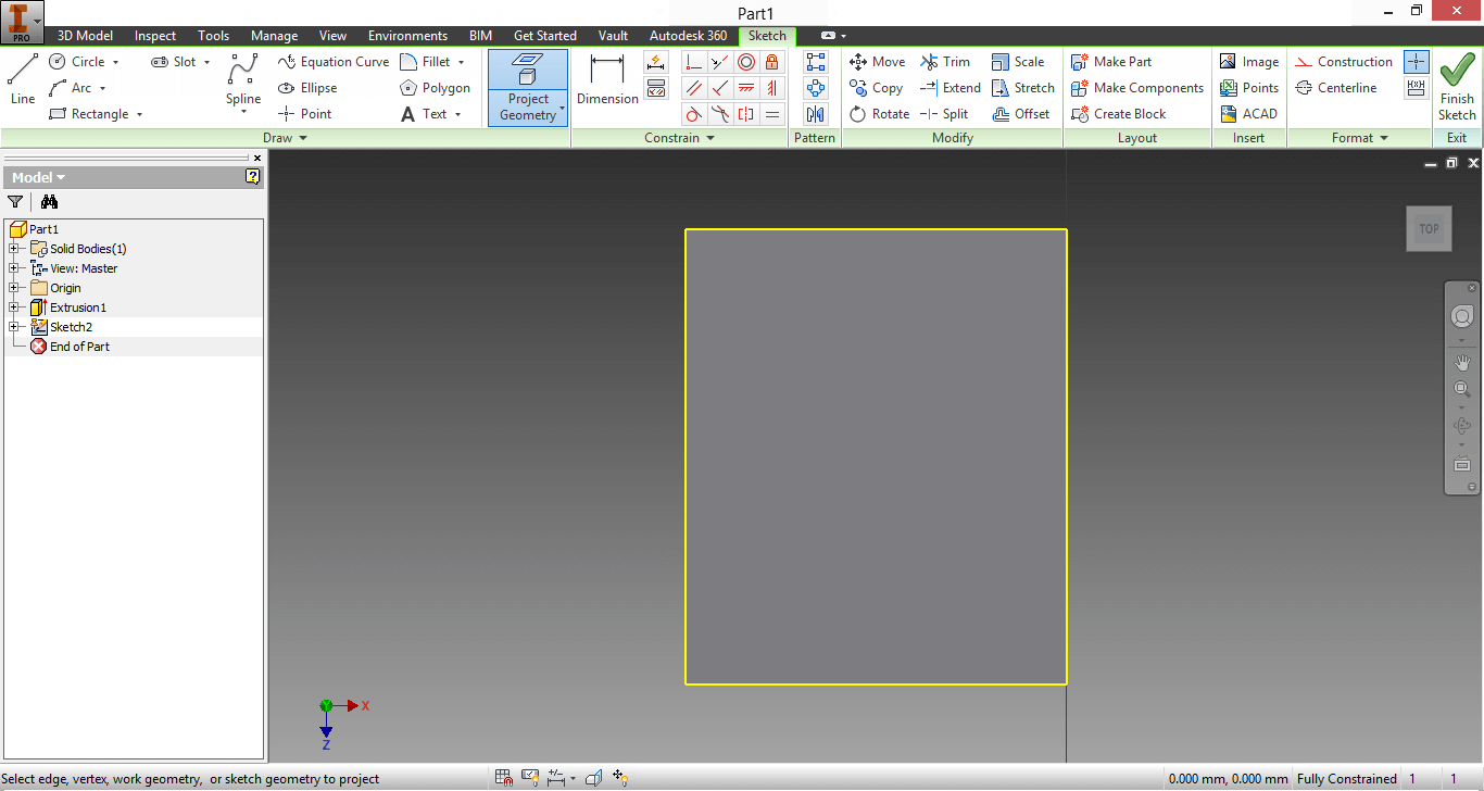
17. I clicked on Top -> I clicked in the gray surface -> I clicked the right botton that said "Create Sketch" when you stayed more than 1 second on it ->
BLOCK FACING VALVE
You can download my Asssemby of the foldable machine here and the unfoldable machine here.
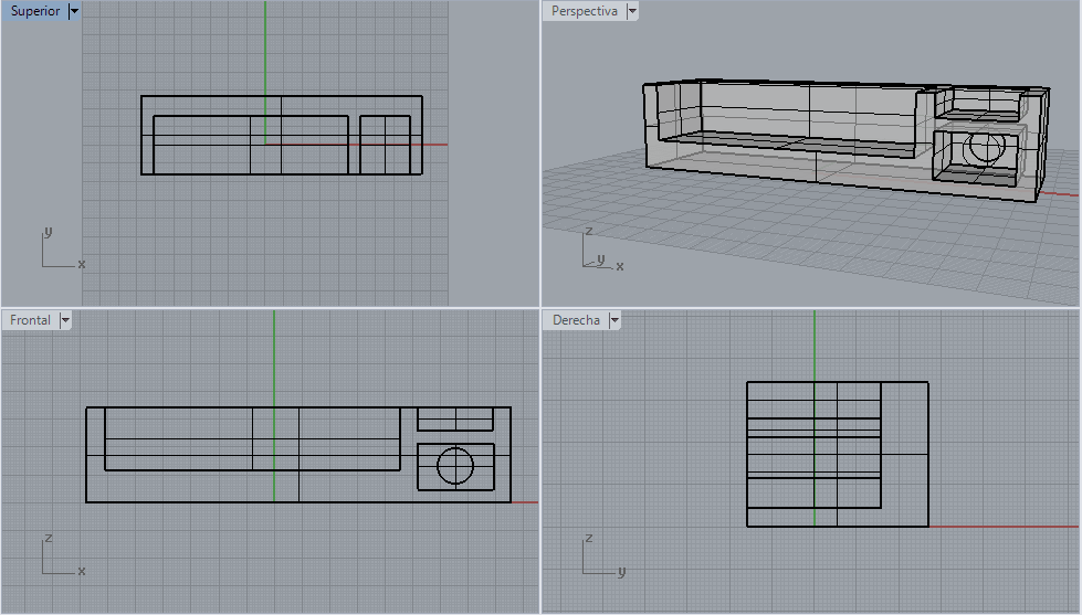
12. I just designed the container in Rhinoceros.
13. Last, I compared the two softwares (look below)
1. Inventor is more intuitive than Rhinoceros, as it does not need to use options such as "Difference" to make holes.
2. Inventor uses constraints, which makes it hard to erase mistakes. On the other hand, Rhinoceros does not uses constraints.
3. Inventor allows to assemble pieces more precisely and easily.
-> Inventor Wins! 2-1
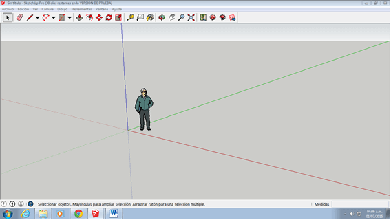
14. For being honest, I lost my Rhinoceros file and I am not very fluent in it. I decided to experiment with another software that would allow me to approach design through an intuitevely way: I designed in SketchUp. Here you can download my design.
15. First, I opened SketchUp after selecting the Millimeters option
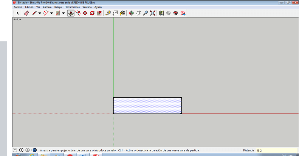
17. Clicked on Camera -> Clicked on Standard Windows -> Clicked on Top -> Clicked on the rectangle with the arrow -> Wrote 43.2
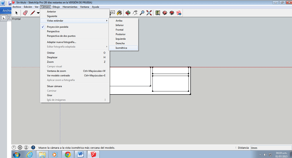
18. Clicked on Camera -> Clicked on Standard Windows -> Clicked on Frontal -> Clicked on the Pencil button-> Make inner walls of the container -> Clicked on Isometric
19. Clicked on Circle -> Make a Circle inside the Container
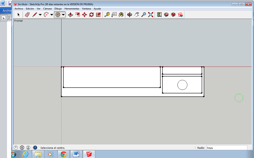
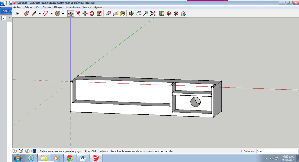
20. Clicked on the rectangle with the arrow -> Extrude circle until reaching the wall
Last, I compared the previous winner with SketchUp (look below)
1. Both softwares are very intuitive. I did not have to use any Difference command for substracting extrusions in any of the softwares.
2. Inventor uses constraints, which makes it hard to erase mistakes. On the other hand, SketchUp does not uses constraints.
3. Inventor allows to assemble pieces more precisely and easily.
-> Tie, I think that both softwares are very useful, but Inventor should be used for detailed and complex staff while SketchUp should be used for simple things that can be done in less time.
OBSERVATIONS
1. The hinges of the foldable Ian Moyer pieces are not shown
2. The hinges of the foldable Y-axis slider are not shown
3. The screws that connect most of the pieces are missing
4. Another Scott Russel Mechanism for enlarging the 3D Scanning zone is missing
5. As the surface of the machine has a slider and a mechanism (not a plain surface), a way of completely folding the machine needs to still be figured out
6. The pulleys of the Ian Moyer's mechanism are not shown
OBJECTIVE
- Model the Final Proposal
- Learn to use different desing softwares
PROCEDURE
1. This week I observed my sketch more carefully and realized that I had not figure out how the Y axis of my machine was going to move.
2. I tried to draw a solution for two days, but nothing came out as I did not know if there where were the empty spaces. Eventually I realized that the first step was not to make the Y axis move, but to understand my drawings clearly.
3. I decided to build my idea using cartboard and a cutter.
4. After building the structure of my machine, it was more easy to think just on the Y axis, because I had rid off my spatial doubts.
5. First I thought of Pulleys system, but then I discarded it, because it interferred with the 3D scanner's function, was not cheap and was mainstream.
6. Then, I thought about the Hart A frame mechanism (look this link: HART A MECHANISM), but after feedback from mechanical engineers from the Fab Lima, I comprehended that it was unnecessarily complex.
7. Finally, I found the Scott Russel mechanism (look this link: SCOTT RUSSEL MECHANISM). It did not have any of the problems the other alternatives had.
8. As there were no instructions on how to build the Scott Russel mechanism, I deduced its pieces' length by looking the video above and cutting the pieces in the CNC through trial and error.
1st Scott Russel Model: Not measurement at all (Made with CNC)
2nd Scott Russel Model: The short lined piece was half of the large lined piece (Made with CNC)
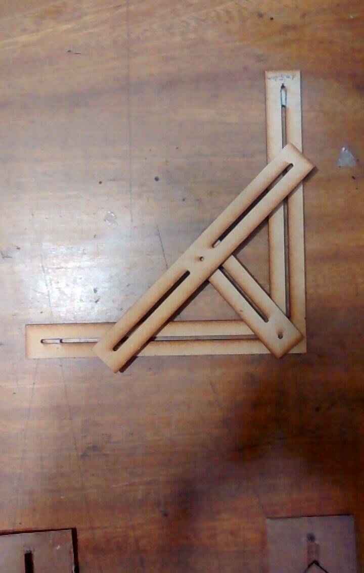
3rd Scott Russel Model: One of the holes of the short lined piece is at half of the large lined piece's length (Made at HOME)
9. I finished my cartboard design.
10. Although, now I was able to clearly design my idea in my computer, the process of using cartboard took a lot of time. Therefore, I decided to design my machine in Inventor (because of recommendations by Fabbers) without a previous testing of other software.
11. I designed and assembled each piece in the same order I built my machine in cartboard.
12. I opened Inventor -> clicked New -> clicked Standard (mm).ipt
13. I clicked Create 2D sketch and clicked in the centered plane.
14. I made a 208mmx248mm rectangle using the option Rectangle in the Sketch Menu
15. I clicked on Finish sketch and the design moved to diagonal position -> I clicked Extrude in the Tool Menu -> Change 10mm for 3mm -> Clicked in the rectangle surface. Thus, I had created a 3D picture.
17. I clicked on Top -> I clicked in the gray surface -> I clicked the right botton that said "Create Sketch" when you stayed more than 1 second on it ->
18.
I realized the rectangle measures should have been 206mmx246, because
the thickness of the object I was designing was 3mm. Therefore, I
inserted Ctrl+z -> I clicked on the centered button ("Edit Sketch")
and corrected the measures -> I clicked on Finish Sketch.
19. I repeated Step 17 -> I looked the Sketch bar -> I clicked on the upper botton of Project Geometry -> I clicked the surface -> The surface's borders turned yellow
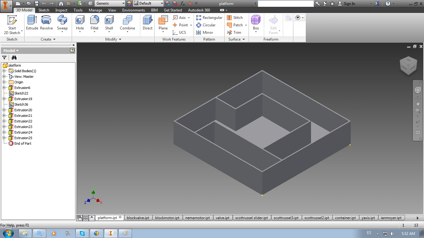
18. I used Line and Rectangle buttons to delineate the walls of the object. I started with the outer walls -> I continued with the inner walls -> I trimmed the insides of the walls (as you can see in the picture below) using Trim button.
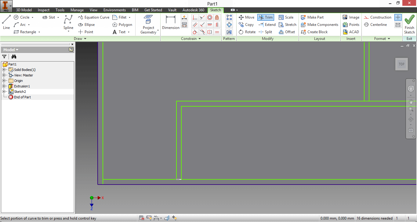
19. This is how my work ended
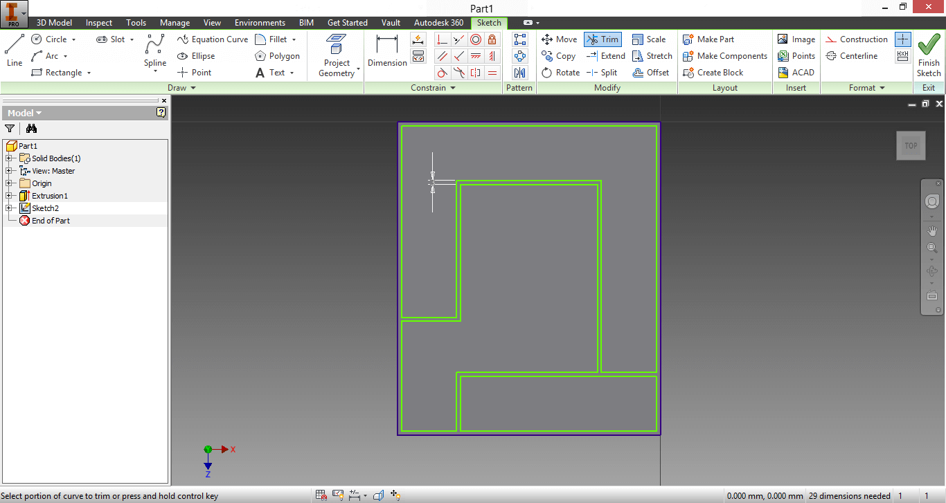
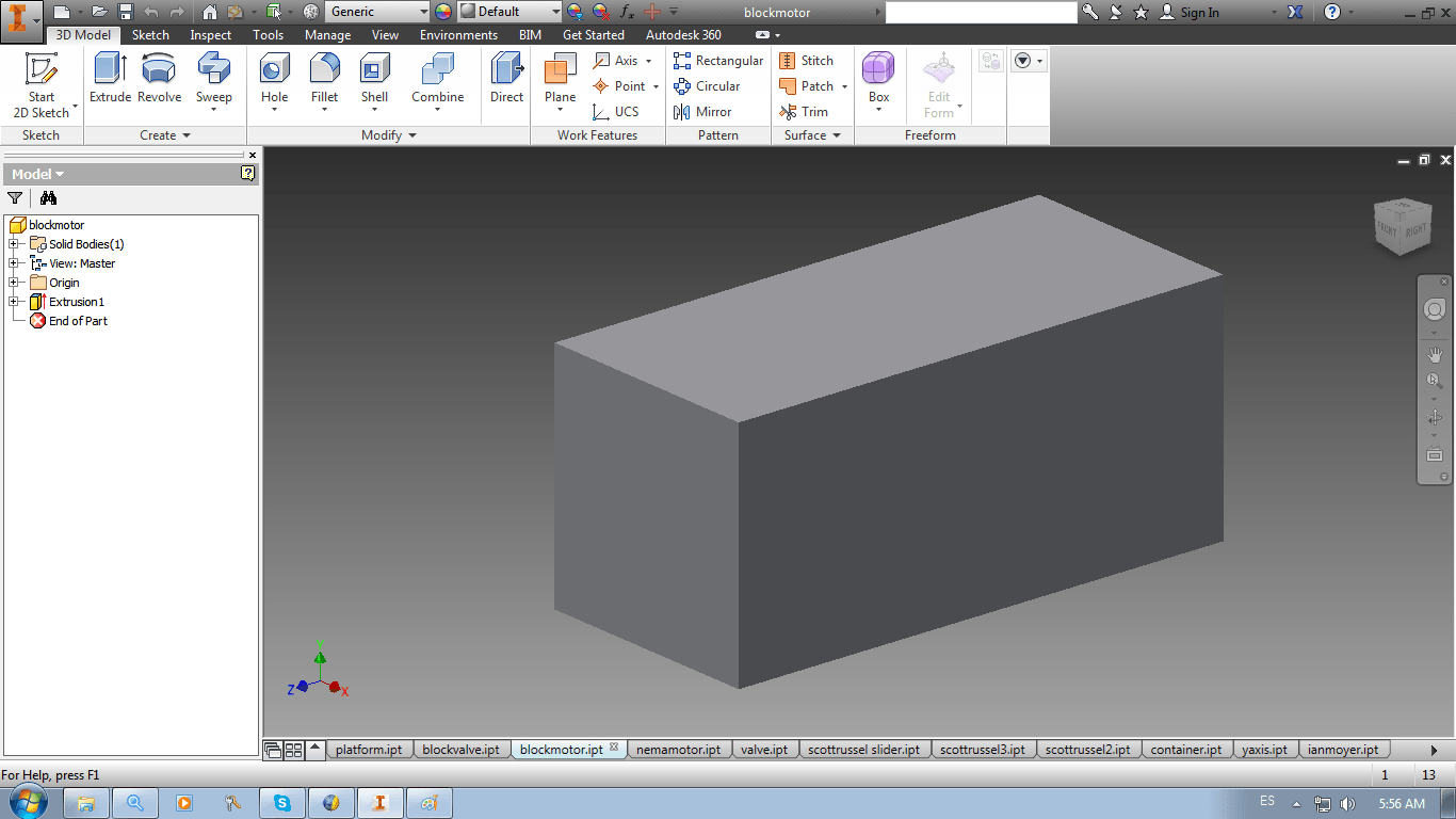
20. I extruded the walls repeating Step 15. I got my 3D picture.
PLATFORM19. I repeated Step 17 -> I looked the Sketch bar -> I clicked on the upper botton of Project Geometry -> I clicked the surface -> The surface's borders turned yellow
18. I used Line and Rectangle buttons to delineate the walls of the object. I started with the outer walls -> I continued with the inner walls -> I trimmed the insides of the walls (as you can see in the picture below) using Trim button.
19. This is how my work ended
20. I extruded the walls repeating Step 15. I got my 3D picture.
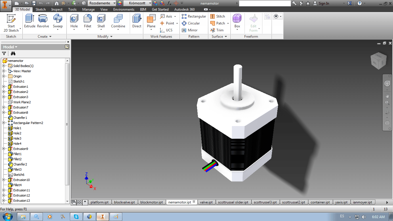
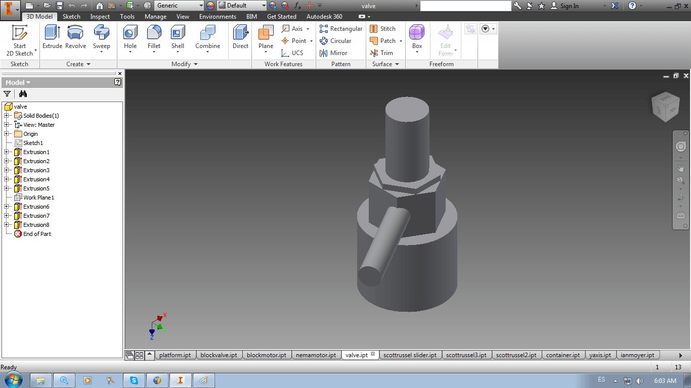
21. I repeated the same Process for
the rest of the pieces, but using more figures and working with
different degrees of complexity
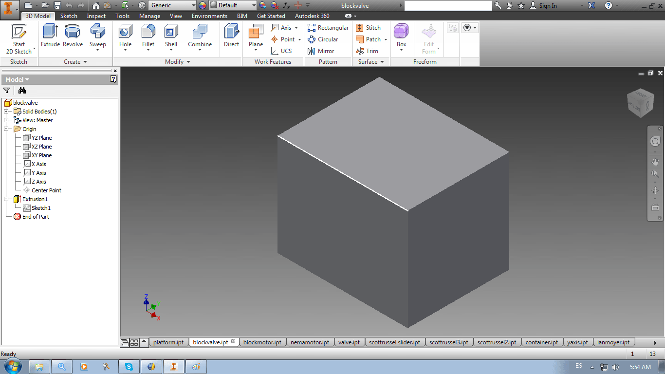
BLOCK FACING VALVE
BLOCK FACING MOTOR
NEMA MOTOR (DOWNLOADED)
VALVE
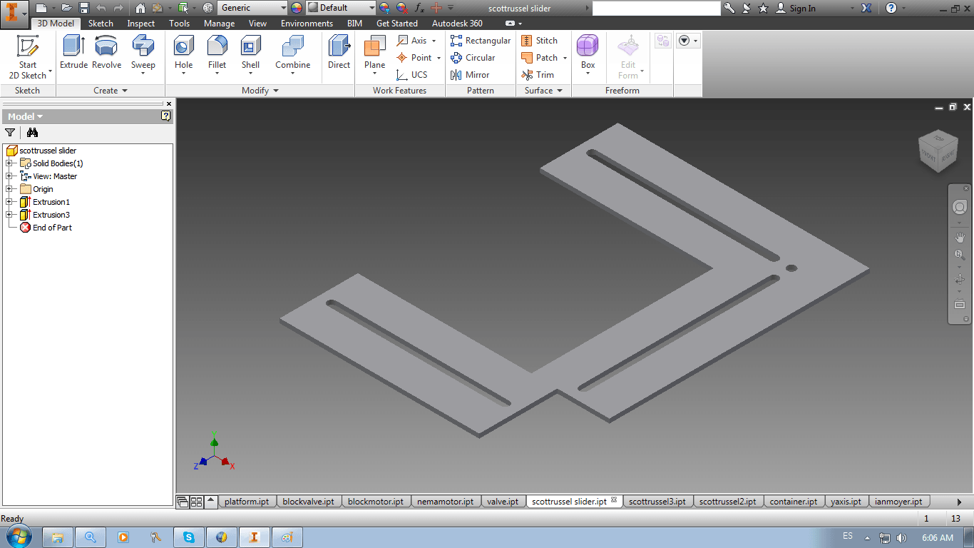
SCOTT RUSSEL SLIDER
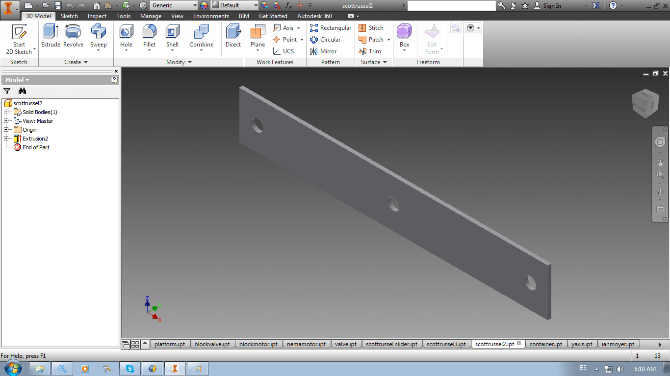
SCOTT RUSSEL PIECE 2
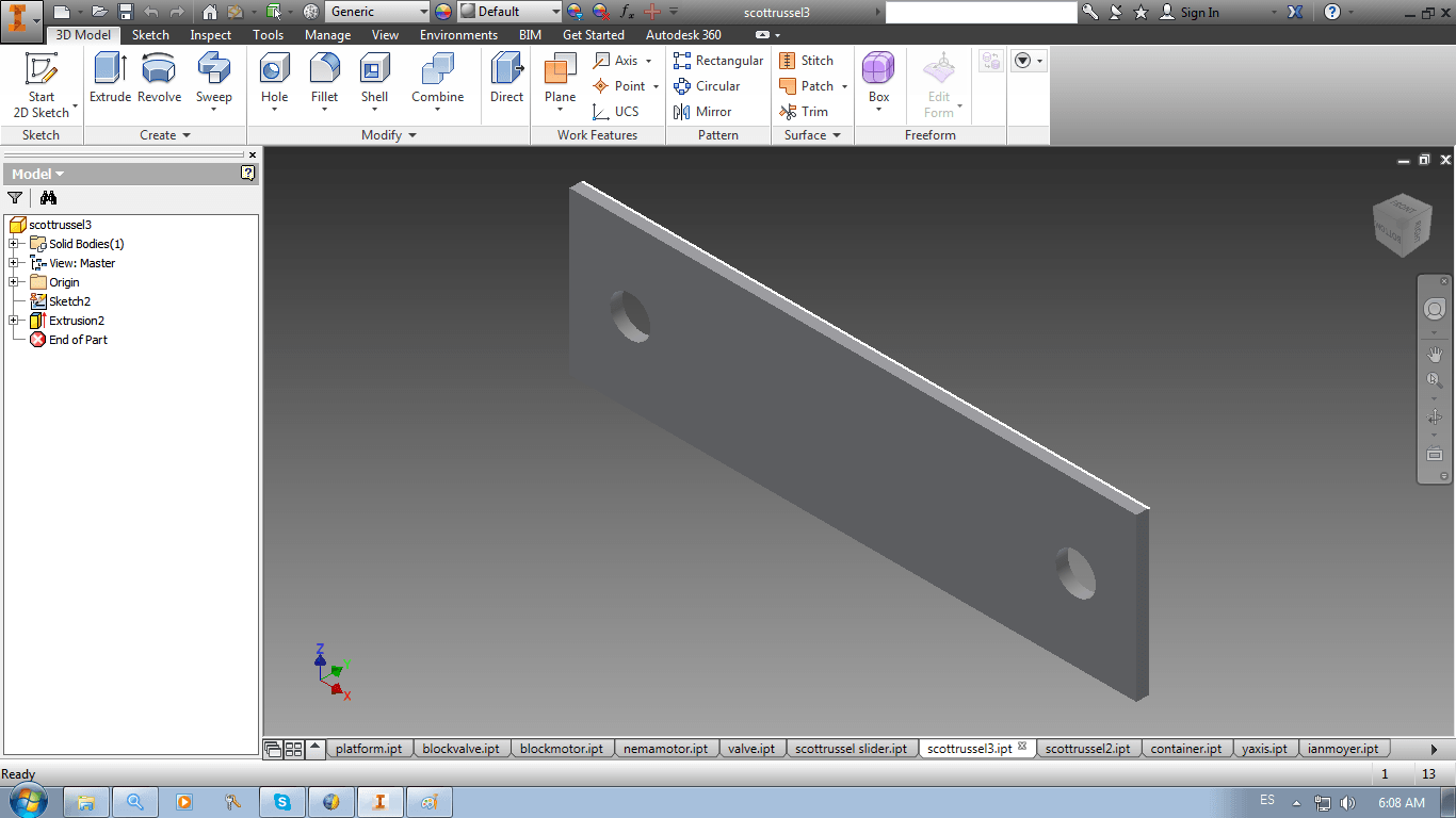
SCOTT RUSSEL PIECE 3
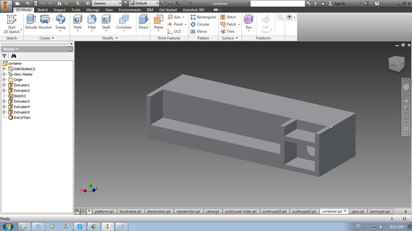
CONTAINER
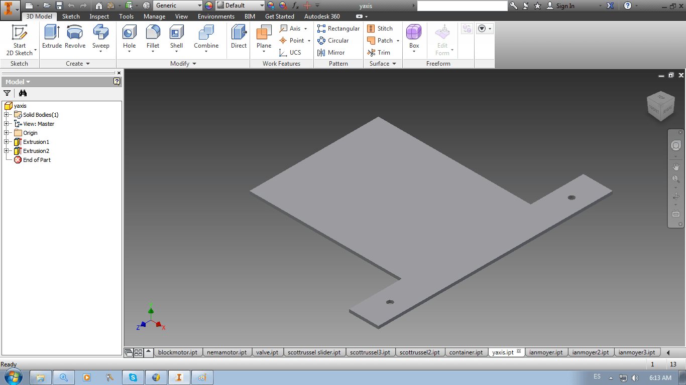
Y AXIS SLIDER
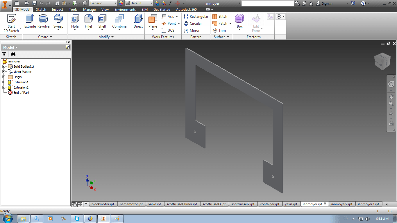
IAN MOYER PIECE 1
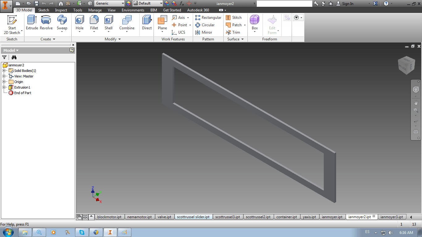
IAN MOYER PIECE 2
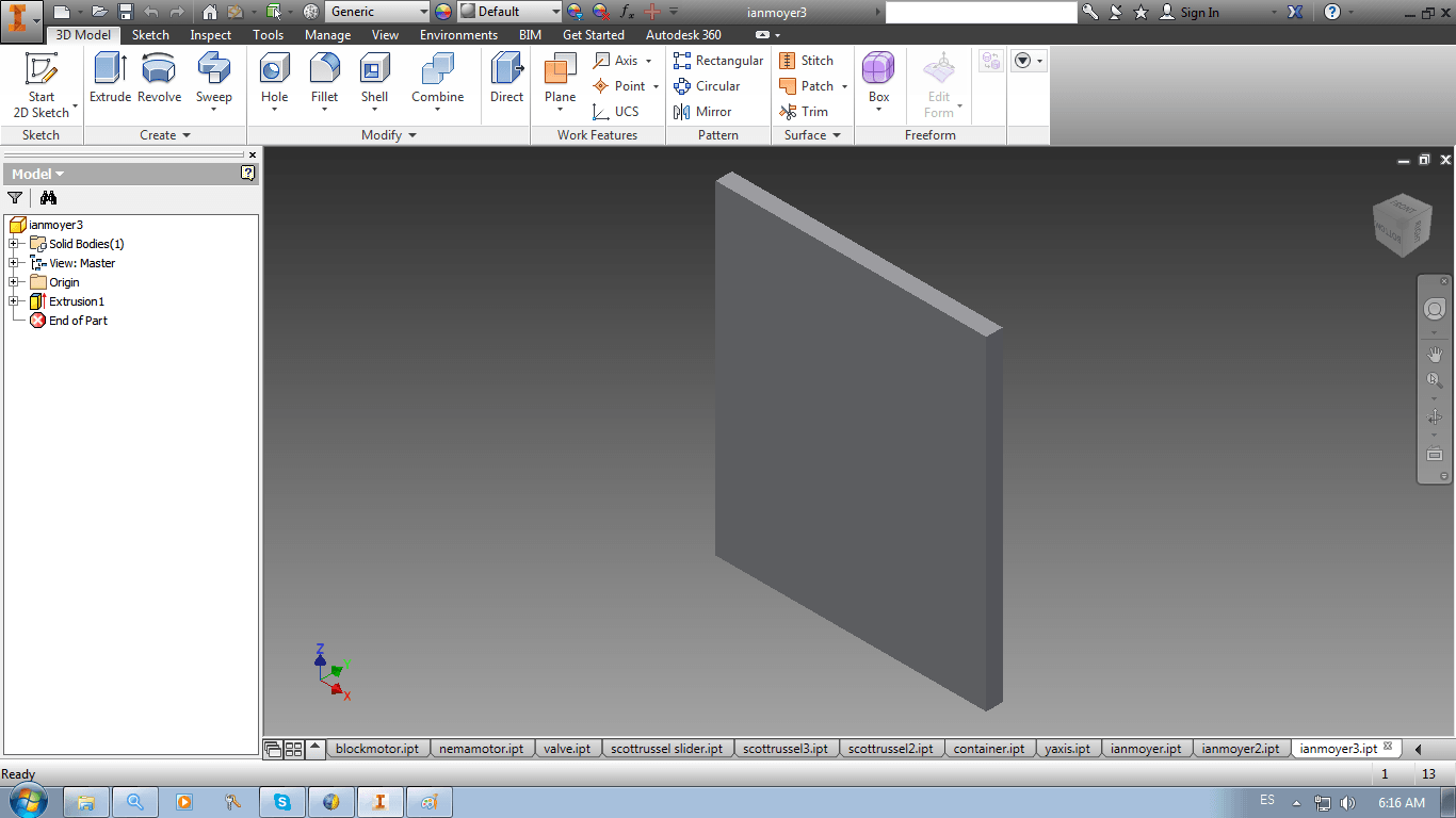
IAN MOYER PIECE 3
NEMA MOTOR (DOWNLOADED)
VALVE
SCOTT RUSSEL SLIDER
SCOTT RUSSEL PIECE 2
SCOTT RUSSEL PIECE 3
CONTAINER
Y AXIS SLIDER
IAN MOYER PIECE 1
IAN MOYER PIECE 2
IAN MOYER PIECE 3
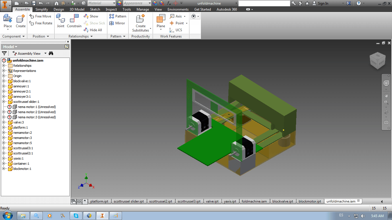
ASSEMBLY 1: UNFOLDED MACHINE
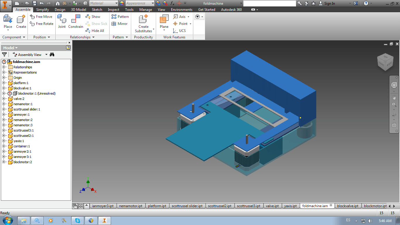
ASSEMBLY 2: FOLDED MACHINE
You can download my Asssemby of the foldable machine here and the unfoldable machine here.
12. I just designed the container in Rhinoceros.
13. Last, I compared the two softwares (look below)
1. Inventor is more intuitive than Rhinoceros, as it does not need to use options such as "Difference" to make holes.
2. Inventor uses constraints, which makes it hard to erase mistakes. On the other hand, Rhinoceros does not uses constraints.
3. Inventor allows to assemble pieces more precisely and easily.
-> Inventor Wins! 2-1
14. For being honest, I lost my Rhinoceros file and I am not very fluent in it. I decided to experiment with another software that would allow me to approach design through an intuitevely way: I designed in SketchUp. Here you can download my design.
15. First, I opened SketchUp after selecting the Millimeters option
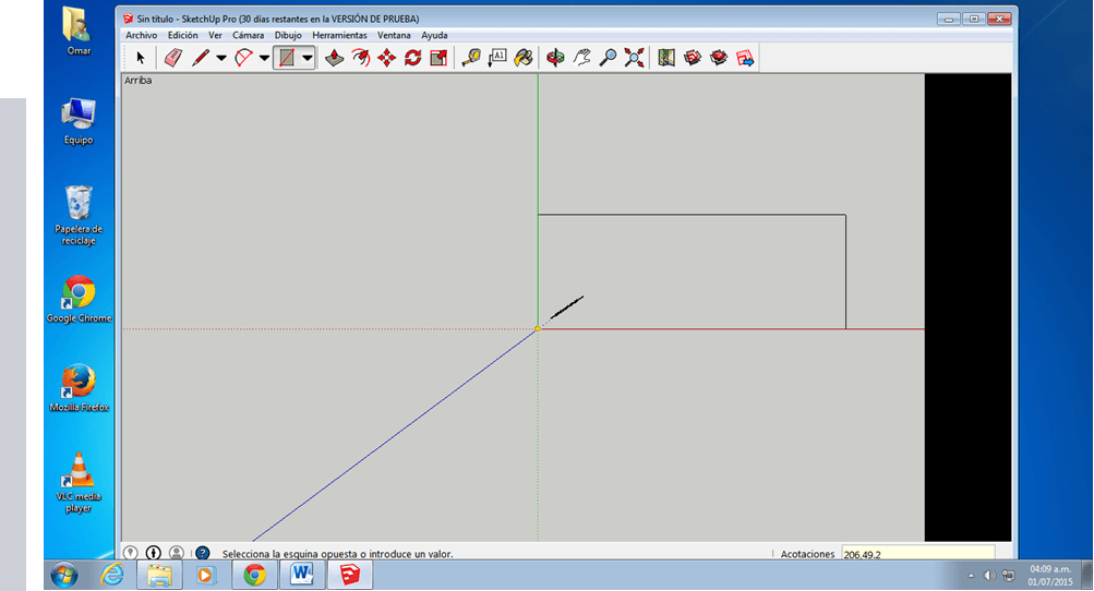
16. I chose Rectangle option and wrote '206,49.2', the parameters of my container
17. Clicked on Camera -> Clicked on Standard Windows -> Clicked on Top -> Clicked on the rectangle with the arrow -> Wrote 43.2
18. Clicked on Camera -> Clicked on Standard Windows -> Clicked on Frontal -> Clicked on the Pencil button-> Make inner walls of the container -> Clicked on Isometric
19. Clicked on Circle -> Make a Circle inside the Container
20. Clicked on the rectangle with the arrow -> Extrude circle until reaching the wall
Last, I compared the previous winner with SketchUp (look below)
1. Both softwares are very intuitive. I did not have to use any Difference command for substracting extrusions in any of the softwares.
2. Inventor uses constraints, which makes it hard to erase mistakes. On the other hand, SketchUp does not uses constraints.
3. Inventor allows to assemble pieces more precisely and easily.
-> Tie, I think that both softwares are very useful, but Inventor should be used for detailed and complex staff while SketchUp should be used for simple things that can be done in less time.
OBSERVATIONS
1. The hinges of the foldable Ian Moyer pieces are not shown
2. The hinges of the foldable Y-axis slider are not shown
3. The screws that connect most of the pieces are missing
4. Another Scott Russel Mechanism for enlarging the 3D Scanning zone is missing
5. As the surface of the machine has a slider and a mechanism (not a plain surface), a way of completely folding the machine needs to still be figured out
6. The pulleys of the Ian Moyer's mechanism are not shown