STEP 16: MECHANICAL DESIGN
OBJECTIVE
- Automate a machine
- Document group and individual project
FOUR PARTS
1. Downloading & Understanding files
1.1. Hardware
1.2. Software (Programming Gestalts)
2. Electronics
3. Electricity and Power
4. Testing Machine
BACKGROUND & INSPIRATION
- Nadya Peek's FoamCutter
1. DOWNLOADING AND UNDERSTANDING FILES
1.1. HARDWARE
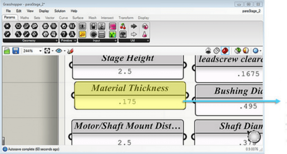
1) As we are working with Grasshopper, is essential to change the Material thickness to adapt the inspiration design to our own Fab Lab conditions
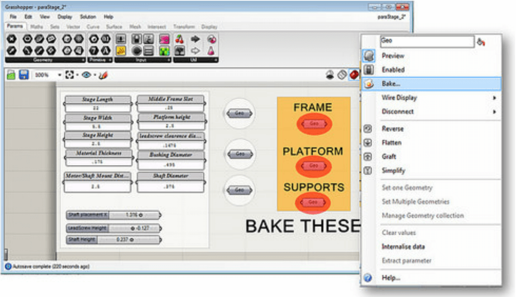
2) However, we need to 'Bake' the changes if we want to visualize them. What does 'Bake' means? It means "Apply". Thus, we right click each GEO -> Click Bake
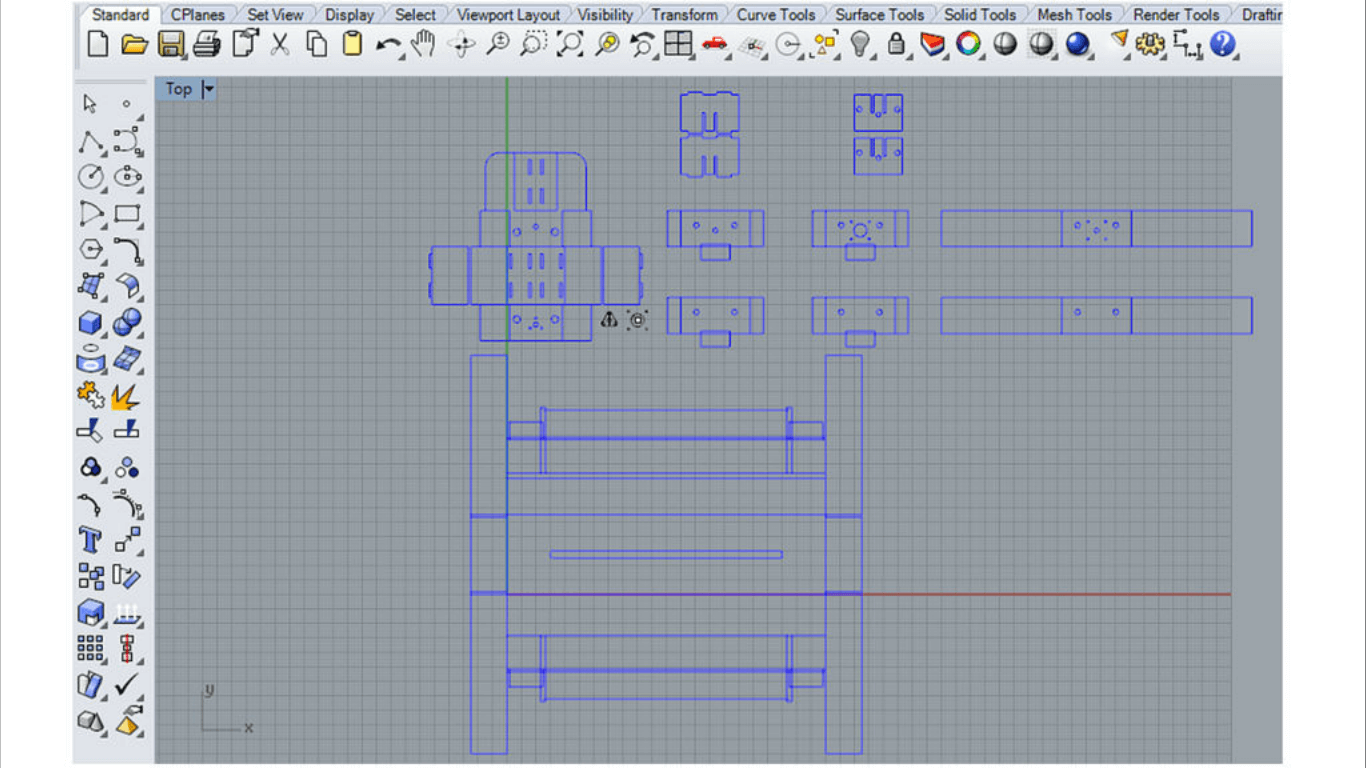
3) Below are the lines with new thickness
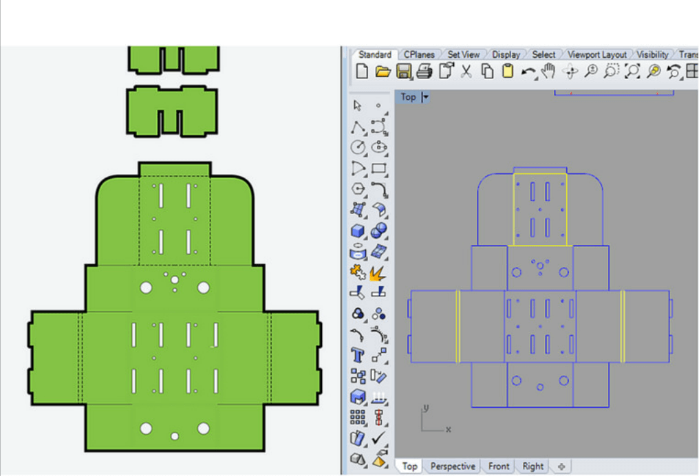
4) After the transformation, some the image features are lost; therefore, it is necessary to use the previous image a reference to identify which lines are cut and which ones are folded. Now, the file can be cut.
Note: By analyzing the reference, is how we noticed that two pieces were missing.
5) Below are the final folded pictures.
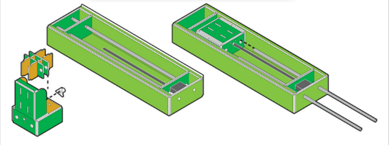
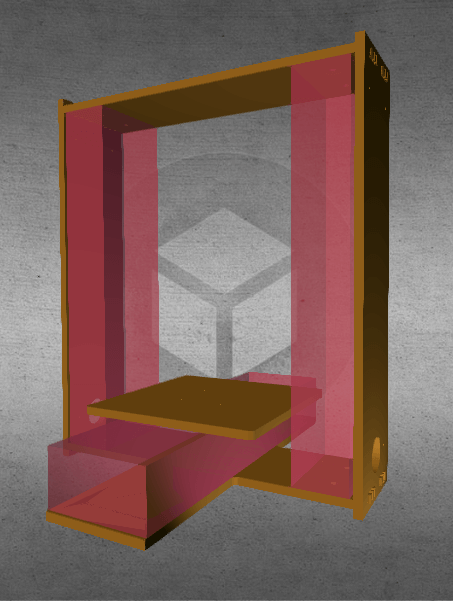
6) Now, we can infer how the hardware mechanism works: X and Z move
7) A wooden stand created by the Fab TECSUP team just by using press-fit.
8)
Apart from helping in carrying material and cutting it, I was in charge
of the synthetizing each part for the final presentation due to my
fluency in English. This what I said about the Hardware part:
A machine for cutting foam through y and z directions, has been devoloped using micron wire as the cutter ultimate tool. Cases that surrounded each of the stepper motors were build out of 4mm corrugated cartboard using the laser cutter. A porch that supports that whole structure, fabricated in the Shopbot, was build using 14mm phenolic board. Press-fit unions were used for joining the structure's pieces.
1.2. SOFTWARE
1) We downloaded Peek's and Moyer's files -> Installed pygestalt-master
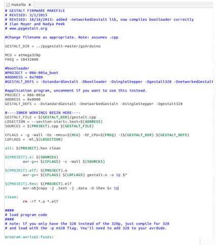
2) Programs were recorded with the Makefile in application mode on the node cards.
3) gestalt.cpp and 086-005a.cpp were the files that were recorded in the node cards through sudo make -f Makefile program-avtisp2 command
4) We run Nadya's example xy_plotter.py with python.
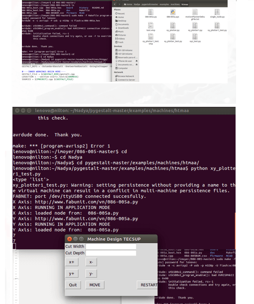
5) The buttons in the interphase allows the user to insert data that will let the machine move in different rectinlinear directions.
2. Electronics
1) First, we need to understand how the Gestalt works!
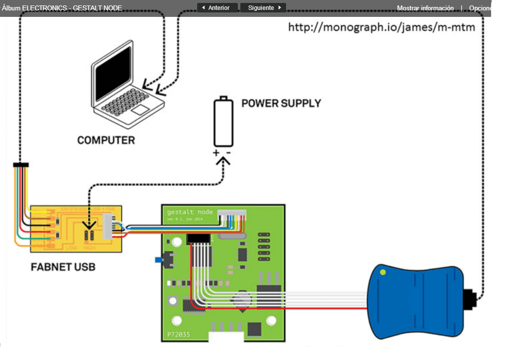
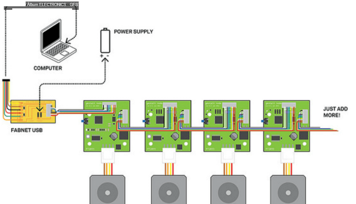
- What I learned from this part of the project and later presented in June 26th was that the 2 Gestalt boards were used in similar and different ways. The first one controlled a stepper motor that moved through the y axis direction, while the second board controlled two synchronized parallel stepper motors that also move, but had the same output pins as their cables were solded together. Also, node cards are used to control the motors besides the Fabnet.
- It should be mentioned that there are two groups of coils inside of each stepper motor and there is a pair of cables for each of the six coils.
3. Electricity and Power
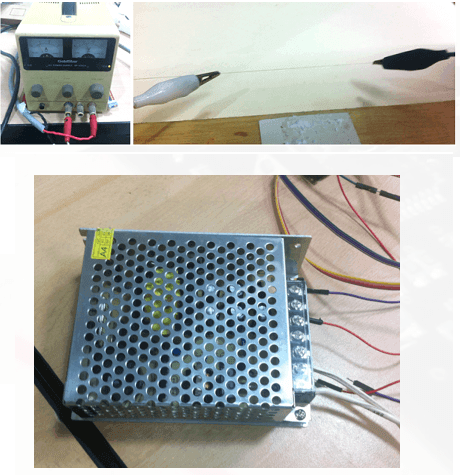
- The power supply feeds the 12Vdc micron
- 3A is in charge of cutting the Styrofoam
- A 4A 12Vdc source is used to power the stepper motors.
-
The use of the 2 sources 12 volts that enter the system can be best
divided into two categories: force and control. The first type is
identified when the stepper motors move and the second type can be
illustrated when the central region of the micron is heated by power
source for executing the foam cutting
The pictures and videos presented in this assignment are in the link Machine Design and has been prepared and edited by Claudia Aguilar to document the work of the group. Thank you.
4. TESTING
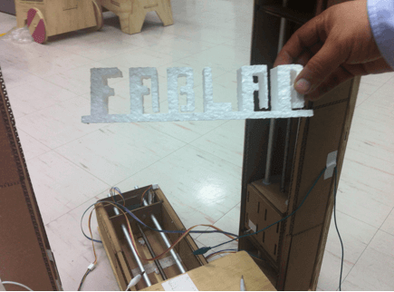
- You can watch it work here.
- Automate a machine
- Document group and individual project
FOUR PARTS
1. Downloading & Understanding files
1.1. Hardware
1.2. Software (Programming Gestalts)
2. Electronics
3. Electricity and Power
4. Testing Machine
BACKGROUND & INSPIRATION
- Nadya Peek's FoamCutter
1. DOWNLOADING AND UNDERSTANDING FILES
1.1. HARDWARE
1) As we are working with Grasshopper, is essential to change the Material thickness to adapt the inspiration design to our own Fab Lab conditions
2) However, we need to 'Bake' the changes if we want to visualize them. What does 'Bake' means? It means "Apply". Thus, we right click each GEO -> Click Bake
3) Below are the lines with new thickness
4) After the transformation, some the image features are lost; therefore, it is necessary to use the previous image a reference to identify which lines are cut and which ones are folded. Now, the file can be cut.
Note: By analyzing the reference, is how we noticed that two pieces were missing.
5) Below are the final folded pictures.
6) Now, we can infer how the hardware mechanism works: X and Z move
7) A wooden stand created by the Fab TECSUP team just by using press-fit.
A machine for cutting foam through y and z directions, has been devoloped using micron wire as the cutter ultimate tool. Cases that surrounded each of the stepper motors were build out of 4mm corrugated cartboard using the laser cutter. A porch that supports that whole structure, fabricated in the Shopbot, was build using 14mm phenolic board. Press-fit unions were used for joining the structure's pieces.
1.2. SOFTWARE
1) We downloaded Peek's and Moyer's files -> Installed pygestalt-master
2) Programs were recorded with the Makefile in application mode on the node cards.
3) gestalt.cpp and 086-005a.cpp were the files that were recorded in the node cards through sudo make -f Makefile program-avtisp2 command
4) We run Nadya's example xy_plotter.py with python.
5) The buttons in the interphase allows the user to insert data that will let the machine move in different rectinlinear directions.
2. Electronics
1) First, we need to understand how the Gestalt works!
- What I learned from this part of the project and later presented in June 26th was that the 2 Gestalt boards were used in similar and different ways. The first one controlled a stepper motor that moved through the y axis direction, while the second board controlled two synchronized parallel stepper motors that also move, but had the same output pins as their cables were solded together. Also, node cards are used to control the motors besides the Fabnet.
- It should be mentioned that there are two groups of coils inside of each stepper motor and there is a pair of cables for each of the six coils.
3. Electricity and Power
- The power supply feeds the 12Vdc micron
- 3A is in charge of cutting the Styrofoam
- A 4A 12Vdc source is used to power the stepper motors.
The pictures and videos presented in this assignment are in the link Machine Design and has been prepared and edited by Claudia Aguilar to document the work of the group. Thank you.
4. TESTING
- You can watch it work here.