Week 11: Output Devices
4.15.2015 - 4.21.2015
Lecture Notes:
Homework:
- Add and program an output device to a micro-controller board
Resources:
Files:
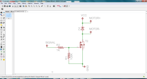
- Eagle Schematic,
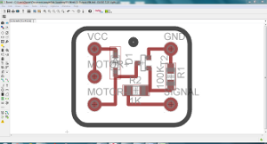
Board
- Trace Image, Perimeter Image
Acknowledgements:
Many thanks to Andrew Harmon for his guidance on this project.Project:
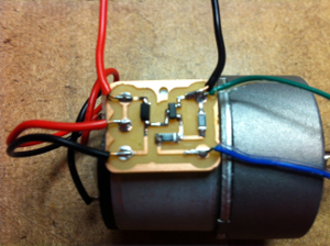
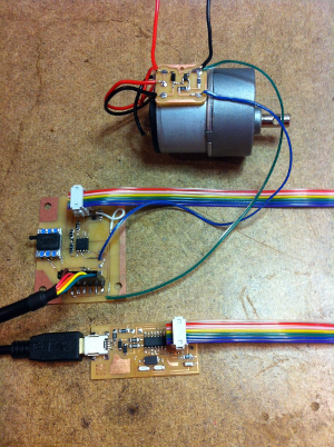
For this project I constructed a N-type MOSFET circuit to switch higher output voltages and currents than capable of the ATtiny 45. in this case the MOSFET was used to operate a gear motor.Design & Fabrication:
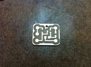
The MOSFET board was designed in Eagle and included a series
resistor on the gate lead and a second 100K parallel resistor
from the gate to ground. The 100K resistor acted to remove
electric charge between the gate and source leads and turn off
the MOSFET. A Shotkey diode was placed in parallel with
the output pads to ensure no induced backwards current from the
DC gear motor's windings found its way to the MOSFET when
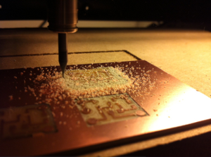
shutting off the motor. The board was exported as a high
resolution PNG from Eagle and milled using the Fab Modules on
the Roland MDX-20 milling machine. The process was similar
to that described for Week 4
Electronics Production.
 |
 |
 |
 |
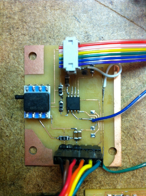
I recycled the vacuum sensor input board from week 10 and,
after removing the LED and current-limiting resistor output,
wired the MOSFET board as its new output device. Power to
the MOSFET board was supplied by an external variable power
supply. The MOSFET's ground was connected to the sensor
board and its gate to pin PB3.
The MOSFET used in this board has a maximum drain-source
voltage of 30V and maximum current of 1.7A with power
dissipation of 0.5W.
Energizing the MOSFET's gate with the ATtiny 45 from the sensor
board, I switched voltages up to ___V but not before damaging a
couple of diodes installed backwards.
 |
 |
 |