Week 4: Electronics Production
2.18.2015 - 2.24.2015
Lecture Notes:
Homework:
- Mill the FabISP in-circuit programmer circuit using the Fab
Modules and FR1 material
- Stuff the board with surface mount components (see fab
inventory)
Resources:
- Fab
Academy Handbook
- Fab Modules (fabmodules.org)
- Fab Modules Downloads, Guide, Tutorials (downloads)
Files:
- FabISP Traces (hello.ISP.44.traces.png)
- FabISP Perimeter (hello.ISP.44.res.interior.png)
Acknowledgements:
Many thanks to Andrew Harmon for his advice and assistance
during this project. I also wish to thank Dave Ross and
Terence Fagan for their assistance troubleshooting my software
questions.
Software Installation & Setup:
Fab Module installation through Ubuntu followed the steps
below:
- Ubuntu was updated prior to beginning installation.
This step was unique to the desktop computer used for this
project.
- All Fab Modules were downloaded through the
kokompe.cba.mit.edu page
- Dependencies were installed through the Ubuntu terminal with the command: sudo apt-get install python python-wxgtk2.8 python-dev python-pip gcc g++ libpng12-dev libgif-dev make bash okular libboost-thread-dev libboost-system-dev cmake
- Compiling and copying all executables was performed according to the instructions within kokompe.cba.mit.edu
- Fab Lab Tulsa's MDX-20 is normally configured to use a
serial cable from a Windows OS to mill. This cable was
disconnected in order to communicate via the Fab Modules over
a USB-Serial cable in Ubuntu.
MDX-20 Setup & Operation:
- I used 25mm thick polyurethane foam beneath my board as a
sacrificial layer and initially did not surface it for the
first trail cut.
- The board was oriented with its long axis parallel to the MDX-20's y-axis to match the orientation of the png trace silhouette and secured to the foam with double-sided tape.
- The Fab Modules were launched through Ubuntu's terminal
typing fab.
- The MDX-20's front cover was removed to facilitate changing
and zeroing end mills. The front cover's metal tab was
secured in the micro switch slot on the mill's right hand side
to allow MDX-20 to operate.
- I familiarized myself with the fields within the Fab Module
UI and performed the following steps to send the milling
instructions to the MDX-20: Input Format: (image
.png) > Output Process: Roland Mill (.rml) >
Process: make_png_rml > Tool 1/64 end mill trace >
select 3D plane > adjust xmin, ymin > make path >
make rml > send.
- Default Fab Module tool settings for a 1/64 inch (0.4mm) and
1/32 (0.8mm) end mill were used to cut the traces and
perimeter respectively. Offsets were adjusted to remove
most the the copper foil in and around the traces.
- To establish the origin with respect to the board I used the
xmin and ymin fields within the Fab Module and the up and down
arrows on the MDX-20's front panel. Machining margins
were included around the traces. Zeroing the end mill in
the z direction was performed using the "drop" method of
manually lowering the end mill in a loosened collet until it
was in contact with the board's upper surface prior to
tightening the collet's two set screws.
- The first board milled was unfortunately a failure (see image below). The unevenness of the polyurethane foam was apparent as the end mill only made contact with a portion of the board while milling the traces. A 1/64 in (0.4mm) ball end mill was also mistakenly used and did not adequately remove the copper foil where it made contact with board.
- To surface the foam for a second trail I drew a black
rectangle measuring 70 mm x 100mm in Inkscape, saved it in a
.png format and loaded it into the Fab Module as was done for
the FabISP traces. I used a 0.125 in (1.6mm) square end
mill, the default Fab Module tool settings for wax rough cut,
and a 1mm cutting depth for surfacing. The bot Z (min)
was mistakenly set 10 rather than 1 and the job was aborted
after it had started another pass. The Fab Module output
was an unusual milling tool path using circular arcs and long
jogs across the length of the rectangle between passes.
- Once the foam was surfaced, I proceeded to repeat the steps above to mount a new board, load the hello.ISP.44.traces.png, zero the 1/64 in (0.4mm) square end mill, load the default tool settings, and make path>make rml>send to mill. Milling the perimeter was performed in a similar manner using a 1/32 in (0.8mm) square end mill. Success!
- I subsequently milled two additional spare boards.
Soldering:
- Refer to the board layout diagram here
- Prior to soldering I deburred the board using an dry
abrasive pad and dusted the surface to remove any particles.
- Using a temperature-controlled soldering iron (345C), liquid
flux, tweezers, copper braid, and a magnifying light I began
stuffing the board with components from the center outwards
starting with the smaller parts first.
- The flux was extremely helpful wetting the trace's and
controlling how much solder I used. Resting the board on
a table and pinning the loose components one at a time to
their pads with a pair of tweezers gave me the most control
soldering.
- At least one component was desoldered using Andrew's help
and two soldering irons to remove it and reposition it.
Excessive solder was not an issue and the original drops were
reheated in place.
- Following soldering, the board was visually checked for bridges and then washed and scrubbed alternately with water and 90% isopropyl alcohol. The particular flux used for this project is known to leave a conductive residue. A multimeter used to test for shorts across a selection of points on the board to verify the flux was adequately removed.
Figure 1. Milling Workstation
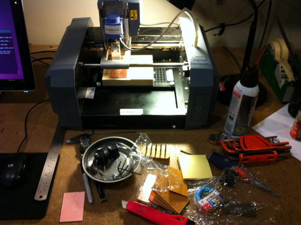
Figure 2. Zeroing End Mill along Z Axis
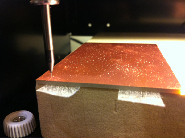
Figure 3. Milled Circuit Board with Skewed Substrate

Figure 4. Leveling Polyurethane Foam Substrate
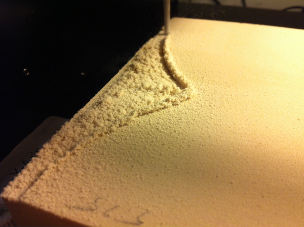
Figure 5. Fab Module UI Output - Surfacing
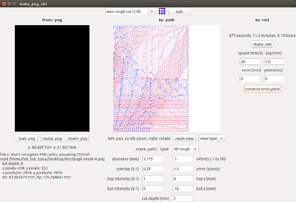
Figure 6. Fab Module UI Output - Milling Traces
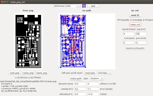
Figure 7. Milling Circuit Board
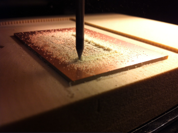
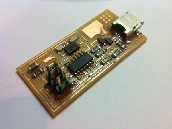
Figure 8. Milled Circuit Board
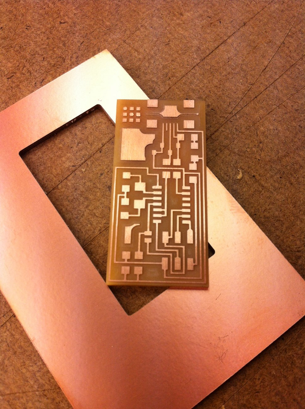
Figure 9. Stuffed Circuit Board (FabISP in-circuit programmer)