Final Project: Modular Vacuum Former
6.24.2015
Lecture Notes:
Homework:
- Design, fabricate, and document a final project that
encompasses topics from earlier assignments
Resources:
Files:
- Structure: DXF 1, DXF 2
- Grates: SVG 1, SVG 2, PDF 1,
PDF 2
- Check Valve: Valve IPT 1, Valve IPT 2, Valve STL 1, Valve STL 2, Reed SVG, Reed PDF
- Control board: Eagle SCH
/ BRD, Trace PNG, Perimeter PNG
- Programming: Arduino INO
- Machining Parameters
- BOM
Acknowledgements:
Many thanks to Andrew Harmon for his advice, troubleshooting, and assistance with this project. Thanks to Brandi, Angela, and Dennis for their assistance during assembly and testing.Project:
My final project consists of a proof of concept modular vacuum former system (MVFS) that uses a sealed medium density fiberboard (MDF) structure, programmable infrared heating system, and a sliding frame to heat and rapidly form thin plastic parts. Each vacuum former module includes check valves and latches on either end so multiple modules can be joined together via their vacuum tables and create a larger forming area. By joining modules, a single vacuum motor could potentially draw air from multiple tables as opposed to using multiple motors.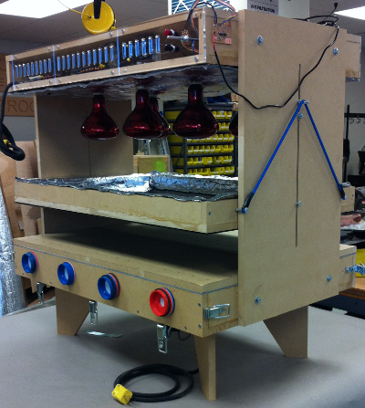
Structure:
The structure of the vacuum former was milled from 0.75 inch
(19 mm) medium-density fiberboard (MDF) using a Shopbot PRS
Alpha 96 3-axis milling machine with a 0.25 inch (6.35 mm)
square end mill. The structure consisted of four principal
pieces: 1) vacuum table, 2) bulb/electronics enclosure, 3)
frame, and 4) frame rails.
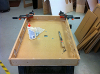
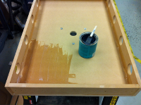
After assembling the vacuum table's lower enclosure with glue
and fasteners, its inner surface (including edges around its
valve ports and vacuum motor port) was sealed with wood
sealer. Foam strips and sheets were used as temporary
seals between the vacuum table's bed and its lower enclosure,
between the vacuum motor's housing and the vacuum table's
underside, as well as around the eight check valves. The
vacuum motor was installed in the center of the vacuum table's
lower surface by compressing its housing between an MDF plate
and razor-cut foam gasket.
 |
 |
 |
 |
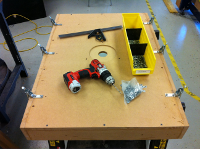
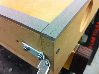
Draw latches were fastened to the front and rear ends of the vacuum table to join additional vacuum former modules, compress and seal gaskets around the valves, and increase the forming area. Blocking was glued to the underside of the vacuum table's bed prior to fastening it to the lower enclosure to resist large deflections under reduced internal air pressure.
 |
 |
 |
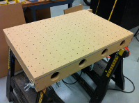 |
The vacuum table was elevated on four MDF legs fastened through the its lower surface.
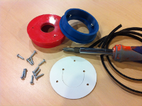
Check Valves:
Eight reversible check valves were designed to fill the ports
on either end of the vacuum table. The valve bodies were
designed in AutoDesk Inventor and constructed of two FDM
3D-printed Acrylonitrile Butadiene Styrene (ABS) valve halves
fastened together with screws.
The valve halves were printed using a MakerBot Replicator 2X
with two different filament colors to facilitate identifying the
direction of air flow through the valve. Valve halves were
drawn and printed using the nominal port inner diameter
dimensions. Actual valve body outer diameters exhibited a
-0.010 to +0.05 inch (-0.25mm to +0.13mm) tolerance and were
somewhat oval.
The valve's sheet metal screws tapped their own threads through
undersized 3D printed pilot holes.
 |
 |
 |
 |
The printed valve halves would benefit from additional infill
(greater than 10%) to address irregular surfaces particularly
evident in the red parts.
The valves were positioned in their ports with flanges and
sealed with foam gaskets (one on either side of the
flange). The natural gum foam selected for the gaskets
proved to be unsuitable for laser cutting and disintegrated into
ash when heated. The foam sheets were ultimately cut with
a paper cutter into square cross-sectioned strips and adhered to
the valve bodies using rubber cement.
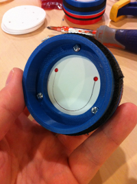
Laser cut polystyrene sheet 0.030 inches (0.76 mm) thick was
used as the reed within each check valve. The
reed consisted of a U shaped flap terminated with two circular
holes to relieve stress concentrations. The flap rests
against the smaller of the two orifices within the assembled
valve body to create a seal. In this case, the valve will
permit air flow in the direction of the blue half of the valve
pictured above while preventing flow towards the valve's red
half.
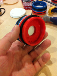
For a single standalone vacuum former module, the valves would
be inserted with their blue half (larger orifice) facing outward
to seal the vacuum table. To expand the vacuum former, the
valves would be flipped with their red half (smaller orifice)
facing outward and an additional module joined to the vacuum
former using the draw latches.
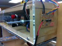
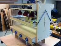
Heating / Electrical:
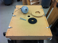
I selected common threaded infrared bulbs as the heat source for the vacuum former for ease of installation, ease of modification, widespread availability, affordability, and importantly safety. The bulbs were threaded into ceramic sockets and supported and distributed above the vacuum table in an MDF enclosure.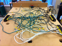 |
 |
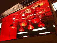 |
I wired eight sockets in parallel using terminal blocks and clustered them near the center of the enclosure. The bulbs were powered through a 3-32VDC / 25A-120VAC solid state relay (SSR) triggered by the vacuum former's control board. An additional 20A SPST switch was placed in series with the SSR to provide the operator with a manual safety interlock. Additional socket holes would permit the bulbs to be redistributed in wider patterns in the event modules are joined together.
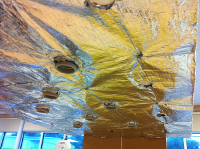
The underside of the electrical enclosure was covered in a layer of aluminized synthetic felt to further insulate it from the heat of the bulbs and reflect radiation downwards.
Laser cut and slotted cast acrylic grates covered the ends of the electronics enclosure while providing ventilation to the SSR mounted to a salvaged aluminum heat sink. Laser cut holes were also created for the switches and the potentiometer.
During operation, the IR bulbs and vacuum motor were powered from separate 20A/120VAC circuits.
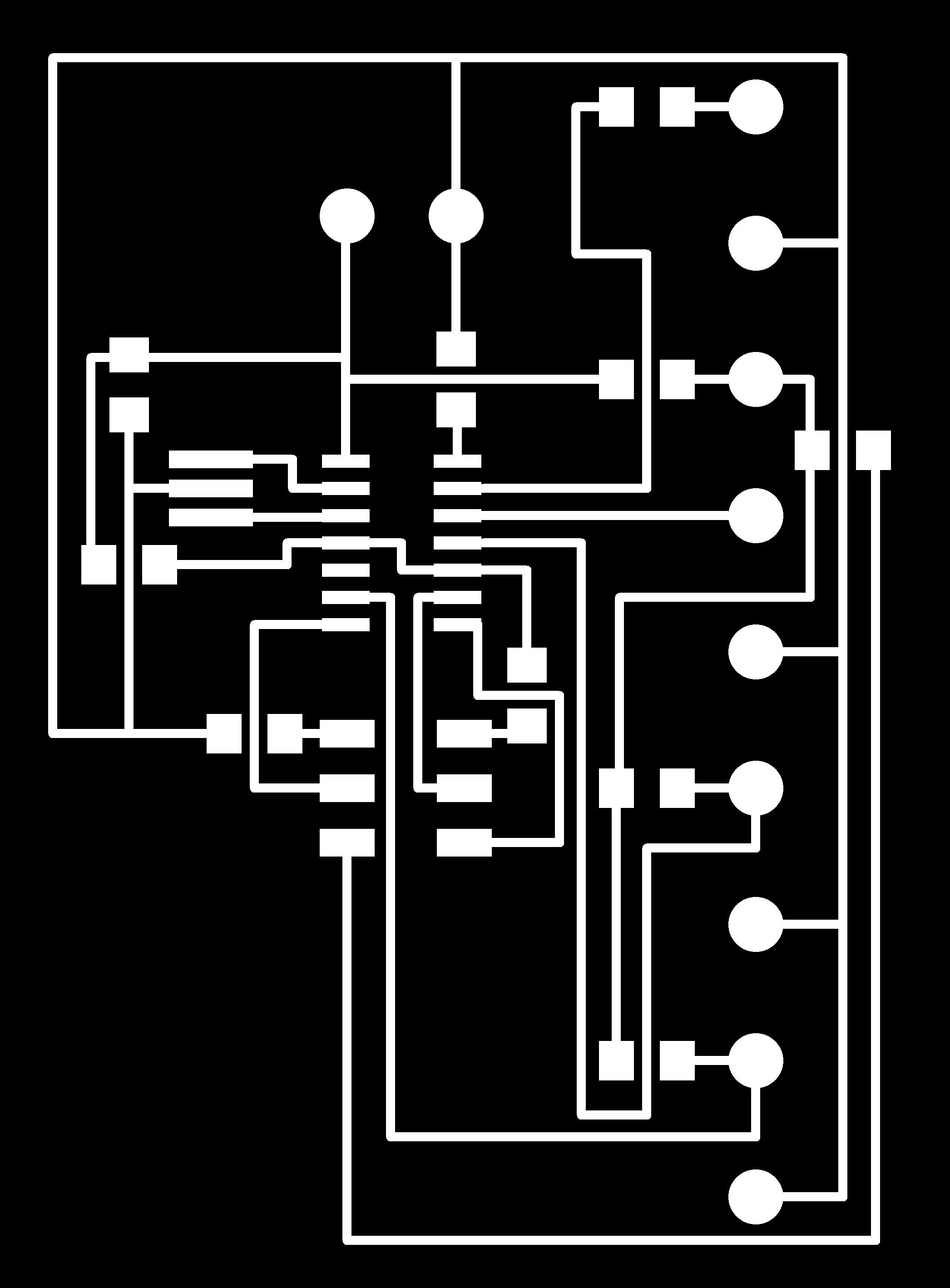
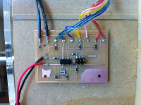
Control / Programming:
The MVF's control board used an ATMel ATTiny 44 micro-controller. Besides signals from the fabISP, micro-controller inputs included: a momentary "on" switch, a momentary "off" switch, and a 5KOhm potentiometer. Heating of the plastic was controlled by regulating the time interval the bulbs were fully energized. By adjusting the potentiometer, the operator could heat the plastic for longer or shorter intervals.
Timing was regulated by an external 20MHz resonator.
Outputs were limited to a single voltage to trigger the solid
state relay.
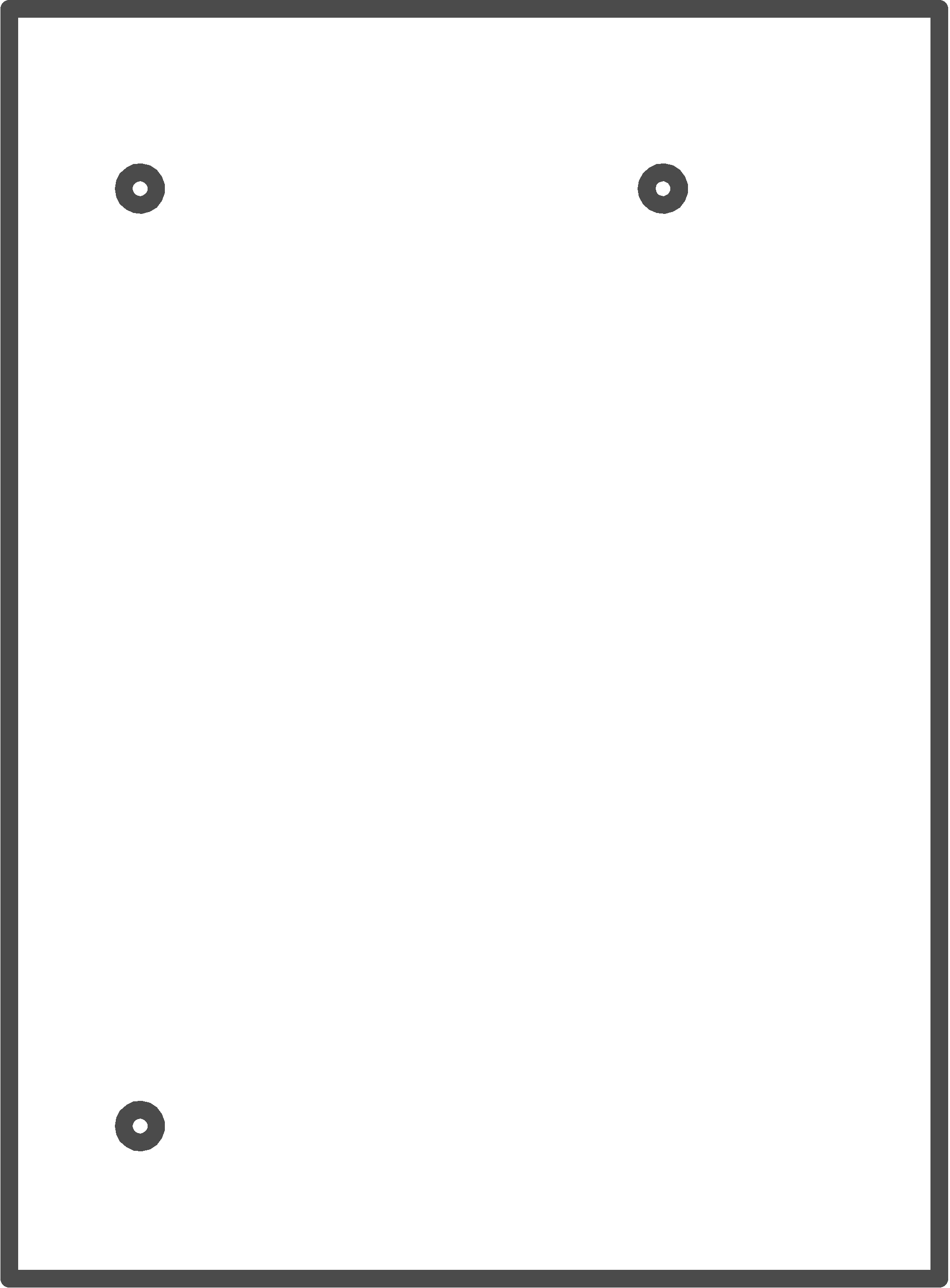
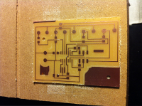
The board was designed in Eagle and milled using the Fab
Modules. Solder pads were used for many of the input and
output signals rather than headers and sockets so that
dissimilar wire gauges could be used. Board power was
supplied from a fixed 5V AC/DC power supply.
 |
 |
 |
 |
The micro-controller was programmed through the fabISP using an
Arduino sketch. The sketch was triggered by the momentary
"on" switch and then read the potentiometer's output. An
if-for statement then incrementally added an integer of 1 from
zero to the digital value equivalent to the potentiometer's
output and delayed the sketch one instance for each addition an
interval equal to a user-defined scale factor. The sketch
had the effect of turning on the bulb array for a time interval
equal to the product of the potentiometer's output and a scale
factor in units of milliseconds.
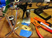
The sketch and board were successfully tested with an LED prior
to installing the board with the SSR and IR bulbs. The
1KOhm pull-up resistor on the board's relay output was found to
limit the current below that which was necessary to trigger the
SSR. Substituting the 1KOhm resistor with a 100 Ohm
corrected this issue.
A logarithmic audio potentiometer was mistakenly used instead
of a linear output potentiometer which increased the sensitivity
of the time delay to the potentiometer's rotation.
Substituting a linear output potentiometer would correct this
issue.
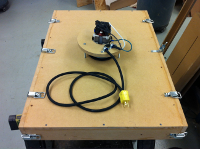
The control board was externally mounted on the electronics
enclosure for the purposes of testing but would be mounted
internally otherwise.
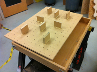
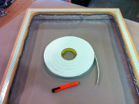
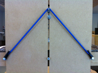
Frame:
A rigid, vertically-adjustable, single piece MDF frame was used
to suspend the plastic sheets above the vacuum table and beneath
the IR bulbs while heating. Double-sided foam tape was
adhered to the underside of the frame to hold the plastic sheets
to be formed. The tape provided a simple, low profile, and
reusable means to hold the plastic sheets and would be
periodically replaced as the adhesive became fouled with
dust.
 |
 |
 |
 |
The frame was guided by means of two MDF slotted panels on
either side of the vacuum table that also served to support the
electronics/bulb enclosure. Bolts fastened to the frame
rode against the edges of the panels and in the center slot to
restrict the frame's motion as well as hold a length of bungee
cord. Two additional bolts within the panels' center slots
served as a hook for the bungee cord and a mechanical stop to
limit the upward travel of the frame. Decreasing the
spacing between the frame's outermost bolts and the panel edges
and using four rather than two bolts per end would further
constrain the frame's motion and reduce the extent of its
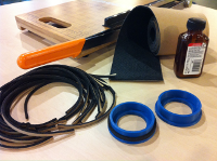
roll. The bungee cord ends were formed into loops using
vinyl electrical tape and terminated with heat-shrink
tubing.
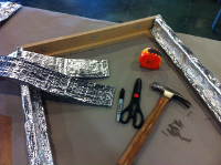
The inner surface of the frame was covered in a layer of
synthetic felt identical to that used on the underside of the
electronics enclosure and secured using brads.
The current frame design is suitable for only one vacuum
table. Either a graduated set of rigid frames or a
segmented frame would be necessary to hold larger sheets in the
event more than one vacuum table were joined together.
Testing:
Incremental empirical tests/inspections were performed during the development of the vacuum former module.These tests included:
- Heating behavior observations of assorted plastics and
plastic thicknesses using a single IR bulb
- Vacuum table seals with covered valve ports under low
internal pressure
- Vacuum table deflection with covered valve ports under low
internal pressure
- Check valve sealing/venting and vacuum table hold down performance tests under low internal pressure: all valves open, all valves closed, and four valves opened / four valves closed
- Arduino sketch and control board output testing using LEDs
- Vacuum forming ABS plastic sheets under varying heating
intervals and bulb standoff distances: with and without
post forming localized heating
Vacuum Forming:
Of a handful of plastics (ABS, polystyrene, lexan, acrylic,
PVC) and plastic thicknesses investigated for vacuum forming
with IR bulb heat sources, black ABS plastic 0.060 inches (1.52
mm) thick was the most responsive and was selected for
additional tests.
MVF operation uses the following steps:
- Mount plastic sheet to underside of frame by pressing frame
against sheet on empty vacuum table surface. Adjust
frame distance from IR bulbs using bolts and bungee cord
- Place die on vacuum table
- Inspect and orient check valves so that they will close under vacuum
- Disable manual override switch
- Adjust potentiometer
- Press "on" switch
- Monitor plastic sheet and adjust elevation of frame in the case of localized overheating
- Power vacuum motor
- Lower and press frame with softened plastic sheet flush against the vacuum table
- Locally heat under-formed areas with a heat gun while still under vacuum
- Shut off vacuum motor and bulbs and remove formed sheet from frame
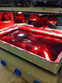
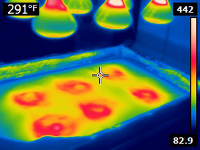
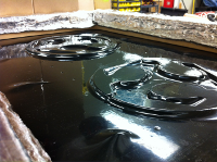
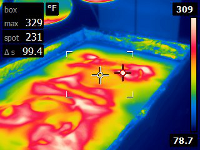
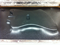
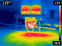
The series of images below show the MVF used to form 0.060 inch (1.52 mm) ABS around objects ranging from 0.335 inches (8.5 mm) to 1.670 inches (42.4 mm) thick. Also pictured are infrared camera images captured during these tests that show the temperature distribution on the plastic's surface. The camera images illustrate the spotted pattern of hot and cold regions which was an expected consequence and a design compromise when using round IR bulbs rather than linear bulbs or linear heating elements. Localized plastic temperatures approached 330F (166C) in some cases.
 |
 |
 |
 |
Increasing the distance between the sheet and the bulbs and heating the sheet for several minutes helped to soften the plastic more evenly.
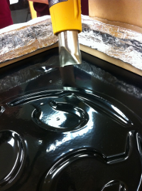
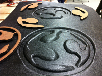
Vacuum formed part definition was improved by locally post-heating areas around sharp corners with a hot air gun while still under vacuum (see Fab Academy logos below). The 42mm thick guitar body shell shown below was not post heated and exhibits a draped appearance with less definition to its lower edge.
The vacuum motor uses its own exhaust to cool itself and is therefore susceptible to overheating if used extensively to pull a vacuum on a covered vacuum table (see IR image below). It was discovered that reversing one of the check valves to bleed air around the vacuum formed plastic sheet, cooled the motor somewhat without significantly affecting the vacuum table's performance. Intermittent vacuum motor use would be recommended.
 |
 |
 |
 |